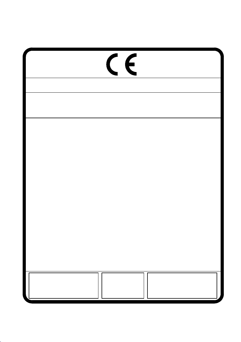
RAIS/attika VISIO L Series User manual

BRUGERMANUAL
BEDIENUNGSANLEITUNG
USER MANUAL
MANUEL D’UTILISATEUR
BRUKERVEILEDNING
BRUKSANVISNING
KÄYTTÖOHJE
GEBRUIKERSHANDLEIDING
VISIO L


RAIS/attika VISIO L
EN 13229:2001+A1:2003+A2:2004 Raumheizer für feste Brennstoffe
Appliance fired by wood
Poêle pour combustibles solides
Produced at:
RAIS A/S, Industrivej 20, 9900 Frederikshavn, Danmark
15a B-VG
EC.NO: 224
AFSTAND TIL BRÆNDBART, BAGVÆG
ABSTAND ZU BRENNBAREN BAUTEILEN, HINTEN
DISTANCE TO COMBUSTIBLE BACK WALL
DIST. ENTRE COMPOSANTS COMBUSTIBLES, ARRIÈRE
AFSTAND TIL BRÆNDBART, SIDEVÆG
ABSTAND ZU BRENNBAREN BAUTEILEN, SEITE
DISTANCE TO COMBUSTIBLE SIDE WALL
DISTANCE ENTRE COMPOSANTS COMBUSTIBLES, COTÉ
AFSTAND TIL BRÆNDBART, MØBLERING
ABSTAND VORNE ZU BRENNBAREN MÖBELN
DISTANCE TO FURNITURE AT THE FRONT
DISTANCE ENTRE COMPOSANTS COMBUSTIBLES, DEVANT
CO EMISSION (REL. 13% O2)
CO EMISSION IN DEN VERBRENNUNGSPRODUKTEN (BEI 13%O2)
EMISSION OF CO IN COMBUSTION PRODUCTS (AT 13%O2)
EMISSION CO DANS LES PRODUITS COMBUSTIBLES (À 13%O2)
NOMINEL EFFEKT / HEIZLEISTUNG /
THERMAL OUTPUT / PUISSANCE CALORIFIQUE:
RØGGASTEMPERATUR / ABGASTEMPERATUR /
FLUE GAS TEMPERATURE / TEMPÉRATURE DES GAZ DE FUMÉE:
VIRKNINGSGRAD / ENERGIEEFFIZIENZ /
ENERGY EFFIENCY /EFFICACITÉ ÉNERGÉTIQUE:
DK: Brug kun anbefalede brændsler. Følg instrukserne i
brugermanualen. Anordningen er egnet til røggassamleledning og intervalfyring.
DE: Lesen und befolgen Sie die Bedienungsanleitung.
Zeitbrandfeuerstätte. Nur empfohlene Brennstoffe einsetzen.
UK: Fuel types (only recommended). Follow the installation and
operating instruction manual. Intermittent operation.
F: Veuillez lire et observer les instructions du mode d'emploi.
Foyer à durèe de combustion limitèe, homologué pour cheminée à
connexions multiples. Utiliser seulement les combustibles recommandés.
Hergestellt für /Produced for:
ATTIKA FEUER AG, Brunnmatt 16, CH-6330 Cham / RAIS A/S, Industrivej 20, DK-9900 Frederikshavn
STØV / STAUB /
DUST / POUSSIÈRES: DK: 28 mg/Nm3 / DE: 28 mg/Nm3
UK: 28 mg/Nm3 / FR: 28 mg/Nm3
DK: 225°C / DE: 225°C
UK: 225°C / FR: 225°C
DK: 10,3 kW / DE: 10,3 kW
UK: 10,3 kW / FR: 10,3 kW
DK: 81% / DE: 81%
UK: 81% / FR: 81%
DK: BRÆNDE
DE: HOLZ
UK: WOOD
FR: BOIS
DK: SE BRUGERVEJLEDNING
DE: SIEHE BEDIENUNGSANLEITUNG
UK: SEE USER MANUAL
FR: CONSULTEZ LE GUIDE DE L'UTILISATEUR
DK: SE BRUGERVEJLEDNING
DE: SIEHE BEDIENUNGSANLEITUNG
UK: SEE USER MANUAL
FR: CONSULTEZ LE GUIDE DE L'UTILISATEUR
DK: 1100 mm/SE BRUGERVEJLEDNING
DE: 1100 mm/SIEHE BEDIENUNGSANLEITUNG
UK: 1100 mm/SEE USER MANUAL
FR: 1100 mm/CONSULTEZ LE GUIDE DE L'UTILISATEUR
DK: 0,098%
DE: 0,098% / 1226 mg/Nm3
UK: 0,098%
FR: 0,098%
CE Label:
Visio 2 L Left / Visio 2 L Right
Visio 3 L
19
Visio 2 L Left / Visio 2 L Right
Visio 3 L
Notified Body: 1235
Mærkeplade/CE Zeichen/Manufacturer’s plate/Plaque signalétique/Merkeplate/Märkplät

3
34
5 6
7 8
21
Indstilling af spjæld / Einstellung der Luftklappe / Adjustment of the air damper /
Réglage du volet d’air / Innstilling av spjeldet / Inställning av spjället
Position 1 - Posisjion 1
CC
D
E
F
VISIO
3 positioner af spjældhåndtag
Position 2 - Posisjion 2
CC
D
E
F
VISIO
3 positioner af spjældhåndtag
Position 3 - Posisjion 3
CC
D
E
F
VISIO
3 positioner af spjældhåndtag
Optænding og påfyldning / Anzünden und Nachlegen / Lighting and fuelling /
Allumage et remplissage / Opptenning og påfylling / Upptänding och påfyllning
3

We cannot be held responsible for any misprints.
RECYCLING:
The oven is wrapped in packaging that is recyclable. This
must be disposed of according to national rules regard-
ing the disposal of waste.
The glass can not be reused.
The glass should be discarded along with the residual
waste from ceramics and porcelain.
Pyrex glass has a higher melting temperature and there-
fore can not be reused.
If discarded you make an important positive contribution
to the environment.
FIRE ENVIRONMENTALLY FRIENDLY!
5 Eco-friendly advices for sensible heating
- common sense both environmentally and economically.
1. Effective lighting. Use small pieces of wood (fir tree) and a suit-
able fire lighter, for example paraffined wood wool/sawdust.
Open the air damper, so plenty of air is fed to the stove and
the gases from the heated wood can burn rapidly.
2. Light the fire with only little wood at a time - this gives the best
combustion. Remember plenty of air for every time new wood
is added.
3. When the flames are diminished, adjust the air damper so that
the air supply is reduced.
4. When only glowing embers remain, air flow can be reduced
further, so heating demand is just covered. With a lower air
supply the charcoal will burn slower and the heat loss through
the chimney is reduced.
5. Use only dry wood - ie. wood with a humidity of 15 to 20%.
GB

5
VISIO L
-
10-09-2019
5
Revision :
Date :
INTRODUCTION ............................................................................................................ 6
WARRANTY .................................................................................................................. 7
SPECIFICATIONS............................................................................................................ 8
DISTANCES/DIMENSIONS .............................................................................................. 9
CONVECTION ............................................................................................................. 11
CHIMNEY ................................................................................................................... 12
CHOICE OF MATERIAL FOR INSTALLATION .................................................................. 13
INSTALLATION............................................................................................................. 13
FITTING THE REFLECTIVE INSULATION PANEL............................................................... 14
TRANSPORT SAFETY FITTING....................................................................................... 15
INSTALLATION OF FIREPLACE INSERT VISIO L 2............................................................ 16
INSTALLATION DISTANCES VISIO L 2............................................................................ 18
INSTALLATION OF FIREPLACE INSERT VISIO L 3............................................................ 19
INSTALLATION DISTANCES VISIO L 3............................................................................ 21
CONVECTION AIR....................................................................................................... 22
AIR-SYSTEM................................................................................................................ 24
FUEL ........................................................................................................................... 25
DRYING AND STORING............................................................................................... 26
REGULATION OF THE SUPPLY AIR TEMPERATURE ........................................................ 26
VENTILATION .............................................................................................................. 26
USING A WOOD-BURNING STOVE .............................................................................. 27
LIGHTING FOR THE FIRST TIME.................................................................................... 27
LIGHTING AND STOKING ............................................................................................ 28
INSPECTION................................................................................................................ 28
WARNING................................................................................................................... 29
CLEANING AND CARE ................................................................................................ 30
MAINTENANCE/SPARE PARTS...................................................................................... 30
CLEANING THE DOOR GLASS ..................................................................................... 31
CLEANING THE COMBUSTION CHAMBER................................................................... 32
CLEANING THE FLUE................................................................................................... 33
OPERATING INTERUPTIONS ......................................................................................... 34
CONVERTING TO SELF-LOCKING DOOR ...................................................................... 36
TEST CERTIFICATE ....................................................................................................... 38
GB

6
Introduction
Thank you for purchasing a RAIS/
attika
wood burning stove.
A RAIS/
attika
wood burning stove is more than just a heat source. It also shows that
you care about design and quality in your home.
To make the most of your wood burning stove it is important that you read the manual
thoroughly, before installing and using it.
In the case of warranty coverage, and for general queries regarding your wood burn-
ing stove, it is important that you know the stove’s production number. We therefore
recommend that you write down the number in the table below.
The production number is located in the bottom left corner of the wood-burning stove.
Date: Distributor:
GB

77
WARRANTY
RAIS/
attika
– wood-burning stoves are tested repeatedly in terms of safety, as well as
material and manufacturing quality. We grant warranty on all models, starting with the
date of installation.
The warranty refers to:
• documented malfunctions due to faulty manufacture
• documented material defects
The warranty does not cover:
• door and glass seals
• ceramic glass
• chamber lining
• appearance of the surface structure or natural stone texture
• appearance or changes of colour of the stainless steel or patina surfaces
• expansion noise
The warranty is invalidated in case of:
• damages, caused by overfiring
• damages, caused by external influence and the use of unsuitable fuels
• non-observance of statutory or recommended installation guidelines, and modifi-
catons to the wood-burning stove
• non-observance of service and care provisions
Please contact your retailer in the event of damage. We determine the way to repair
the damage, in case of warranty claims. In the event of repair, we ensure proper and
professional execution.
Warranty claims submitted for additionally delivered or repaired parts are subject to
national/EU laws and regulations in terms of renewed warranty periods.
Please contact RAIS A/S for the applicable warranty provisions.
GB

8
DTI
Danish Technological Institute
Teknologiparken Kongsvang Allé 29, DK-8000 Aarhus C
Danmark
www.dti.dk
Telefon: +45 72 20 20 00
Fax: +45 72 20 10 19
8
DTI ref.: 300-ELAB-2383-EN
VISIO L 2 VISIO L 3
Nominal output (kW): 10.3
Min./Max. output (kW): 8 - 12
Heating area (m2): 200
Stove’s width/depth/height (mm): 1141 x 610 X 1765 1089 X 634 X 1765
Combustion chamber’s width/depth/
height (mm): 708 X 256 X 541 660 X 256 X 545
Recommended amount of wood
when fuelling (kg).
Distributed on 2-4 logs of wood of
approx. 30 cm
2.9
Min. uptake / Min. draught (Pascal): -11
Weight (kg): approx 293
Efficiency (%): 81
CO-emission at 13% O2(%): 0.098
(1226mg/Nm³)
NOx-emission at 13% O2(mg/Nm³): 73
Particles emission acc. to
NS3058/3059 (g/kg): 1.0
Dust measured acc. to Din+ (mg/
Nm³): 26
Smoke gas mass flow (g/s): 11.3
Smoke gas temperature (°C): 225°
Smoke gas temperature (°C) at flue
collar: 270°
Intermittent operation: Refuelling should be
undertaken within 58 minutes.
Specifications
VISIO L are inset stoves with a vertically operated door.
GB

9
A-A
B-B
A
A
B
B
59
n198
116
620
521 539
494,1
413
494
482 0
367
932,5
1596
59
482
607
1765
102
1638
198
621
541
15
n149
A-A
B-B
A
A
B
B
59
n
198
116
620
521 539
494,1
413
494
482 0
367
932,5
1596
59
482
607
1765
102
1638
198
621
541
15
n149
A-A
B-B
A
A
B
B
59
n
198
116
620
521 539
494,1
413
494
482 0
367
932,5
1596
59
482
607
1765
102
1638
198
621
541
15
n149
A-A
B-B
A
A
B
B
59
n198
116
620
521 539
494,1
413
494
482 0
367
932,5
1596
59
482
607
1765
102
1638
198
621
541
15
n149
9
Dimensional drawings
NB: The flue spigot at the top outlet can be turned freely. (Radius 102 mm).
VISIO L 2
With top outlet
With rear outlet
GB

10
A-A
B-B
A
A
B
B
544,3 544,3
n
198
1088,6
169 465504
1638
26 608
538
473 473
634
0
368
931
1581
411153 481
1765
5457
102
n149
A-A
B-B
A
A
B
B
544,3 544,3
n
198
1088,6
169 465504
1638
26 608
538
473 473
634
0
368
931
1581
411153 481
1765
5457
102
n149
A-A
B-B
A
A
B
B
544,3 544,3
n
198
1088,6
169 465504
1638
26 608
538
473 473
634
0
368
931
1581
411153 481
1765
5457
102
n149
10
VISIO L 3
With top outlet
With rear outlet
GB

1111
Convection
RAIS/
attika
stoves are convection stoves. Convection means that there is a circula-
tion of air, which ensures that the heat is distributed more evenly throughout the entire
room. The cold air is sucked in at the base of the stove up through the convection
channel, which runs along the stove’s combustion chamber.
The heated air pours out at the top of the stove, which ensures a circulation of warm
air throughout the room.
Note, however, that all exterior surfaces become hot during use - so take extreme care.
Use the insert optimally.
By installing hot air nozzles and flexible hoses (or similar) on top of the stove, it is pos-
sible to ”move” the heat to other rooms.
Consider the placement of convection and outlet holes. Ensure that the area require-
ments are respected and that the holes are not blocked from the outside. There may
be discoloration of the wall above the stove doors, and above the convection outlet
holes. This is due to the ascending hot air.
RAIS/
attika
accepts no liability for installation or consequential damages.
GB

1212
Chimney
The chimney is the driving force which makes the stove function. In order for the stove
to perform satisfactorily the chimney height must be sufficient to ensure the correct
draught of 14 to 18 Pa so as to clear the products of combustion and prevent problems
of smoke emanating into the room when firing.
NOTE: A chimney height of not less than 4.5 metres measured vertically from the outlet
of the stove to the top of the chimney should be satisfactory. Alternatively the calcula-
tion procedure given in BS 5854:1980 may be used as the basis for deciding whether a
particular chimney design will provide sufficient draught.
The outlet from the chimney should be above the roof of the building in accordance
with the provisions of Building Regulations Approved Document J.
If installation is into an existing chimney then it must be sound and have no cracks or
other faults which might allow fumes into the house. Older properties, especially, may
have chimney faults or the cross section may be too large i.e. more than 230 mm x 230
mm. Remedial action should be taken, if required, seeking expert advice, if necessary. If
it is found necessary to line the chimney then a flue liner suitable for solid fuel must be
used in accordance with Building Regulations Approved Document J.
Any existing chimney must be clear of obstruction and have been swept clean immedi-
ately before installation of the stove. If the stove is fitted in place of an open fire then
the chimney should be swept one month after installation to clear any soot falls which
may have occurred due to the difference in combustion between the stove and the
open fire.
If there is no existing chimney then either a prefabricated block chimney in accordance
with Building Regulations Approved Document J or a twin walled insulated stainless
steel flue to BS 1856-1 can be used. These chimneys must be fitted in accordance with
the manufacturer’s instructions and Building Regulations.
A single wall metal fluepipe is suitable for connecting the stove to the chimney but is
not suitable for using for the complete chimney. The chimney and connecting fluepipe
must have a minimum diameter of 180 mm. Any bend in the chimney or connecting
fluepipe should not exceed 45°. 90°bends should not be used.
Combustible material should not be located where the heat dissipating through the
walls of fireplaces or flues could ignite it. Therefore when installing the stove in the
presence of combustible materials due account must be taken of the guidance on the
separation of combustible material given in Building Regulations Approved Document J
and also in these stove instructions.
If it is found that there is excessive draught in the chimney then either an adjustable
flue damper or alternatively a draught stabiliser should be fitted. The adjustable flue
damper should not close off the flue entirely but should in its closed position leave a
minimum continuous opening free area of at least 20 % of the total cross sectional
area of the flue or fluepipe.
GB

1313
Installation
Adequate provision e.g. easily accessible soot door or doors must be provided for
sweeping the chimney and connecting fluepipe.
You should also familiarise yourself with the draught conditions for chimneys with 2
flues.
The stove is supplied with a ø200 mm flue outlet spigot.
The stove is approved with a ø180 mm flue outlet spigot, which can be retrofitted.
The flue spigot can be changed from top outlet to back
outlet. The clamp on the outlet is loosened and
adjusted as desired.
NOTE!
if the stove is installed with a back outlet, the back wall
must be non combustible ( e.g.a brick wall).
For strong draughts, the chimney or flue should be fitted
with a draught stabiliser. In which case, it is important to
ensure that there is a free flow-through area of minimum
20 cm² when the regulating gate is shut. Otherwise, the
fuel energy may not be used optimally. If, at any time, you
are unsure about the condition of the chimney, you should contact a chimney sweep.
Remember that access to the access door should be kept clear.
Make sure to establish access to cleaning the stove, flue collar and pipe.
Material selection
Choose non-combustible materials for panels/bricks with a thermal resistance greater
than 0.03 m2xK/W. Thermal resistance is defined as the thickness (in m) divided by the
wall’s lambda value. Consult with your installer/chimney sweep.
During testing, the wood-burning stove is installed in a cabinet made from non-flam-
mable 50 mm calcium silicate panels (Skamotec 225).
GB

1414
Mounting the reflektor plate - VISIO L 2
The stove is fitted with a reflector
plate on the back side.
Dismount the reflector plate and
turn it upside down. Mount the
plate reusing the screws (as shown).
Mounting the reflector plate - VISIO L 3
The stove is fitted with a
reflector plate.
Dismount the reflector plate and turn it
upside down. Mount the plate by reus-
ing the screws at the bottom.
GB

1515
Bend the cut-outs and mount
the plate to the top of the
stove.
Transport safety
Before installing the stove remove the transport safety:
• on VISIO 1 remove 2 screws on the side.
• on VISIO 2 remove 1 screw on the side.
• on VISIO 3 remove 2 screws on the back side.
GB

1616
VISIO 2 L
Applies to installation in non-flammable panels or in brick.
If other materials are used, they must have better or the same characteristics as 50 mm
Skamotec 225.
To achieve the necessary distances from the wood-burning stove to the panel/brick-
work, the internal dimensions of the cassette must be 665 x 1195 x 1950 mm. If this is
complied with, the exterior rear side of the cassette may lie against a flammable wall.
There must be a top plate in the cabinet just above the convection ejection.
A fireplace insert may never be installed in a cavity that is too tight, since steel expands
when heated.
GB

1717
Hole dimensions (height x width x depth) min. 570.5 x 999.3 x 549.5 mm (interior
dimensions).
Hole dimension for wood-burning stove with installation frame. A height
of 568 mm provides an air gap of 5 mm above the top frame. This air gap is necessary
because the wood-burning stove will expand when heating up.If this air gap is not cre-
ated, it can result in damage to the brickwork!
GB

1818
GB

19
Established:
Designer: Project manager:
Format:
Approved:
Drawing no.:Revision:Project:
Drawing name:
INDUSTRIVEJ 20, 9900 FREDERIKSHAVN, DENMARK
Phone +45 98 47 90 33 - Fax +45 98 47 92 91
E-mail: info@rais.dk - Homepage: www.rais.dk
Corrections:
D M Y
ksj
09-01-2019 A3 Indbygningsmål side
16
19
VISIO 3 L
Applies to installation in non-flammable panels or in brick.
If other materials are used, they must have better or the same characteristics as 50 mm
Skamotec 225.
To achieve the necessary distances from the wood-burning stove to the panel/brick-
work, the internal dimensions of the cassette must be 700 x 988 x 1950 mm. If this is
complied with, the exterior rear side of the cassette may lie against a flammable wall.
There must be a top plate in the cabinet just above the convection ejection.
A fireplace insert may never be installed in a cavity that is too tight, since steel expands
when heated.
GB
This manual suits for next models
2
Table of contents
Other RAIS/attika Stove manuals
Popular Stove manuals by other brands

Porter&Charles
Porter&Charles IR76S manual

Garde
Garde Sedgley Assembly and user instructions

Haas+Sohn
Haas+Sohn VIKING 75 Installation and maintenance instructions

Alfa Plam
Alfa Plam Elita Instructions for installation and use

Quality Craft
Quality Craft SOQC935-MBK instruction manual

Alfa Plam
Alfa Plam FUTURO L Instructions for installation and use