Raisonance REva User manual

REva
Raisonance Universal Evaluation Board
with RLink for Microcontrollers
User Guide
REva Mother board
(versions v1.x, v2.x and RF)
Hardware Description
and User's Guide
September 2007

REva User Guide: Mother Board
Information in this document is subject to change without notice and does not represent a commitment
on the part of the manufacturer. The software described in this document is furnished under license
agreement or nondisclosure agreement and may be used or copied in accordance with the terms of the
agreement. It is against the law to copy the software on any medium except as specifically allowed in
the license or nondisclosure agreement. No part of this manual may be reproduced or transmitted in any
form or by any means, electronic or mechanical, including photocopying, recording, or information
storage and retrieval systems, for any purpose other than the purchaser’s personal use, without prior
written permission.
Every effort was made to ensure the accuracy in this manual and to give appropriate credit to persons,
companies and trademarks referenced herein.
©Copyright 2007 RAISONANCE SAS. All rights reserved
Raisonance is a registered trademark of RAISONANCE S.A.S.

REva User Guide: Mother Board
Table of Contents
1. PRESENTATION 5
1.1 Description of the delivered package 7
1.2 REva-RLink connection 10
2. OPERATING MODES 12
2.1 Attached Mode: USB Powered, on-board ISP/ISD 13
2.2 Broken Apart Mode: Auxiliary power supply, cable ISP/ISD 14
3. REVA MOTHER BOARD 16
3.1 Layout of the REva mother board 17
3.2 Power supply area (REva v1.x) 18
3.3 Power supply area (REva v2.x) 20
3.4 ISP/ISD connection area 22
3.5 Reset area 23
3.6 Digital outputs area 23
3.7 Digital inputs area 24
3.8 Analog area 25
3.9 Communication area 26
3.10 Secondary serial / CAN area 28
3.11 Wrapping zone (REva standard up to v2.10) 28
3.12 RF connector (REva RF 'ZigBee' only) 28
4. EMBEDDED RLINK 30
4.1 Configuration and Functionalities 30
- 3 - Raisonance

REva User Guide: Mother Board
4.2 Limitations 31
5. DAUGHTER BOARDS 32
5.1 Insertion/Extraction 33
5.2 Caution 33
5.3 Dedicated documentations 34
6. MOTHER BOARD SCHEMATICS 36
6.1 REva v1.0 37
6.2 REva v2.0 39
6.3 REva v2.10 41
6.4 REva v2.1Z 'ZigBee' 43
7. VERSION HISTORY 45
8. APPENDIX 46
8.1 Compliance 46
Raisonance - 4 -

REva User Guide: Mother Board 1. Presentation
1. Presentation
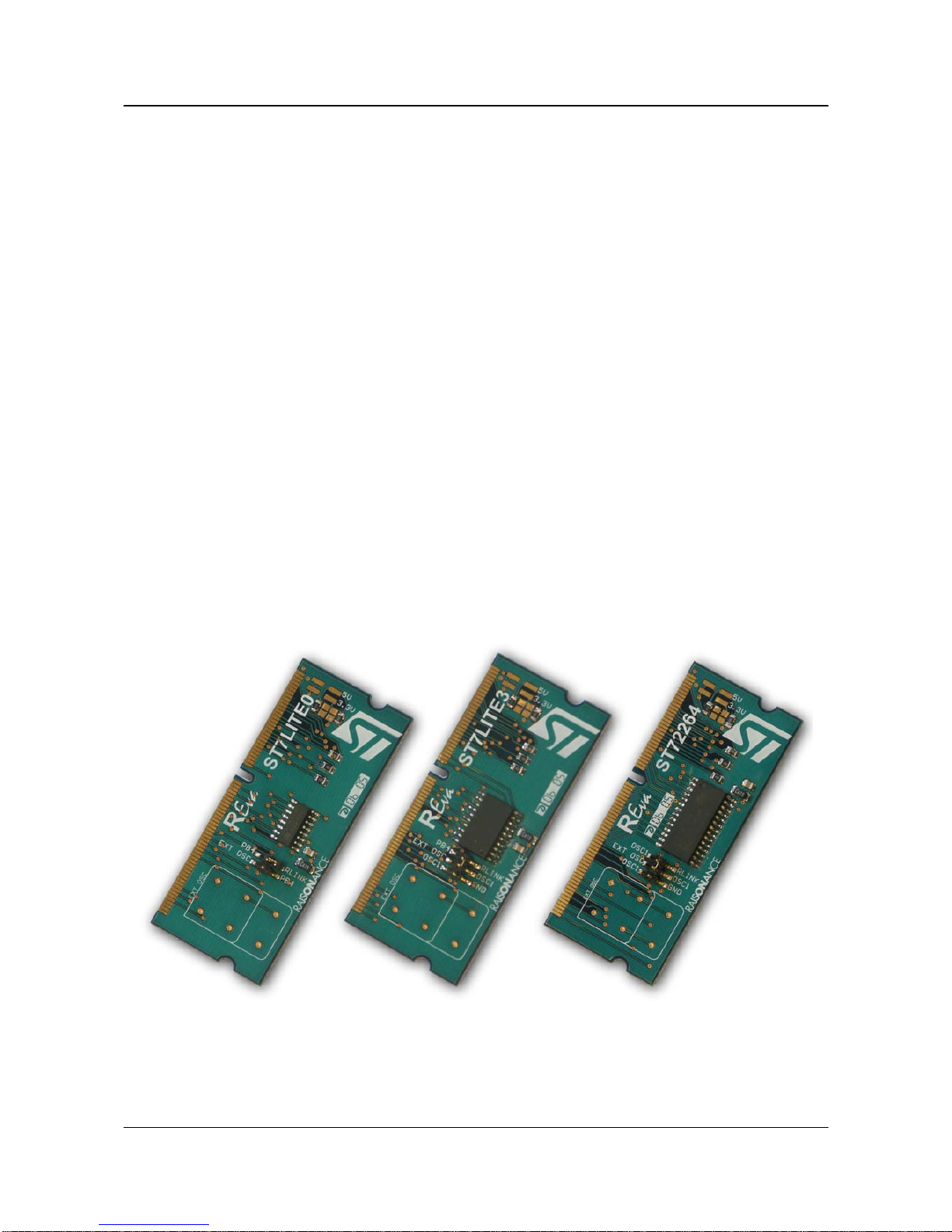
The REva is a universal evaluation board that has been designed for quick
and easy evaluation of a wide range of microcontrollers. It is made up of a
generic REva mother board with embedded RLink in-circuit programmer and
debugger, and a daughter board featuring a target microcontroller.
IMPORTANT NOTE:
This manual describes different versions of the REva boards. The major part
of this User Guide refers is common to all the existing REva boards. For the
parts where the boards differ, a notice (in blue) will indicate it.
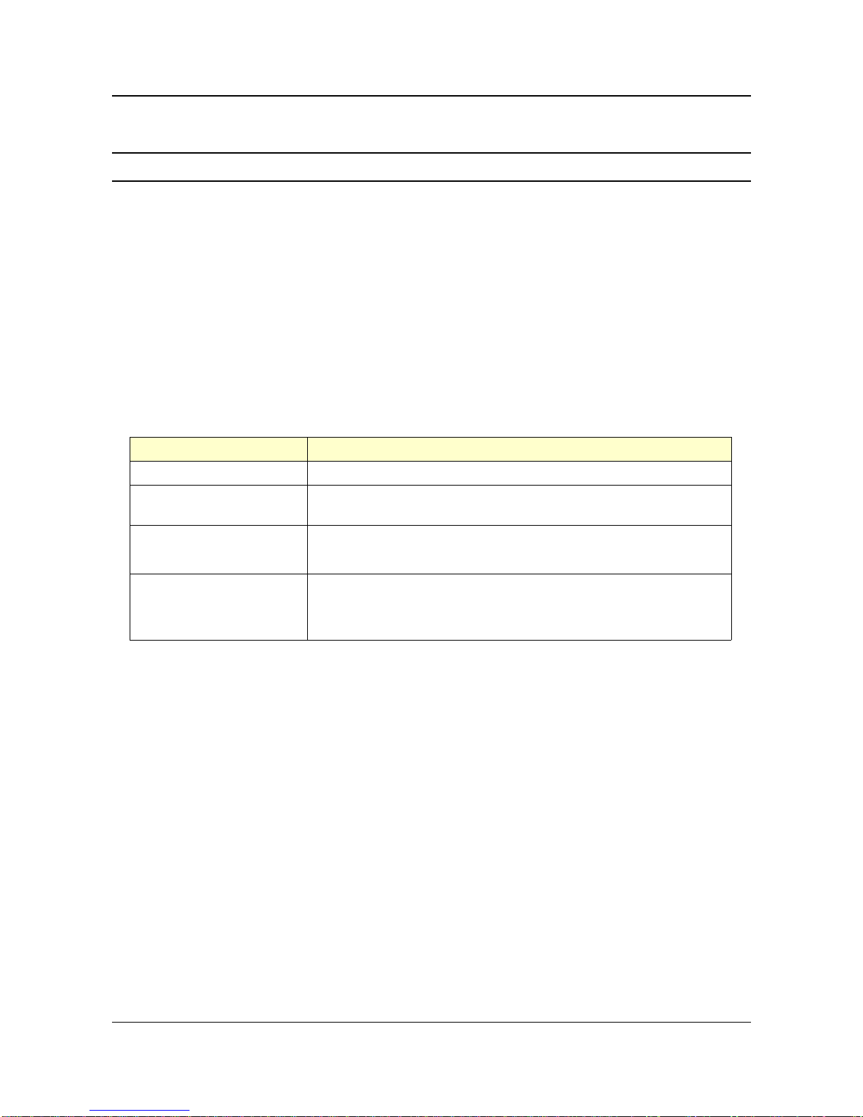
Version Short description
REva v1 First version of the REva board.
REva v2 Very similar to V1.0, but the voltage of the regulator is now fixed by the
daughter board itself (instead of a set of jumpers on the REva board).
REva RF 'ZigBee' The REva RF 'ZigBee' is designed for RF applications and features an
extension connector to plug a RF external module.
REva v3 The RLink is not breakable anymore. New peripherals are also added: LCD
monitor, MEMS accelerometer, ...
A DIFFERENT MANUAL DESCRIBES THE REva v3 (AND LATER).
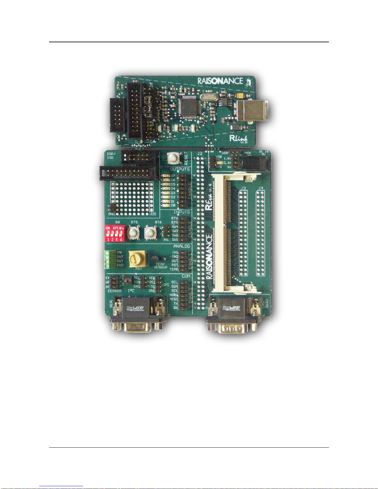
The REva's key features include:
●Digital and analog I/O evaluation features including on-board LEDs,
buttons, switches, external analog connector, temperature sensor
and potentiometer,
●On-board I²C EEPROM and bus extension connector,
●On-board RS232 driver and DB9 connector,
●SPI, CAN and USB connections (depending on the target device),
●Embedded RLink for in-circuit debugging and in-circuit programming,
●VDD settings for 1.8V, 3.3V and 5V microcontrollers,
●USB powered, no external power required.
This chapter gives an overview of the REva package and the physical
characteristics of the mother board.
- 5 - Raisonance

1. Presentation REva User Guide: Mother Board
Raisonance - 6 -

REva User Guide: Mother Board 1. Presentation
1.1 Description of the delivered package
The REva package includes:
●1 REva mother board (see Illustration 2),
●1 RLink attached to the mother board (see Illustration 2),
●REva daughter board(s), depending on the purchased kit,
●all required cables,
●1 RAISONANCE software CD,
●1 QuickStart tutorial,
●some target microcontroller specific documentation.
The REva mother board can be powered by an external power supply which is not provided.
The characteristics of the power supply are:
●9V DC output,
●2.1 x 5 mm jack connector with ground signal on the outside.
- 7 - Raisonance
Illustration 1: Sample daughter boards

1. Presentation REva User Guide: Mother Board
At the time of manufacturing, the REva and the RLink are connected to allow in-circuit debugging and
in-circuit programming of the microcontroller on the REva daughter board without additional power
supply or cables.
The two tools can also be easily broken apart so that both the REva and the RLink can be used
independently, or together. This requires the use of the furnished cable and an additional power supply
(not furnished) for the REva.
Raisonance - 8 -
Illustration 2: Overview of the REva mother board with RLink

REva User Guide: Mother Board 1. Presentation
Note: When separated from the REva, the RLink has the same in-circuit debugging and programming
characteristics as the stand-alone RLink version 2.0.
As a result there are two possible configurations for using the REva:
●“Attached Mode”: REva and RLink boards are attached, no connection cable is required and
power is supplied by the USB connection (see paragraph 2.1).
●“Broken apart mode”: The REva is connected to the RLink (or other tool that supports in-
circuit debugging and programming) via a connection cable. Power is supplied by a 9V
auxiliary power supply (see Illustration 3 and paragraph 2.2).
Illustration 3: Overview of the broken REva Board
- 9 - Raisonance

1. Presentation REva User Guide: Mother Board
1.2 REva-RLink connection
The REva and the RLink are connected by eight points at the time of manufacturing. Through these
points, 16 signals are passed including those for:
●in-circuit debugging
●in-circuit programming
●USB power supply
●the grounds of the two boards
!!! Warning !!!
After the boards are broken apart, you must use the provided cable to connect the boards and
an external 9V power supply. Only break the boards apart if it is required for your application.
To break apart the two boards, place the separation along the edge of a desk. Then, press down on the
RLink with one hand while maintaining the mother board with the other hand.
Raisonance - 10 -
Illustration 4: REva-RLink connection
Illustration 5: Separation procedure.

REva User Guide: Mother Board 1. Presentation
- 11 - Raisonance

2. Operating modes REva User Guide: Mother Board
2. Operating modes
The following chapter provides a detailed description of each of the REva's
major operating configurations/modes:
●Attached Mode: boards connected and powered from USB
●Broken Apart Mode: boards separated and powered by a 9V auxiliary
power supply
Raisonance - 12 -

REva User Guide: Mother Board 2. Operating modes
2.1 Attached Mode: USB Powered, on-board ISP/ISD
In this mode, 1.8V daughter boards are not supported.
The RLink must not be used to program external target microcontrollers when a daughter board
is inserted.
- 13 - Raisonance

2. Operating modes REva User Guide: Mother Board
2.2 Broken Apart Mode: Auxiliary power supply, cable ISP/ISD
There are no restrictions for this mode.
This is the only mode that allows the debugging and programming of 1.8V target microcontrollers.
Raisonance - 14 -

REva User Guide: Mother Board 2. Operating modes
- 15 - Raisonance

3. REva mother board REva User Guide: Mother Board
3. REva mother board
This chapter describes the REva's evaluation features and their limitations.
Features are grouped in the following thematic areas:
3. REva mother board................................................................................................................................15
3.1 Layout of the REva mother board............................................................16
3.2 Power supply area (REva v1.x)................................................................17
3.3 Power supply area (REva v2.x)................................................................19
3.4 ISP/ISD connection area..........................................................................21
3.5 Reset area...............................................................................................22
3.6 Digital outputs area..................................................................................22
3.7 Digital inputs area....................................................................................23
3.8 Analog area..............................................................................................24
3.9 Communication area................................................................................25
3.10 Secondary serial / CAN area..................................................................27
3.11 Wrapping zone (REva standard up to v2.10).........................................27
3.12 RF connector (REva RF 'ZigBee' only)..................................................27
Raisonance - 16 -

REva User Guide: Mother Board 3. REva mother board
3.1 Layout of the REva mother board
Illustration 6 shows the thematic areas for the REva's evaluation features.
The REva mother board exists in two versions. The version number (1.0 or 2.0) is printed on the
mother board next to the SO-DIMM connector.
The only difference between the two versions is in the jumpers in the power supply area. The following
sections describe the use of the power supply area for each version.
- 17 - Raisonance
Illustration 6: REva mother board features

3. REva mother board REva User Guide: Mother Board
3.2 Power supply area (REva v1.x)
This area allows you to choose the voltage to be used on the whole REva board as well as on the
daughter board. Because of the dropout voltage of the regulator, the 5V voltage cannot be generated
from the USB 5V. Thus, to use 5V target microcontrollers without external power supply, the USB
power supply must not pass through the regulator but must be used directly.
3.2.1 View
3.2.2 Possible configurations
Raisonance - 18 -

REva User Guide: Mother Board 3. REva mother board
3.2.3 Features
●1 jack for the connection of auxiliary 9V power supply to power the REva board in broken apart
mode. Should you require one, the 9V power supply should output 9V DC and have a 2.1x5mm
jack with the ground signal on the outside.
●1 two-position jumper for configuring the regulator input. When the jumper is in the “Jack”
position, the regulator input is the external 9V power supply. When it is in the “USB” position, the
regulator input is the USB power supply of the embedded RLink.
●1 three-position jumper to configure the regulator. This defines the voltage delivered by the
regulator. When no jumper is set, the voltage is 1.8V.
●1 two position jumper to select the VDD source. It can be either the 5V of the embedded USB or the
output of the regulator (which must then be properly configured).
●1 green LED which is lit when the REva board is powered.
3.2.4 Limitations
The USB 5V is actually 4.8V because a low drop out diode is connected between the USB connector
and the board, to protect the PC. For accurate 5V power supply, use an external power supply.
Once the RLink has been separated from the REva mother board, the USB power supply is no
longer connected to the power supply area. The use of an external 9V DC power supply is mandatory,
the “Regulator Input” jumper must remain in the “Jack” position and the “VDD selection” jumper must
remain in the “REG” position.
With 1.8V power supply, the LEDs on the board are dim and some features are not available (serial
communication, I²C EEPROM and temperature measurement).
- 19 - Raisonance

3. REva mother board REva User Guide: Mother Board
3.3 Power supply area (REva v2.x)
This area allows to choose the voltage to be used on the whole REva board as well as on the daughter
board. On the REva v2.0 the daughter board configures automatically the regulator and defines the
possible sources for VDD. Direct USB 5V must not be used with 3.3V daughter boards. It could
damage them.
3.3.1 View
3.3.2 Possible configurations
Raisonance - 20 -
Other manuals for REva
1
Table of contents
Other Raisonance Motherboard manuals