Raisonance REva User manual

REva
Raisonance Universal Evaluation Board
Motherboard (version 3 onwards)
User Guide
Document version
23 June 2009

REva User Guide v3
Contents
1. INTRODUCTION................................................................................................................4
1.1 Purpose of this manua ...................................................................................................................4
1.2 Scope of this manua .......................................................................................................................4
1.3 Additiona he p or information..........................................................................................................4
2. REVA V3 OVERVIEW........................................................................................................5
2.1 Key features....................................................................................................................................5
2.2 Version history summary.................................................................................................................5
2.3 De ivered package...........................................................................................................................5
3. REVA MOTHERBOARD....................................................................................................7
3.1 Power supp y...................................................................................................................................7
3.1.1 Externa power supp y..............................................................................................................7
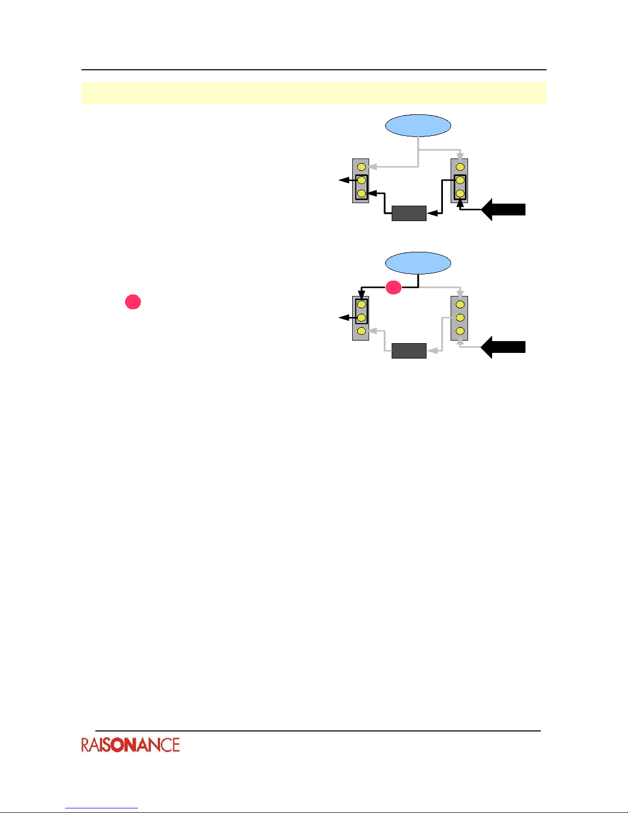
3.1.2 Possib e power supp y configurations......................................................................................7
3.1.3 Features...................................................................................................................................8
3.1.4 Limitations................................................................................................................................8
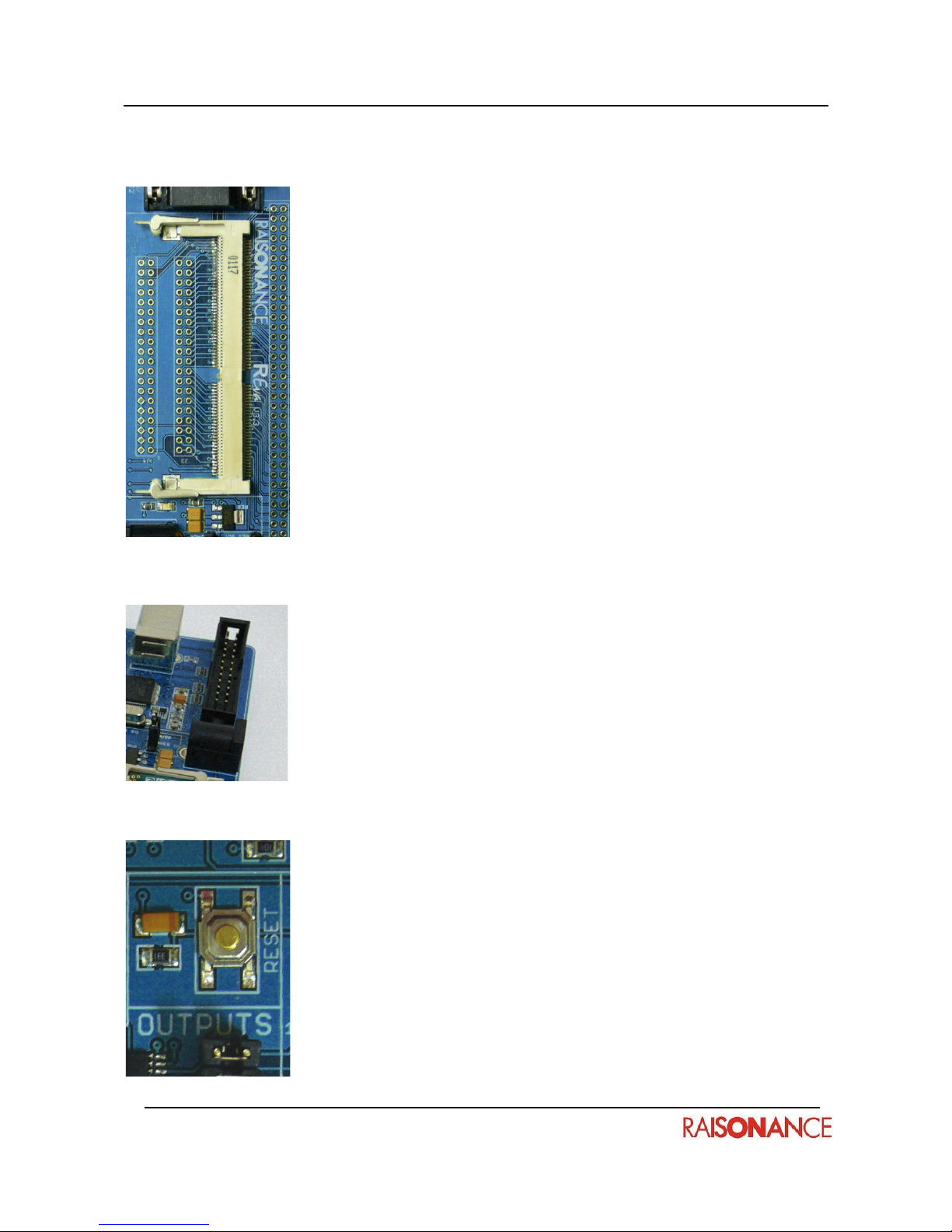
3.2 Daughter board connection.............................................................................................................9
3.2.1 Features...................................................................................................................................9
3.2.2 Limitations................................................................................................................................9
3.3 ISP/ISD connection area.................................................................................................................9
3.4 Reset area.......................................................................................................................................9
3.4.1 Features...................................................................................................................................9
3.4.2 Limitations................................................................................................................................9
3.5 Digita outputs area.......................................................................................................................10
3.5.1 Features.................................................................................................................................10
3.6 Digita inputs area.........................................................................................................................11
3.6.1 Features.................................................................................................................................11
3.6.2 Limitations..............................................................................................................................11
3.7 Ana og area...................................................................................................................................12
3.7.1 Features.................................................................................................................................12
3.7.2 Limitations..............................................................................................................................12
3.8 Communication area.....................................................................................................................13
- 2 -

REva User Guide v3
3.8.1 Features.................................................................................................................................13
3.8.2 Limitations..............................................................................................................................13
3.9 Secondary seria / CAN area.........................................................................................................14
3.10 Wrapping zone............................................................................................................................14
4. EMBEDDED RLINK..........................................................................................................15
4.1 Configuration and functiona ities...................................................................................................15
4.1.1 ICC.........................................................................................................................................15
4.1.2 A other protoco s (JTAG, SWIM and others)........................................................................16
5. DAUGHTER BOARDS.....................................................................................................17
5.1 Insertion and extraction.................................................................................................................17
5.1.1 Insertion.................................................................................................................................17
5.1.2 Extraction...............................................................................................................................17
5.1.3 Insertion/extraction cyc es......................................................................................................17
5.1.4 Power supp y cautions...........................................................................................................17
5.2 Dedicated documentation.............................................................................................................18
6. MOTHERBOARD SCHEMATICS....................................................................................19
7. CONFORMITY.................................................................................................................21
8. GLOSSARY......................................................................................................................22
- 3 -

1. ntroduction REva User Guide v3
1. ntroduction
The REva is a universa eva uation board that has been designed for quick and easy eva uation of a
wide range of microcontro ers. It is made up of a generic REva motherboard with embedded RLink in-
circuit programmer and debugger, and a daughter board featuring a target microcontro er.
MPORTANT NOTE:
This manua describes version 3 of the REva boards (and ater).
For previous versions, p ease refer to other manua s.
1.1 Purpose of this manual
This guide shou d be used by anyone who is interested in REva.
1.2 Scope of this manual
This manua describes version 3 of the REva boards (and ater).
Daughter boards are described in separate documents:
REva User Guide: ST7-based daughter boards.
REva User Guide: STR-based daughter boards.
REva User Guide: µPSD-based daughter boards.
REva User Guide: STM32-based daughter boards.
1.3 Additional help or information
P ease visit the Raisonance website: http:// .raisonance.com/ and the forum
http:// .raisonance.com/Forum/punbb/ or contact Raisonance.
Address: Raisonance S.A.S.
17, Avenue Jean Kuntzmann,
38330 Montbonnot Saint Martin
France
Te ephone: +33 4 76 61 02 30
Fax: +33 4 76 41 81 68
Emai : support@raisonance.com
If you find any errors or omissions, or if you have suggestions for improving this manua , p ease et us
know by emai .
- 4 -

REva User Guide v3 2. REva v3 overview
2. REva v3 overview
2.1 Key features
The REva's key features inc ude:
●Digita and ana og I/O eva uation features inc uding on-board LEDs, buttons, switches,
externa ana og connector, temperature sensor and potentiometer, LCD monitor,
●On-board I²C EEPROM and MEMS acce erometer,
●On-board RS232 driver and DB9 connector,
●SPI, CAN and USB connections (depending on the target device),
●Embedded RLink for in-circuit debugging and in-circuit programming,
●VDD settings for 1.8V, 3.3V and 5V microcontro ers,
●USB powered, no externa power required.
●This chapter gives an overview of the REva package and the physica characteristics of the
motherboard.
2.2 Version history summary
This tab e gives a brief overview of the major differences between REva versions.
Version Description
REva v1 First version of the REva board.
REva v2 and v2.10 Very simi ar to v1, but regu ator vo tage is fixed by daughter board itse f
(instead of by jumpers on the REva board).
REva v2.1Z (RF
'ZigBee')
The REva RF 'ZigBee' is designed for RF app ications and features an
extension connector to p ug an RF externa modu e.
REva v3 The RLink is embedded. New periphera s: LCD monitor, MEMS
acce erometer and more.
2.3 Delivered package
The REva package inc udes:
●REva motherboard (see next i ustration).
●Embedded RLink (upper right corner on the next i ustration) which a ows programming and
debugging through a USB cab e.
●REva daughter board(s), depending on the purchased kit.
●A required cab es,
●RAISONANCE software CD, QuickStart tutoria , some microcontro er specific documentation.
- 5 -

2. REva v3 overview REva User Guide v3
REva motherboard with embedded Rlink:
Sample daughter boards:
- 6 -
RLink

REva User Guide v3 3. REva motherboard
3. REva motherboard
This chapter describes the REva's eva uation features and their imitations. Features are grouped into
thematic areas.
3.1 Power supply
You can choose the vo tage to be used on the who e REva board as we as on the daughter board.
On the REva v3.0 the daughter board automatica y configures the regu ator and defines the possib e
sources for VDD.
3.1.1 External power supply
The REva motherboard can be powered by an externa power supp y which is not provided.
The characteristics of the power supp y are:
●9V DC output, (5V for STR9 kits)
●2.1 x 5 mm jack connector with ground signa on the outside.
3.1.2 Possible power supply configurations
There are 3 possib e modes for the configuration of the power supp y:
Power supply configuration mode Scheme
Regu ated vo tage supp ied from RLink
●The vo tage of VDD is automatica y
configured on the daughter board
●To be used in the range of [1.8V, 3.3V]
(because RegIN is around 4.7V).
- 7 -
VDD
se ection DC 9V jack
connector
Regu ator input
RLink
USB 5V
VDD
Reg OUT
USB
Reg IN
Jack
Regu ator

3. REva motherboard REva User Guide v3
Power supply configuration mode Scheme
Regu ated vo tage supp ied from the Jack
●The vo tage of VDD is automatica y
configured on the daughter board
●To be used in the range of [1.8V, 5V] with
an externa fi tered power supp y (typica y
6V, but 5V is recommended for VDD ower
than 3.6V).
5V supp ied from the USB ink
●To be used ONLY with 5V daughter
boards
● Other daughter boards are genera y
protected (the USB 5V wire can be opened
by the daughter board)
●The exact vo tage is NOT 5V, but around
4.8V because of a ow drop diode on the
RLink.
3.1.3 Features
●A jack for the connection of auxi iary 9V power supp y to power the REva board in broken
apart mode. Shou d you require one, the 9V power supp y shou d output 9V DC and have a
2.1 x 5 mm jack with the ground signa on the outside.
●A two-position jumper for configuring the regu ator input. When the jumper is in the Jack
position, the regu ator input is the externa 9V power supp y. When it is in the USB position,
the regu ator input is the USB power supp y of the embedded RLink.
●A two position jumper to se ect the VDD source. The “regu ated” positions have a meaning
that depends on the connected daughter board (autoconfiguration of the power supp y area by
the daughter board – refer to the daughter specific chapter in this documentation).
●A green LED which is it when the REva board is powered.
3.1.4 Limitations
The USB 5V is actua y 4.8V because a ow drop diode is connected between the USB connector and
the board, to protect the PC. For an accurate 5V power supp y, use an externa power supp y.
Once the RLink has been separated from the REva motherboard, the USB power supp y is no onger
connected to the power supp y area. The use of an externa 9V DC power supp y is mandatory, the
“Regu ator Input” jumper must remain in the “Jack” position and the “VDD se ection” jumper must
remain in the (1) position.
With a 1.8V power supp y, the LEDs on the board are dim and some features are not avai ab e (seria
communication, I²C EEPROM and temperature measurement).
- 8 -
RLink
USB 5V
VDD
Reg OUT
USB
Reg IN
Jack
Regu ator
RLink
USB 5V
VDD
Reg OUT
USB
Reg IN
Jack
Regu ator
1
1

REva User Guide v3 3. REva motherboard
3.2 Daughter board connection
The REva motherboard cannot be used without a daughter board. This area can
connect to a daughter board featuring a target microcontro er for eva uation.
This area may a so be used to connect the REva to another board with the
appropriate connectors so dered to the bottom.
3.2.1 Features
●A standard SO-DIMM connector to receive the daughter board. The
procedure of insertion/extraction is described in chapter 3.2 Daughter
Boards.
●A 72-position header for observation and measuring of usefu signa s.
●Two 40-position headers to which the other 72 positions of the SO-DIMM
are connected, as we as some VDD and GND positions. This is usefu for
obtaining mu tip e power supp y signa s when connecting the REva to
another board.
3.2.2 Limitations
The SO-DIMM connector is guaranteed for 20 insertion-extraction cyc es (more
in practice...).
3.3 SP/ SD connection area
This area a ows the connection of an externa RLink (RLink-PRO) when the
signa s from the embedded RLink are disconnected.
The 24 pin connector can a so be used to make the embedding RLink ab e to
drive an externa target board.
3.4 Reset area
This area resets the devices on the daughter board.
3.4.1 Features
●1 push-button with a negative po arity.
●1 RC debouncing fi ter with a time constant of 330 us (so dered on the
bottom side of the board).
3.4.2 Limitations
Microcontro ers using a positive reset signa require an inverter embedded on
the daughter board.
- 9 -

3. REva motherboard REva User Guide v3
3.5 Digital outputs area
This area provides the user with simp e visib e debug too s.
3.5.1 Features
●8 red transistor-driven LEDs that ight up when the command is ow. Current is supp ied by
the power supp y (9V or USB) and not by the microcontro er's pads.
●8 jumpers enab ing the independent use of each LED. The use of an LED is enab ed when
the corresponding jumper is p ugged in.
●An LCD monitor connected to the D0-D3 LEDs signa s.The LCD monitor features 26 * 96
pixe s. It is equipped with an ST7549T contro er (the datasheet is provided on the CD). Some
examp es show how to access its memory.
NOTE: the memory/registers of the LCD contro er can on y be written.
- 10 -

REva User Guide v3 3. REva motherboard
3.6 Digital inputs area
This area provides the user with immediate y usab e digita I/Os that can be used as interrupt sources
or genera purpose I/Os.
3.6.1 Features
●1 two-position jumper to choose the po arity of the BT6 push button.
●2 push buttons and 4 switches. When the switches are on or the buttons pressed, the
corresponding signa is tied to the ground (except for BT6 which depends on the chosen
po arity). Otherwise, the signa s are f oating.
●6 jumpers enab ing independent use of these features. Use of a switch or a button is enab ed
when the corresponding jumper is set.
3.6.2 Limitations
There are no debouncing fi ters connected to these buttons and switches. The user may use the
wrapping zone to add some, with the appropriate va ues for R and C.
When using buttons or switches, the corresponding pads of the microcontro er shou d be configured
as inputs, or I/Os with a pu -up resistor (or pu -down for BT6 with positive po arity), because there is
no externa pu -up (pu -down).
- 11 -

3. REva motherboard REva User Guide v3
3.7 Analog area
This area groups features where the user va idates the ana og features of a target microcontro er.
3.7.1 Features
●A four-position ana og connector, inc uding:
●two ana og inputs that can be connected direct y to the ADC input pins of the
microcontro er,
●An ana og output resu ting from the integration of a PWM output. The integration is done
with a simp e RC fi ter with a characteristic time of 100 ms,
●A ground connection.
●A potentiometer, that can be connected direct y to the ADC input pins of the microcontro er.
●A temperature sensor, that can be connected direct y to the ADC input pins of the
microcontro er. The output vo tage of this sensor is given by the formu a V=0.01(T+1).
●A buzzer that can be connected to the PWM microcontro er output through the PWM/BUZ
jumper.
●5 jumpers enab ing independent use of these features. The ana og feature can on y be used
when the corresponding jumper is set.
3.7.2 Limitations
The output vo tage of the temperature sensor is a function of the temperature. This means that past a
given thresho d, depending on the power supp y vo tage, the measure cannot be accurate. This
thresho d is approximate y 30°C for a 3.3V power supp y and 50°C for a 5V power supp y.
The temperature sensor does not operate at 1.8V.
- 12 -

REva User Guide v3 3. REva motherboard
3.8 Communication area
This area groups the connectors for severa communication standards.
3.8.1 Features
I²C
●A three-position connector for I²C communication.
●Pu -up resistors on the SCL and SDA ines (usefu at the end of the I²C ine).
●An I²C EEPROM (ST24C02-W) operating at vo tages from 3V to 5.5V. Its address on the I²C
bus is 0xA0.
●A MEMS acce erometer (LIS3LV02). Its address on the I²C bus is 0x3A.
Seria Communication
●An RS232 connector.
●A seria ine driver (ST3232) operating at vo tages from 3V to 5.5V.
SPI
●A four-position connector for SPI communication.
7 jumpers enab ing the independent use of each of these features:
●SCL and SDA enab e I²C communication.
●SCK, MOSI and MISO enab e SPI communication.
●RX and TX enab e seria communication.
3.8.2 Limitations
The ST3232 and the I²C EEPROM are designed to work at vo tages between 3 and 5.5V. The
corresponding features cannot be used with 1.8V target microcontro ers. The I²C bus is not
guaranteed at this vo tage.
Moreover, the maximum supp y vo tage for both the MEMS acce erometer and the LCD monitor is
3.6V. Therefore, an independent vo tage regu ator (output: 3.3V) is specifica y used for these devices.
- 13 -

3. REva motherboard REva User Guide v3
3.9 Secondary serial / CAN area
This area a ows the use of other seria communication protoco s (CAN for examp e). It contains a DB9
connector with no driver and no other hardware.
To use this area, the daughter board must be equipped with the corresponding bus driver. This is the
on y device dependent feature of the who e REva board.
3.10 Wrapping zone
This area a ows the imp ementation of other usefu , basic features that are not avai ab e on the REva
motherboard. It is made up of:
●96 genera purpose positions
●8 VDD (target microcontro er power supp y) positions
●8 GND (ground) positions
This wrapping area is obvious y not designed to host arge devices. To do so, connections to a
secondary wrapping board can be imp emented in this area.
- 14 -

REva User Guide v3 4. Embedded RLink
4. Embedded RLink
4.1 Configuration and functionalities
The functiona ities of this embedded version of RLink v3.3 are the same as the standa one version.
The desired communication protoco can be configured via the jumpers embedded on the REva.
The next paragraphs describe configurations for the protoco s used by the REva daughter boards.
4.1.1 CC
Here are some photographs of the RLink configuration for ICC communication, which is used for a
the ST7 daughter boards. For any further exp anation p ease refer to the Debugging ith Hard are
Tools chapter of the ST7 Getting Started Guide that is provided with Ride7.
4.1.2 All other protocols (JTAG, SW M and others)
Here are photographs of the RLink configuration for communication using any other protoco than ICC,
so use this for a the ARM (STRx, STM32x), 8051 (uPSD) and STM8 daughter boards.
- 15 -

5. Daughter boards REva User Guide v3
5. Daughter boards
The daughter boards contain a the components dedicated to a specific target microcontro er,
inc uding the microcontro er itse f, a c ock se ector and other device dependent features.
This chapter provides genera purpose considerations about the daughter boards. Each daughter
board is described in a documentation dedicated to the fami y of microcontro ers it is based on.
P ease refer to the “Dedicated documentation” paragraph in this chapter to find out about your
daughter board(s).
5.1 nsertion and extraction
The daughter boards must be inserted/extracted fo owing
the procedure described on this schema.
5.1.1 nsertion
1. INSERT the daughter board comp ete y.
2. PUSH DOWN the daughter board.
3. LOCK: push the daughter board into the atch on both
sides.
5.1.2 Extraction
1. UNLOCK the atch on both sides.
2. RAISE the board (automatic).
3. EXTRACTION: after the daughter board rises, it can be
extracted.
5.1.3 nsertion/extraction cycles
1. Change daughter boards on y when needed.
2. The SO-DIMM connector is guaranteed for on y 20 insertion/extraction cyc es.
5.1.4 Power supply cautions
A ways ensure that a proper power supp y (or no power supp y at a ) is being provided before inserting
a daughter board.
The daughter boards are designed to work at a specific vo tage. If the incorrect vo tage is supp ied on
the motherboard, the microcontro er cou d be severe y damaged.
Do not insert 1.8V daughter boards before the RLink and the REva have been broken apart. As
ISP/ISD signa s are connected direct y between the motherboard and the RLink, it is mandatory to
break these connections before using 1.8V target devices, as the RLink cannot work at this vo tage.
- 16 -

REva User Guide v3 5. Daughter boards
5.2 Dedicated documentation
Each REva daughter board is described in a document dedicated to the fami y of microcontro ers it is
based on. A these documents can be found in the same fo der as this fi e.
The next paragraphs give the document names.
ST7 family
For daughter boards based on ST7 microcontro ers p ease read:
REva User Guide: ST7-based daughter boards.
ARM7/ARM9 (STRx family)
For daughter boards based on ARM microcontro ers (STRx from ST) p ease read:
REva User Guide: STR-based daughter boards.
ST µPSD family
For daughter boards based on ST µPSD microcontro ers p ease read:
REva User Guide: µPSD-based daughter boards.
Cortex M3 (STM32 family)
For daughter boards based on Cortex-M3 microcontro ers (STM32 fami y from ST) p ease read:
REva User Guide: STM32-based daughter boards.
- 17 -

6. Motherboard schematics REva User Guide v3
6. Motherboard schematics
This section groups the schematics for version 3.3 of the REva motherboard.
On y the schematics for the eva uation part of the board are provided, not those of the RLink part.
For readabi ity purposes, the motherboard schematics are a so avai ab e as stand-a one pdf fi es.
The schematics for version vX.xx of the motherboard are given in the fi e REva_vX.xx_EvalPart.pdf in
the fo der {RIDE}\DOC (where {RIDE} represents your insta ation directory for the Ride7 software).
- 18 -

REva User Guide v3 6. Motherboard schematics
- 19 -

7. Conformity REva User Guide v3
7. Conformity
ROHS Compliance
Raisonance products are certified to comp y with the European Union RoHS (Restriction of Hazardous
Substances) Directive (2002/95/EC) which restricts the use of six hazardous chemica s in its products
for the protection of human hea th and the environment.
The restricted substances are as fo ows: ead, mercury, cadmium, hexava ent chromium,
po ybrominated bipheny s (PBB), and po ybrominated dipheny ethers (PBDE).
CE Compliance
Raisonance products are certified to comp y with the European Union CE Directive.
In a domestic environment, the user is responsib e for taking protective measures from possib e radio
interference the products may cause.
FCC Compliance
Raisonance products are certified as C ass A products in comp iance with the American FCC
requirements.
In a domestic environment, the user is responsib e for taking protective measures from possib e radio
interference the products may cause.
WEEE Compliance
Raisonance disposes of its e ectrica equipment according to the WEEE Directive (2002/96/EC). Upon
request, Raisonance can recyc e customer’s redundant products.
For more information on conformity and recyc ing, p ease visit the Raisonance website at:
http://www.raisonance.com
- 20 -
Other manuals for REva
1
Table of contents
Other Raisonance Motherboard manuals