RAK RAK411 Owner's manual

RAK411 PROGRAMMING MANUAL V1.7
COPYRIGHT ©
SHENZHEN RAKWIRELESS TECHNOLOGY CO., LTD
ETDX1602191815
1
RAK411 SPI-WIFI Module
Programming Manual V1.7
Shenzhen Rakwireless Technology Co., Ltd
www.rakwireless.com [email protected]
©2015 Rakwireless all rights reserved.
Mentioned in this document , the actual company and product names,
trademarks are their respective owners.
After update the new version, this document without prior notice.

RAK411 PROGRAMMING MANUAL V1.7
COPYRIGHT ©
SHENZHEN RAKWIRELESS TECHNOLOGY CO., LTD
ETDX1602191815
2
Content
1 Overview........................................................................................................................................ 1
1.1 Module Introduction............................................................................................................................... 1
1.2 Device Features......................................................................................................................................... 1
1.3 Key Applications....................................................................................................................................... 2
2 Functional Description............................................................................................................... 3
2.1 HW Interface.............................................................................................................................................. 3
2.2 Wireless Driver...........................................................................................................................................3
2.3 TCP/IP...........................................................................................................................................................3
2.4 Power Consumption................................................................................................................................ 3
3 SPI Interface.................................................................................................................................. 4
3.1 Hardware Connection..............................................................................................................................4
3.2 SPI Timing Diagram................................................................................................................................. 4
3.3 Interrupt Pin............................................................................................................................................... 5
3.4 SPI Frame Format..................................................................................................................................... 5
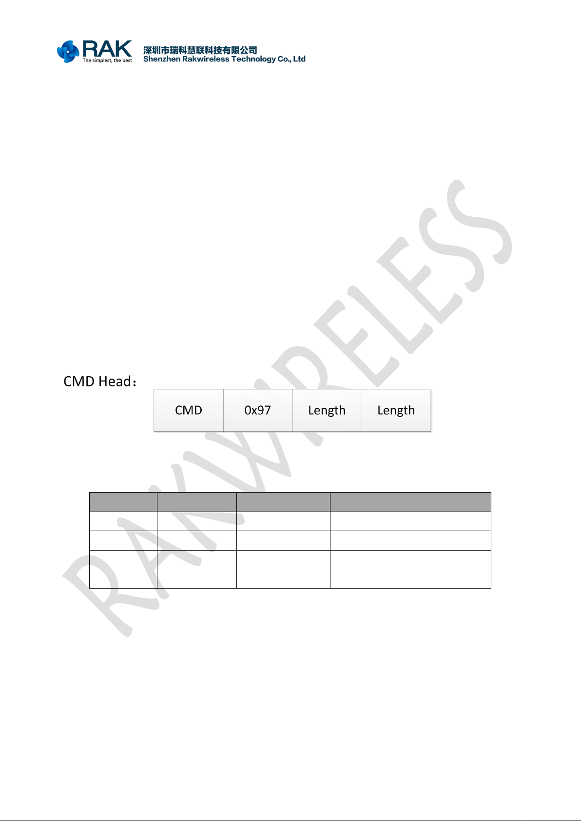
3.4.1 Command frame header.............................................................................................................5
3.4.2 Read Status..................................................................................................................................... 6
3.4.3 Read Data........................................................................................................................................ 7
3.4.4 Write Data....................................................................................................................................... 8
3.4.5 Command example...................................................................................................................... 9
3.4.6 Status Register............................................................................................................................. 12
3.4.7 Error code......................................................................................................................................12
3.5 Boot............................................................................................................................................................13
3.6 Power Mode.............................................................................................................................................13
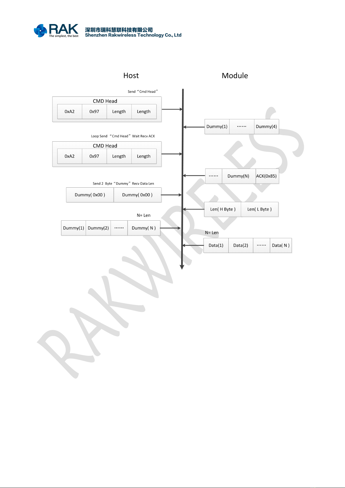
3.7 Operational Process.............................................................................................................................. 14
4. AT Command............................................................................................................................. 16
4.1 Module Management Commands....................................................................................................17
4.1.1 Initializing Module......................................................................................................................17
4.1.2 Checking Software Version...................................................................................................... 18
4.1.3 Setting Power Mode.................................................................................................................. 18
4.1.4 Reading Module Status.............................................................................................................19
4.1.5 Reset............................................................................................................................................... 19
4.1.6 Module firmware upgrade....................................................................................................... 20
4.2 Network Operation Commands.........................................................................................................21
4.2.1 Scanning Wireless Network..................................................................................................... 21
4.2.2 Getting Scanned Information..................................................................................................22
4.2.3 Setting Password.........................................................................................................................23

RAK411 PROGRAMMING MANUAL V1.7
COPYRIGHT ©
SHENZHEN RAKWIRELESS TECHNOLOGY CO., LTD
ETDX1602191815
3
4.2.4 Setting Channel...........................................................................................................................23
4.2.5 Connecting Wireless Network................................................................................................ 24
4.2.6 Configuring Static IP Address................................................................................................. 25
4.2.7 Setting DHCP Mode...................................................................................................................26
4.2.8 Connecting Network by Easyconfig...................................................................................... 27
4.2.9 Connecting Network by WPS..................................................................................................28
4.2.10 Getting Network Connection Status...................................................................................29
4.2.11 Querying module IP information.........................................................................................30
4.2.12 Getting Network Signal Strength........................................................................................ 31
4.2.13 DNS...............................................................................................................................................31
4.2.14 PING............................................................................................................................................. 32
4.2.15 AP Network Advanced Settings........................................................................................... 33
4.2.16 Setting Network Listening Intervals....................................................................................34
4.2.17 Disconnecting Current Wireless Network......................................................................... 34
4.3 Socket Operation Commands............................................................................................................ 35
4.3.1 TCP Server.....................................................................................................................................35
4.3.2 TCP Client...................................................................................................................................... 36
4.3.3 UDP Client.....................................................................................................................................37
4.3.4 UDP Server....................................................................................................................................38
4.3.5 UDP multicast ............................................................................................................................. 39
4.3.6 Query TCP server connections................................................................................................40
4.3.7 Closing Socket............................................................................................................................. 41
4.3.8 Sending Data................................................................................................................................42
4.3.9 Receiving Data............................................................................................................................. 43
4.4 Save Parameters Commands.............................................................................................................. 45
4.4.1 Storing Network Configuration Parameters....................................................................... 45
4.4.2 Storing Current Network Parameters....................................................................................46
4.4.3 Modifying Web Parameters.....................................................................................................47
4.4.4 Enabling Automatic Connection............................................................................................ 48
4.4.5 Starting Web Server...................................................................................................................49
4.4.6 Getting Saved Network Parameters...................................................................................... 50
5 Sales and Service....................................................................................................................... 54
6 Revision History......................................................................................................................... 55

RAK411 PROGRAMMING MANUAL V1.7
COPYRIGHT ©
SHENZHEN RAKWIRELESS TECHNOLOGY CO., LTD
ETDX1603021415
1
1 Overview
1.1 Module Introduction
RAK411 module is a Wi-Fi module that fully compliant with IEEE 802.11b/g/n wireless
standards, with internally integrated TCP / IP protocol stack, supporting numerous protocols
such as ARP, IP, ICMP, TCP, UDP, DHCP CLIENT, DHCP SERVER, DNS and other etc. It supports AP
mode, Station mode and Ad-hoc and mode. Users can easily and quickly use it to networking
and data transmission. Through SPI interface, the module’s maximum transmission rate is up to
2Mbps.
RAK411 supports storing parameters, and by the customer commands it determines
whether to enable automatic networking to realize easy networking and reduce time for system
to networking. The module has built-in WEB server, supporting wireless network parameters
configuration, supporting wireless firmware upgrade. It also supports WPS and EasyConfig
one-key networking, significantly reducing software development effort.
RAK411 has four power management modes, among which the minimum standby power
consumption is 2uA, fully meet customer’s requirement for low power design.
1.2 Device Features
Support IEEE 802.11b/g/n wireless standards
Support four-wire SPI interface
Support SPI Clock up to Maximum 16Mhz
Minimalist hardware peripheral circuit design
Support Station, Ad-hoc and AP modes
Support DHCP SERVER / DHCPCLIENT
Support OPEN, WEP, WPA-PSK, WPA2-PSK and WPS encryption
Support TCP, UDP protocols, with maximum 8 UDP/TCP connections
Support webpage-based parameter configuration
Support WPS and EasyConfig one-key to network connection
Support parameter storage, customer orders loading after boot
Support parameters store in Deep Sleep State, with connection time as
fastest as 300m
Support wireless upgrade firmware

RAK411 PROGRAMMING MANUAL V1.7
COPYRIGHT ©
SHENZHEN RAKWIRELESS TECHNOLOGY CO., LTD
ETDX1603021415
2
On-board ceramic antenna or U.FL antenna connector
Operating voltage: 3.3V
4 kinds power working modes, with minimum power consumption as
1-2uA
Small package size: 28.75mmX23.14mmX3.40mm
FCC, RoHS and CE compliant
1.3 Key Applications
Portable products
Home appliances and electrical appliances
Industrial sensors
Sales terminals
Buildings automation
Logistics and freight management
Home security and automation
Medical applications, such as patient monitoring, medical diagnostics
Metering (stop timing, measuring instruments, meters, etc.)

RAK411 PROGRAMMING MANUAL V1.7
COPYRIGHT ©
SHENZHEN RAKWIRELESS TECHNOLOGY CO., LTD
ETDX1603021415
3
2 Functional Description
2.1 HW Interface
Support clock 16MHz Maximum
Interface actual throughput up to 2Mbps
Four-wire SPI interface, support SPI data interrupt pin
2.2 Wireless Driver
Compliant with IEEE 802.11b/g/n standards
Support AP and STA Mode
Support WEP, WPA/WPA2-PSK encryption
Fast networking, allowing module to be added to network within 1 sec
after power up
Support WPS and EasyConfig one-key to network connection
Support wireless configuration and firmware upgrade
2.3 TCP/IP
DHCP Client and Server features
DNS Client and Server functions
TCP Client, TCP Server, UDP Client, UDP Server and Multicast functions
8-way socket applications
2.4 Power Consumption
The module supports four power consumption modes:
Full speed working mode, with approx 80mA average power consumption, peak current
less than 310mA
Power-saving mode, with approx 10mA average power consumption, peak current
<310mA, DTIM = 100ms
Deep sleep mode, with approx 5mA average power consumption, peak current <310mA,
DTIM = 100ms
Standby mode, with power consumption<2uA

RAK411 PROGRAMMING MANUAL V1.7
COPYRIGHT ©
SHENZHEN RAKWIRELESS TECHNOLOGY CO., LTD
ETDX1603021415
4
3 SPI Interface
RAK411 communicates with the host through a standard 4-wire SPI interface. SPI clock
supports maximum 16MHZ and optional SPI-INT pin. The SPI interface configuration diagram is
as follows:
3.1 Hardware Connection
3.2 SPI Timing Diagram
SPI_CS
SPI_CL
SPI_MO
SPI_MIS
CPOL = 0--------------------------------------SCK is idle in low level voltage
CPHA = 0--------------------------------------Data is latched on clock rising edge, while
transmitted on clock falling edge
MSB_FIRST--------------------------------------MSB is first sent8 BIT
MODE----------------------------------------------Data length is 8
bitsCS-----------------------------------------------Slave selective signal is effective low

RAK411 PROGRAMMING MANUAL V1.7
COPYRIGHT ©
SHENZHEN RAKWIRELESS TECHNOLOGY CO., LTD
ETDX1603021415
5
3.3 Interrupt Pin
RAK411 provides an optional INT pin, so that the host can quickly respond to module data
requests via the INT pin. The normal INT pin is low level voltage, when there is abnormal data to
be sent, the module pulls INT to high level. After the host receives the rising edge, the module
can read the data by sending read frames directly.After reading a package, INT pin goes low. If
there is data in the module needs to be sent to the host, the module will once again pull up INT
pin.
3.4 SPI Frame Format
The SPI basic operations are divided into three categories: read status, write data, and read
data.
3.4.1 Command frame header
The frame head is composed of three parts, CMD, Length, 0x97.
Field Bytes Value Instruction
CMD 1 0xA0-0xCD Command code for all commands
0x97 1 0x97 Fixed
Length 2 0-1416
The command and the length of the
data, the low byte in the front

RAK411 PROGRAMMING MANUAL V1.7
COPYRIGHT ©
SHENZHEN RAKWIRELESS TECHNOLOGY CO., LTD
ETDX1603021415
6
3.4.2 Read Status
Description:
1.The Host end loop sends the Head CMD to the module, and the sending
process requires a query if there is received ACK (0x85) .
2.If received CMD then stop the current Head ACK send.
3.Send 1 Dummy bytes for the subsequent status status.
4.Status is the status byte, the detail 3.4.6 status register.
CMD Head:
1.CMD fill in the read status command (0xA1).
2.0x97 fixed.
3.Length should fill in 0 because the current command does not include any
parameters.

RAK411 PROGRAMMING MANUAL V1.7
COPYRIGHT ©
SHENZHEN RAKWIRELESS TECHNOLOGY CO., LTD
ETDX1603021415
7
3.4.3 Read Data
Description:
1.The Host end loop sends the Head CMD to the module, and the sending
process requires a query if there is received ACK (0x85) .
2.If received CMD then stop the current Head ACK send.
3.Send 2 bytes Dummy for receiving len, the high byte in the front.
4.After the value of the len, the Dummy bytes of len are sent to receive the
following data.
CMD Head:
1.CMD fill in the read status command (0xA2).
2.0x97 fixed.
3.Length should fill in 0 because the current command does not include any
parameters.

RAK411 PROGRAMMING MANUAL V1.7
COPYRIGHT ©
SHENZHEN RAKWIRELESS TECHNOLOGY CO., LTD
ETDX1603021415
8
3.4.4 Write Data
Description:
1.The Host end loop sends the Head CMD to the module, and the sending
process requires a query if there is received ACK (0x85) .
2.If received CMD then stop the current Head ACK send.
3.Send the current command command code and the parameters of the data,
detailed reference 4 “command Daquan”.
CMD Head:
1.CMD fill in the command code to send, such as scanning the wireless network
command to fill in 0xA3, obtain the software version number command to fill
in 0xBE.
2.0x97 fixed.
3.Length should fill in the corresponding command parameter length, len
calculation method is sum of the command parameters in bytes, for example,
scanning wireless network command to "CMD" + "channel" + "SSID"
=4+4+32=40, access to software version number command CMD = 4. Detailed

RAK411 PROGRAMMING MANUAL V1.7
COPYRIGHT ©
SHENZHEN RAKWIRELESS TECHNOLOGY CO., LTD
ETDX1603021415
9
reference "4.2.1 scanning wireless network" and "4.1.2 query software version"
command.
3.4.5 Command example
Set the network channel command, channel set to 7
1.CMD to fill in the corresponding set channel command code 0xAB.
2.0x97 fixed.
3.Length the length of the corresponding commands is required.. Set the
parameters for the channel command to include the CMD field (4Byte) and the
channel field (4Byte), where 0x08 should be filled. Detailed reference to the
4.2.4 set up network channel command.
A complete command flow is divided into three parts:
1.Need to send host to write commands to the module. Command for “ setting up
network channel ”.
2.Host terminal is required to wait for the INT pin is high, or read the status
display data need to read.
3.The host is required to send the read data command to the module, and the module
returns the command to the host.Finally, the host determines whether the command
executes successfully by verifying the returned data.

RAK411 PROGRAMMING MANUAL V1.7
COPYRIGHT ©
SHENZHEN RAKWIRELESS TECHNOLOGY CO., LTD
ETDX1603021415
10

RAK411 PROGRAMMING MANUAL V1.7
COPYRIGHT ©
SHENZHEN RAKWIRELESS TECHNOLOGY CO., LTD
ETDX1603021415
11
Description:
1.The Host terminal loop sends the Head CMD to the module of the "set
channel" command code 0xAB, and the sending process requires a query
whether received ACK (0x85).
2.If received CMD then stop the current Head ACK send.
3.The command code for the current command and the parameter data (8Byte) of
the belt.. Detailed reference “4.2.4 network channel ”.
4.Need to wait for the execution of the command, and determine whether the
execution is successful. You can judge the INT pin is high, or read the status
command, read to Data_flag=1 (0x81), to determine whether the module data
need to read.Detail 3.4.6 status register.
5.The Host end loop sends the read status command code CMD to the Head
0xA1 to the module, and the sending process requires a query if there is
received ACK (0x85).
6.If received CMD then stop the current Head ACK send.
7.Send 1 Dummy bytes for the subsequent status status.
8.Determine the status byte Data_flag=1, then read the data read the command,
or read the state repeatedly.
9.Host end loop sends the read data command code CMD to the Head 0xA2 to
the module, and the sending process is required to query if there is received
ACK (0x85).
10.If received CMD then stop the current Head ACK send.
11.Send 2 Dummy bytes for receiving length, high byte before. The received
length should be 0x03 because the return value of the setup channel
command is only 3 bytes. Detailed reference to the “ 4.2.4 set up network
channel command”.
12.After obtaining the value of length equal to 0x03, send Dummy 0x03 bytes
for receiving subsequent data. Of the received data, the first two bytes are
code code, and the last byte bit command is executed by the status code, and
then the command is executed successfully. Detailed reference to the “ 4.2.4
set up network channel command”.

RAK411 PROGRAMMING MANUAL V1.7
COPYRIGHT ©
SHENZHEN RAKWIRELESS TECHNOLOGY CO., LTD
ETDX1603021415
12
3.4.6 Status Register
Description:
Here is the byte of status read, the last two bits representative the data type of module
feedback.
Bit7: SPI_STATUS
Bit6: reserve
Bit5: reserve
Bit4: reserve
Bit3: Send_full, Indicates that the module is unable to respond to the command
at this time, except for reading status and reading data
Bit 2 Upgrade_err, Upgrade error, need to reset the module
Bit1: Buffer_full=1, The internal data cache area of module is full, valid when
SPI_STATUS is 1
Bit0: Data_flag=1, Module has data to inform host (response of command or
received data), valid when SPI_STATUS is 1
3.4.7 Error code
When the command frame error, will prompt the error code returned,detailed as follows:
Code Description
-1
Parameter input error (parameter is unable to identify / missing parameter /
command is too long / other illegal parameters)
-11 System error (restart module)
-12 Fatal error (contact manufacturer)
Other Please refer to the following commands

RAK411 PROGRAMMING MANUAL V1.7
COPYRIGHT ©
SHENZHEN RAKWIRELESS TECHNOLOGY CO., LTD
ETDX1603021415
13
3.5 Boot
RAK411’s reboot time is about 210ms. After a normal start, the host sends the initialization
command, and the module will return start information:
ASCII------- Welcome to RAK411
HEX-------- 57 65 6C 63 6F 6D 65 20 74 6F 20 52 41 4B 34 31 31
3.6 Power Mode
RAK411 supports four power modes, shown as the following table:
Mode Control Part Wireless Part Wake-up Type Min Power
Consumption (AP)
0 Normal Normal No need 80mA
1 Sleep_Mode Power_Save No need 10mA
2 Deep_Sleep Power_Save SPI wake up 5mA
3 Deep_Sleep Shut_down
SPI wake up,
Reset
2uA
pwrmode=0-------------Mode 0
Module works under the maximum performance, control part and wireless part are fully
opened.
pwrmode=1-------------Mode 1
The control part enters into shallow sleep, the wireless part maintains the current connection
status, and enters a low-power mode. The communication is normal, but this will reduce
performance of module, the speed of sending and receiving is reduced.
pwrmode=2-------------Mode 2
The control part enters into a deep sleep, the wireless part maintains the current wireless
connection status, and enters a low-power mode.The remote data or host initiates
communications to wake up control part, then enters into mode 1. If no sending and receiving
data, it automatically enters into Mode 2.

RAK411 PROGRAMMING MANUAL V1.7
COPYRIGHT ©
SHENZHEN RAKWIRELESS TECHNOLOGY CO., LTD
ETDX1603021415
14
pwrmode=3------------Mode 3
When enters into this mode, module firstly saves current connective status to RAM, and
shuts down the power of wireless part, then control part enters into deep state. In this state,
module cannot respond to any command or wireless data, lowering consumption to
minimum.User can initiate communication or reset module. It enters into mode 0 by default after
start.
3.7 Operational Process
RAK411 SPI command operation feature completes a few basic steps of WIFI communication,
including network scanning, joining network and obtaining an IP address, and eventually
establishing Socket communication. RAK411 provides a variety of convenient operation to
implement networking, so that customers can easily complete the network configuration, and
concentrate on the management of socket and their own data protocols.
To realize automatic networking management, customers can take advantage of WEB, WPS
and EasyConfig configuration features. The module will automatically store paramenters after a
successful configuration, and these automatic networking commands can be used any time,
letting the module automatically complete networking operation, and returning the results.
The basic operation of the process is as follows:

RAK411 PROGRAMMING MANUAL V1.7
COPYRIGHT ©
SHENZHEN RAKWIRELESS TECHNOLOGY CO., LTD
ETDX1603021415
15

RAK411 PROGRAMMING MANUAL V1.7
COPYRIGHT ©
SHENZHEN RAKWIRELESS TECHNOLOGY CO., LTD
ETDX1603021415
16
4. AT Command
The SPI commands are divided into four parts:module management commands, network
operations commands, socket operation commands, and parameters storing commands, shown
as the followings:
Command Description
Module Management Commands
rak_sys_init Initialize module, read boot information
rak_get_version Check software version
rak_setpwrmode Set module power mode
rak_read_status Read module status information
rak_reset Reset module
rak_set_upgrade Firmware upgrade for modules
Network Operation Commands
rak_scan Scan wireless networks
rak_getscan Reads a specified number of scan results
rak_set_psk Set network password
rak_set_channel Set network channel
rak_connect Connect wireless network
rak_set_ipstatic Configure Static IP Address
rak_ipconfig_dhcp Setting DHCP Mode
rak_easy_config Connecting network by Easyconfig
rak_wps Connecting Network by WPS
rak_get_con_status Get network connection status
rak_ipconfig_query Check module IP information
rak_get_rssi Get network signal strength of module
rak_dns DNS
rak_ping Ping hosts in the network
rak_apconfig AP Network Advanced Settings
rak_set_listen Set network listening intervals
rak_disconnect Disconnect the current wireless network
Socket Operation Commands
rak_udp_client Establish UDP client
rak_udp_server Establish UDP Server
rak_tcp_client Establish TCP client
rak_tcp_server Establish TCP Server

RAK411 PROGRAMMING MANUAL V1.7
COPYRIGHT ©
SHENZHEN RAKWIRELESS TECHNOLOGY CO., LTD
ETDX1603021415
17
rak_socket_close Close an opened socket handle
rak_get_tcps
Gets the number and the information for the
tcp sever to connect to client
rak_send_data Send data to an opened socket handle
rak_read_data
Read command returns / network data /
network information
Save parameters commands
rak_storeconfig_data Store network configuration parameters
rak_storeconfig Store the current network parameters
rak_web_store Store web server built-in parameters
rak_auto_connect Enable automatically connecting
rak_start_web Start web server and configure module
rak_get_storeconfig Get saved network parameters
rak_get_webconfig Get web server built-in parameters
4.1 Module Management Commands
4.1.1 Initializing Module
Command:
rak_sys_init
Syntax:
uint32_t cmd;
Parameter:
Parameter Bytes Value Description
Cmd 4 0xA0,0x00,0x00,0x00 Command Code
Description:
It is used to initialize module, and read boot information.
Return Value:
Parameter Bytes Value Description
<CODE> 2 0xA0,0x00 Response Code
<DATA> 17 Welcome to RAK411 Welcome string
<STATUS> 1 0 Command successful
-2 Command failed
Table of contents
Other RAK Wireless Router manuals