RAKwireless RAK4200 User manual

RAK4200 Breakout Module
2
Table of Contents
1 Product Overview.................................................................................................................................. 3
1.1 Product Background....................................................................................................................... 3
1.2 Product Background....................................................................................................................... 3
2 Prerequisites........................................................................................................................................... 4
2.1 Hardware tools.................................................................................................................................4
2.2 Software tools.................................................................................................................................. 4
3 Configuration.......................................................................................................................................... 5
3.1 Interfacing with the RAK4200 Evaluation Board........................................................................ 5
3.2 Connecting to The Things Network (TTN).................................................................................. 8
3.2.1 Adding an Application........................................................................................................ 8
3.2.2 Registering a device........................................................................................................ 10
4 Revision History...................................................................................................................................19
5 Document Summary........................................................................................................................... 19

RAK4200 Breakout Module
3
1Product Overview
1.1 Product Background
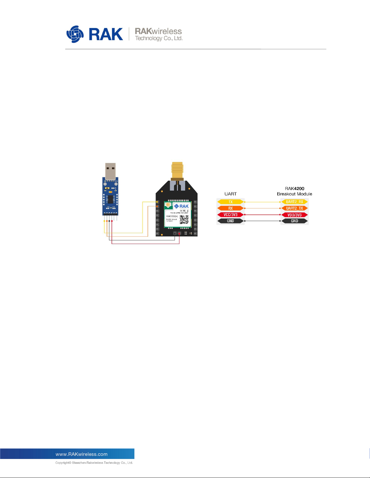
RAK4200 Breakout Module is specifically designed to allow easy excess to the pins on
the module in order to simplify development and testing. The breakout board utilized is
of an Xbee form factor and its main purpose is to allow the RAK4200 stamp module form
factor pinout to be transferred to 2.54mm headers.
The module itself has the RAK4200 at its core, integrating an STM32L071 MCU and a
SX1276 LoRa® chip. It has Ultra-Low Power Consumption of 1.5uA in sleep mode, high
LoRa® max output power (19dBm) in work mode.
The module complies with LoRaWAN® 1.0.2 protocols. It also supports Lora® Point to
Point communication.
The RF communication capabilities of the module make it suitable for a variety of
applications in the IoT field such as home automation, sensor networks, building
automation, personal area networks applications (health/fitness sensors and monitors,
etc.).
Figure 1 | RAK4200 LPWAN Breakout Module
1.2 Product Background
LPWAN module for Smart City, Smart Agriculture, Smart Industry
I/O ports: UART/I2C/GPIO
Temperature range: -40°C to +85°C
Frequency range: 863–870MHz (EU) / 902–928MHz (US), ISM and SRD systems
Low-Power Wireless Systems with 7.8kHz to 500KHz Bandwidth
Core: ARM 32-bit Cortex - M0+ with MPU
Up to 128KB flash memory with ECC
20KB RAM

RAK4200 Breakout Module
4
2Prerequisites
The following two sections will provide a list of the components and tools you need in
order to get started with the development board. Some of those are included in the
package, others you need to provide yourself.
2.1 Hardware tools
RAK4200 LPWAN Evaluation Board (provided) – including LoRa® antenna, Dupont
lines (13x)
USB to UART converter – CH340 for example (not provided)
Gateway in Range, for testing (not provided)
Windows PC (not provided)
Emulator Kit (not provided)
2.2 Software tools
RAK Serial tool
CH340 Drivers
The Things Network account (create here)

RAK4200 Breakout Module
5
3Configuration
3.1 Interfacing with the RAK4200 Evaluation Board
Warning
Before powering the RAK4200 Breakout Module, make sure you have installed the
included LoRa® Antenna. Not doing so might damage the board.
Connect your USB to UART converter to the pin header on the RAK4200 via a set of 4
dupont lines. Use Figure 2 for reference on wiring the device properly.
Figure 2 | Powering up and interfacing with the board
Go to your Device Manager by pressing: Windows + R and typing devmgmt.msc or
search in the Start Menu.
Look for Ports (COM & LPT) and Find the name USB-SERIAL CH340 and take note of
the COM Port Number as you will need it to connect with the board. You might have
another model number but the wording “USB-SERIAL” should be present in some form.
Note
Windows 10 should recognize the board and automatically install drivers, however if it is
missing in the COM & LP ports list you need to manually install the CH340 Drivers.

RAK4200 Breakout Module
6
Figure 3 | COM port settings

RAK4200 Breakout Module
7
Open the RAK Serial Port Tool. Select the COM Port number (the one you noted in the
previous step) and set the Baud Rate to 115200. Click “OPEN” and you should be
connected to the board and be able to send commands.
Figure 4 | Configuring the RAK Serial tool

RAK4200 Breakout Module
8
3.2 Connecting to The Things Network (TTN)
The Things Network is about enabling low power Devices to use long range Gateways to
connect to an open-source, decentralized Network to exchange data with Applications.
Learn more about the Things Network here.
Log into your TTN account and go to the Console page:
Figure 5 | TTN console main page
3.2.1 Adding an Application
Once in the console you will notice that it is split in two large sections. We are
only going to be utilizing the "APPLICATIONS" section for the purpose of this
tutorial. Access it by clicking anywhere in rectangle.
Figure 6 | Adding an Application
Click the "add application" button and you will be greeted by the window in
Figure 7.

RAK4200 Breakout Module
9
Figure 7 | Application parameters
Here are the things that you should take note in adding an application:
Application ID - this will be the unique id of your application in the Network. Please
note that characters should be in lower case, no spaces are allowed.
Description - this is a short and concise human readable description of your
application.
Application EUI - this will be generated automatically by The Things Network for
convenience and is a unique identifier of your application used for authentication of
devices
Handler Registration - handler you want to register this application to.
Fill in the Application ID and Description fields and leave the rest as is.
Click “Add application”
Upon successful application you should see the Application Overview page (Figure 8).

RAK4200 Breakout Module
10
Figure 8 | Application Overview page and Device registration
3.2.2 Registering a device
Now we need to add our actual device (RAK4200). Refer to Figure 8 again and
press the “register device” button that is marked with the red rectangle. Now
you need to set some device parameters (Figure 9)

RAK4200 Breakout Module
11
Figure 9 | Device parameters
Here are the things that you should take note in registering your device:
Device ID - this is the unique identifier for your RAK4200 EVB within the
particular application. You need to enter this manually.
Device EUI - this is the unique identifier for your device in the network.
You can change it later.
App Key – this key will be used to secure the communication between
the device and the network.
App EUI – a unique identifier of the Application that you are registering
the device within.
Populate the Device ID and Device EUI (generate a random one by pressing the
arrows) fields and leave the rest as is.
Click “Register”
Upon successful device registration you should see the Device Overview page
(Figure 10).

RAK4200 Breakout Module
12
Figure 10 | Device Overview page
Take note of the Activation Method which is set to OTAA by default (Figure 10).
This is one of two options, ABP being the second one. We will provide
instructions on both methods in the following sections, starting with OTAA.
OTAA mode
OTAA stands for Over The Air Activation. We will not delve into details, however
the most important thing from practical perspective is that a device needs to have
the 3 parameters (Device EUI, Application EUI, and App Key) we already
explained in brief in the following section set correctly in order for the LoRa®
Server to allow it to access to the network.
These can be obtained from the Device Overview page, where they are grouped
one after the other for convenience (Figure 11).

RAK4200 Breakout Module
13
Figure 11 | OTAA parameters set
As these are randomly generated by TTN we need to update our RAK4200 with
their values in order to be able to register it with the network.
Note
For the sake of this tutorial we will use an example that works withing the EU868
band in LoRa® Class A device mode
As our device is already powered and connected to our PC and we can configure
it with the RAK Serial tool we need only execute a set of commands in order to
update it with the configuration parameters.
Note
Execute the following commands one by one and in the order given.
Set the device join mode to OTAA:
at+set_config=lora:join_mode:0
Set the device to Class A:

RAK4200 Breakout Module
14
at+set_config=lora:class:0
Set the device region to EU868:
at+set_config=lora:region:EU868
Executing the set of commands above in order should result in a command
output in the RAK Serial tool much like the one in Figure 12:
Figure 12 | Device Setup - 1

RAK4200 Breakout Module
15
Next, we need to set the authentication parameters. You can copy those from the
Device Overview page (Figure 11). Replace the XXXX in the commands below
with your particular set of symbols.
Set the Device EUI:
at+set_config=lora:dev_eui:XXXX
Set the Application EUI:
at+set_config=lora:app_eui:XXXX
Set the App Key:
at+set_config=lora:app_key:XXXX
Note
Execute the following commands one by one and in the order given.

RAK4200 Breakout Module
16
Executing the set of commands above in order should result in a command
output in the RAK Serial tool much like the one in Figure 13 (the values there are
just an example):
Figure 13 | Device Setup - 2
Reboot the device:
at+set_config=device:restart

RAK4200 Breakout Module
17
Join the network
at+join
Figure 14 | Device successful join and test data
If you look at Figure 14 you will see what you should expect as output after a
successful joining of the network. The device will report the join mode (OTAA in
this case) and the parameters (Device EUI, Application EUI, and App Key) it is
using for the join procedure. Finally, the successful joining to the network will be
reported.
This is also reflected in the Device Overview page in the TTN console (Figure 15),
where the last seen status of the node is updated:

RAK4200 Breakout Module
18
Figure 15 | Device real time status update after authentication
As your device has now been authenticated it can now send uplink frames.
Send an Uplink LoRa® frame
at+send=lora:2:0123456789
Additionally, you should also see this in the TTN console provided you have
access to a Gateway. The join request and join accept frames marked with the
yellow and green lightning symbol and the blue triangle being the uplink frame
we sent last as an example (Figure 16).
Figure 16 | Device real time frame data

RAK4200 Breakout Module
19
4Revision History
Revision
Description
Date
1.0
Initial Release
2020-04-24
5Document Summary
Prepared by
Checked by
Approved by
Vladislav
About RAKwireless:
RAKwireless is a pioneer in providing innovative and diverse Cellular and LoRaWAN connectivity
solutions for both Edge and Gateway IoT devices. We believe that through easy to use and
modular designs we can accelerate the time to market for various IoT Applications in order to
optimize system deployment in both Developer and Commercial settings.
Other manuals for RAK4200
1
Table of contents
Other RAKwireless Motherboard manuals