2
www.DentalEZ.com 866-DTE-INFO (opt 4)
2
www.DentalEZ.com
Badger LF User Manual
This manual contains installation, operation,
care, and repair instructions and user service
information for the RAMVAC® Utility Badger LF
dental vacuum system.
The main purpose of the Badger LF is to provide
a positive displacement, oil-less dry vacuum
system intended for use in a dental facility and
to be used by trained professional dental care
personnel only.
Badger LF is designed to provide trouble-free service
when installed, operated and cared for according to
the procedures set forth in this User Manual.
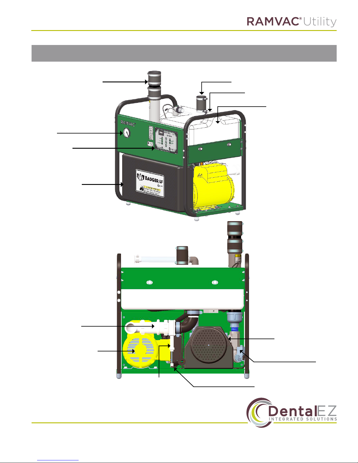
Vacuum is supplied to the system by a durable oil-
less rotary vane pump. A space-saving integrated
separation tank keeps liquid and foam out of the
pump. The E2 control provides precise electrical
control over run-time and shutdown operations
while vacuum is maintained at a uniform level by
the RAMVAC vacuum level control valve.
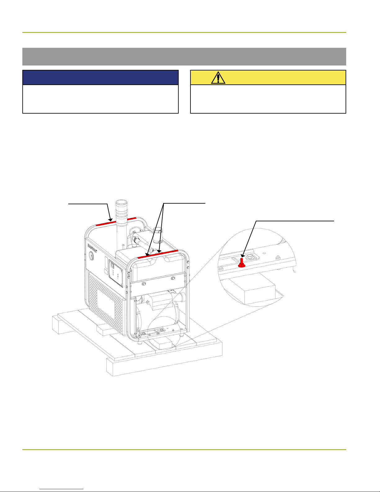
To ensure proper installation of the Badger
LF, carefully read all instructions contained
in this manual prior to installing, operating,
and servicing. For safety, pay close attention
to all notices, warnings, cautions and notes.
Section I Introduction
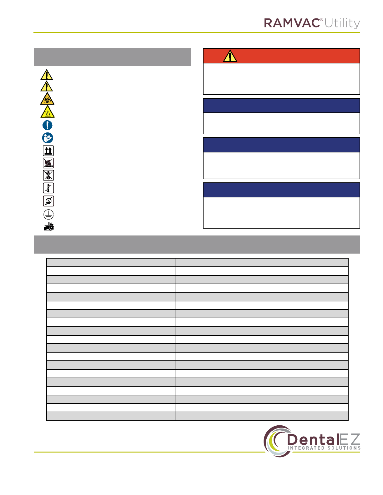
Safety Information
Classications
After the Badger LF is installed, please review the
features, operation procedures and care guide-
lines with the doctor's sta. Leave this manual in
the doctor's oice for future reference.
RAMVAC vacuum units are certied to ANSI/AAMI,
EX606-0-1:2005(R2012) and certied to CAN/CSA
Standard C22.2 No. 60601-11:08, and comply with
NFPA 99c Level 3 vacuum requirements, and are
manufactured in a FDA Registered ISO 13485:2003
certied facility.
– Type of protection against electric shock:
Class 1 Equipment
– Degree of protection against the ingress of
water: Ordinary
Here’s what you need to do to insure the safety
potential of this equipment is achieved:
• Make sure your equipment is installed ac-
cording to our written instructions and the
Installation Checklist is completed. If you have
purchased your RAMVAC from an authorized
dealer, the dealer is responsible for presenting
you with the completed checklist.
• Exhaust from dental vacuum systems can be
hazardous. Make sure the exhaust pipe is ter-
minated outside your building according to our
written instructions.
• Nitrous oxide and oxygen can be safely scav-
enged in the small concentrations typically
encountered in dental analgesia. The additional
air drawn into a properly installed and operated
Vacuum Unit will dilute these agents.
• Never use your RAMVAC to remove pure nitrous
oxide, oxygen or other oxidizing agents directly
from storage vessels or supply hoses. Large
concentrations may cause a re in the Vacuum
Unit and may cause an exhaust hazard.
• Never use this equipment in an OXYGEN RICH
ENVIRONMENT. Large concentrations may
cause a re in the Vacuum Unit and may cause
an exhaust hazard.
• Never use your RAMVAC for housekeeping
functions.
• Never use your RAMVAC to collect lab dust.