R&M CMX 007 Operation instructions

English
Original Instruction
INSTALLATION INSTRUCTION
TMU Upgrade Kit
020131en / Revision C
2013-03-20

TABLE OF CONTENTS
1 INTRODUCTION................................................................................................................................... 3
1.1 About this manual......................................................................................................................... 3
1.2 About the upgrade kit usage......................................................................................................... 3
1.3 Waste treatment and recycling of removed material...................................................................... 3
2SAFETY................................................................................................................................................. 4
2.1 Before starting to work at the site.................................................................................................. 4
2.2 Main switch and emergency stop buttons...................................................................................... 4
2.3 After working at the site................................................................................................................. 4
3DESCRIPTION OF THE UPGRADE KIT............................................................................................... 5
3.1 Parts included in the kit................................................................................................................. 5
3.2 Required tools............................................................................................................................... 6
3.3 Terminal connections.................................................................................................................... 6
3.4 DIP switches................................................................................................................................. 7
3.5 EMC filter...................................................................................................................................... 8
4INSTALLATION..................................................................................................................................... 9
4.1 Old frequency converter removal.................................................................................................. 9
4.2 Control voltage front resistors....................................................................................................... 12
4.3 New frequency converter installation............................................................................................. 12
5 COMMISSIONING................................................................................................................................. 17
5.1 Old inverter parameter settings..................................................................................................... 17
5.2 Driving frequency table selection................................................................................................... 17
5.3 S1 Maximum driving frequency..................................................................................................... 18
5.4 S2 Minimum driving frequency...................................................................................................... 20
5.5 S3 Acceleration and deceleration ramp time................................................................................. 23
5.6 S4 Control mode and slowdown mode.......................................................................................... 24
5.7 S5–S10 Motor parameters............................................................................................................ 25
5.8 Testing the trolley functions........................................................................................................... 26
6 TROUBLESHOOTING........................................................................................................................... 27
6.1 Purpose of troubleshooting........................................................................................................... 27
6.2 Problems and solutions................................................................................................................. 27
7 ELECTRICAL DRAWING...................................................................................................................... 28
R&M Materials Handling, Inc.
4501 Gateway Boulevard
Springfield, Ohio 45502
P.: (937) 328-5100
FAX: (937) 325-5319
2/28 R&M Materials Handling, Inc. reserves the right to alter or amend the above information without notice.

1 INTRODUCTION
1.1 About this manual
This manual offers installation and commissioning instructions of CMX 007 frequency converter replacement to
ControlMaster®NXT 003 .
As a maintenance technician, taking the time to read this manual will help you easily adopt the replacement
procedures. Note that this manual is not intended as a substitute for proper training.
1.2 About the upgrade kit usage
This upgrade kit is designed only for CMX 007 frequency converter which is mounted in a
TROLLEY MOTOR UNIT (TMU) in chain hoist crane. It is not designed for wire rope hoist
application. There is a different replacement kit available for the Wire Rope Hoist application.
There is no replacement kit available for chain hoist hoisting application. In case of brake
down, the complete chain hoist must be replaced with a new one.
Parameters for the new ControlMaster®NXT 003 frequency converter have NOT BEEN SET
UP at the factory. Please make sure that you SET UP the DIP switches according the
following instructions before start-up.
1.3 Waste treatment and recycling of removed material
The removed parts and packaging material shall be recycled according to local regulations. We recommend
recycling the frequency converter’s aluminum heat sink separately.
R&M Materials Handling, Inc.
4501 Gateway Boulevard
Springfield, Ohio 45502
P.: (937) 328-5100
FAX: (937) 325-5319
3/28 R&M Materials Handling, Inc. reserves the right to alter or amend the above information without notice.

2 SAFETY
2.1 Before starting to work at the site
Before starting any work on the crane:
• Familiarize yourself with the equipment and its user instructions.
• Find out the location of the main switch and the emergency stop buttons.
•Evaluate the risks of the site and try to minimize them.
• Inform the site responsible that you will be working on the crane.
• Restrict access to the working area, if possible.
• Prevent unintentional use of the crane.
• Ensure that you have all the appropriate personal protection equipment. Use them as required.
2.2 Main switch and emergency stop buttons
Lock and tag the main switch when you need to switch it off during your work.
WARNING Be aware of the main isolation switch functionality.
Even though one switch is turned off, there may still be voltage in some
parts of the product.
2.3 After working at the site
Ensure that you leave the site in a safe condition:
• Ensure that the work area is clean.
• Remove any locks/tags from switches.
•Ensure that the crane functions normally.
• Inform the site responsible that you have finished the work.
R&M Materials Handling, Inc.
4501 Gateway Boulevard
Springfield, Ohio 45502
P.: (937) 328-5100
FAX: (937) 325-5319
4/28 R&M Materials Handling, Inc. reserves the right to alter or amend the above information without notice.
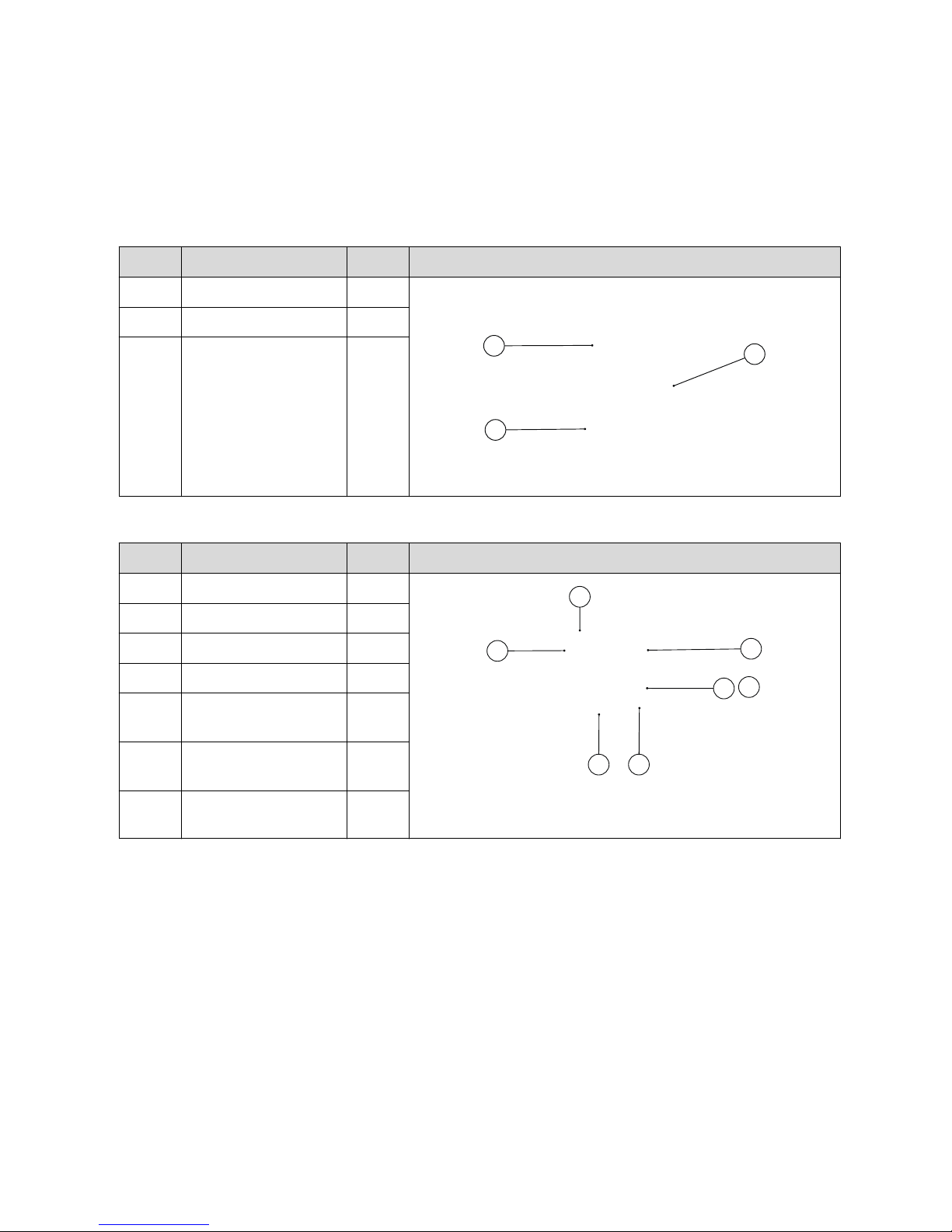
3 DESCRIPTION OF THE UPGRADE KIT
3.1 Parts included in the kit
Part Name Qty. Image
Part 1 Frequency converter 1 pcs
1
2
3
Part 2 Mounting rack 1 pcs
Part 3 Installation accessory 1 pcs
INSTALLATION ACCESSORY
Part Name Qty. Image
Part 4 Cable tie 3 pcs
47
5
6 10
89
Part 5 Wire marker set 1 pcs
Part 6 Allen key 1 pcs
Part 7 Cleaning pad 1 pcs
Part 8 Wire end ferrule 1.5
mm2
5 pcs
Part 9 Wire end ferrule 2.5
mm2
5 pcs
Part 10 Counter sunk flathead
screw M5 x 8
3 pcs
R&M Materials Handling, Inc.
4501 Gateway Boulevard
Springfield, Ohio 45502
P.: (937) 328-5100
FAX: (937) 325-5319
5/28 R&M Materials Handling, Inc. reserves the right to alter or amend the above information without notice.

3.2 Required tools
Item
No
Name Image
1 Screwdriver, slot-head 3.5 x 0.6 mm
3
12
4
65
2 Screwdriver, Phillips No. 2 (PH2)
3 Wire cutters
4 Socket wrench, 8 mm
5 Crimping tool for wire end ferrules
6 Wire strippers
3.3 Terminal connections
The following table describes the differences between the terminals of CMX 007 and ControlMaster®NXT
003 .
Description of terminal CMX
007 Terminal X1
ControlMaster®NXT
003 Power terminals
Protective earth 1 PE
Power supply, phase 1 2 L1
Power supply, phase 2 3 L2
Power supply, phase 3 4 L3
Motor supply, phase 1 5 U
Motor supply, phase 2 6 V
Motor supply, phase 3 7 W
Control board terminals
Drive command, direction1 8 1
Drive command, direction 2 9 2
Speed 2 / Acceleration command 10 3
Control voltage, common 11 7
Terminals 4, 5 and 6 in ControlMaster®NXT 003 control board are not used.
R&M Materials Handling, Inc.
4501 Gateway Boulevard
Springfield, Ohio 45502
P.: (937) 328-5100
FAX: (937) 325-5319
6/28 R&M Materials Handling, Inc. reserves the right to alter or amend the above information without notice.

3.4 DIP switches
CMX 007 has 4 groups of DIP switches (S1-S4), whereas ControlMaster®NXT has 10 groups of DIP switches
(S1-S10).
The correct DIP switch settings for ControlMaster®NXT 003 can be found in Chapter 5: “Commissioning”.
CMX 007 ControlMaster®NXT 003
Switch Description Description Switch
S1
S2
S3
S4
ON
1 2 3 4
ON
1 2 3 4
ON
1 2 3 4
ON
1 2 3 4
DIP DIP DIP
DIP
1212
12
1231 231 23
1231 231 2312
S1 S2 S3 S4 S5
S6 S7 S8 S9 S10
10
10
S1 Maximum driving frequency Maximum driving frequency S1
S2 Minimum driving frequency Minimum driving frequency S2
S3 Acceleration and deceleration ramp times Acceleration and deceleration ramp times S3
S4 Control mode and motor type Control method and slowdown mode S4
Limit operations S5
Voltage at low frequencies (U/f curve) S6
Current limit S7
Start and stop current S8
Motor nominal frequency S9
Terminal DI6 operation S10
R&M Materials Handling, Inc.
4501 Gateway Boulevard
Springfield, Ohio 45502
P.: (937) 328-5100
FAX: (937) 325-5319
7/28 R&M Materials Handling, Inc. reserves the right to alter or amend the above information without notice.
3.5 EMC filter
CMX 007 has an external EMC filter package (KC310 / KC330), whereas ControlMaster®NXT 003 has an
internal EMC filter in the power supply. By default, the EMC level of the frequency converter is set to N by the
manufacturer.
If the mains network is non-grounded (IT-network), the ControlMaster®NXT 003 frequency converter’s EMC
level must be changed to 0 by removing the filter capacitor disconnection screw.
Verify the type of electrical supply network from original electrical drawings.
DANGER
5 MIN
1 2 3 4 5 6 7 8 9 10 11
OK
R&M Materials Handling, Inc.
4501 Gateway Boulevard
Springfield, Ohio 45502
P.: (937) 328-5100
FAX: (937) 325-5319
8/28 R&M Materials Handling, Inc. reserves the right to alter or amend the above information without notice.
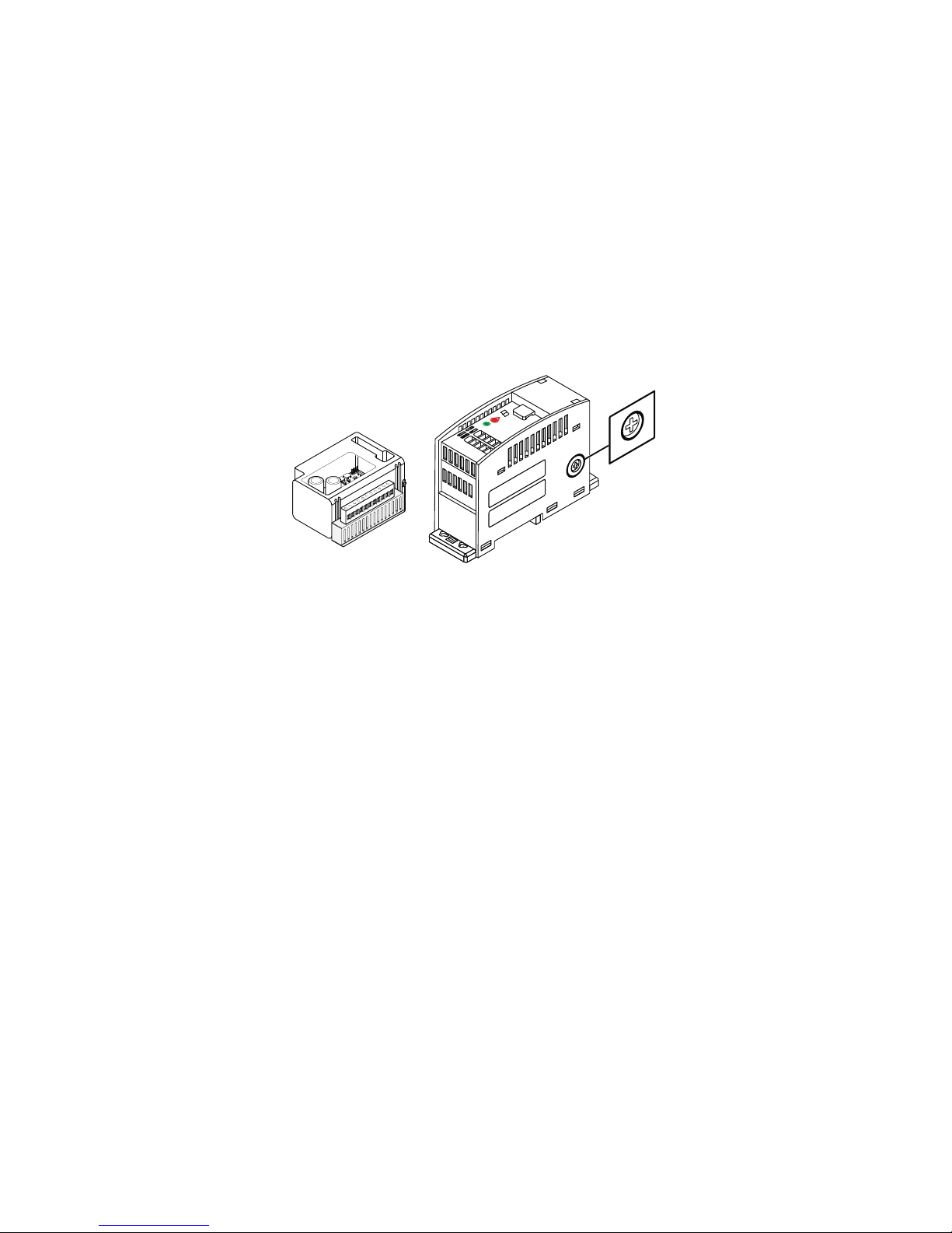
4 INSTALLATION
Before installation. After installation.
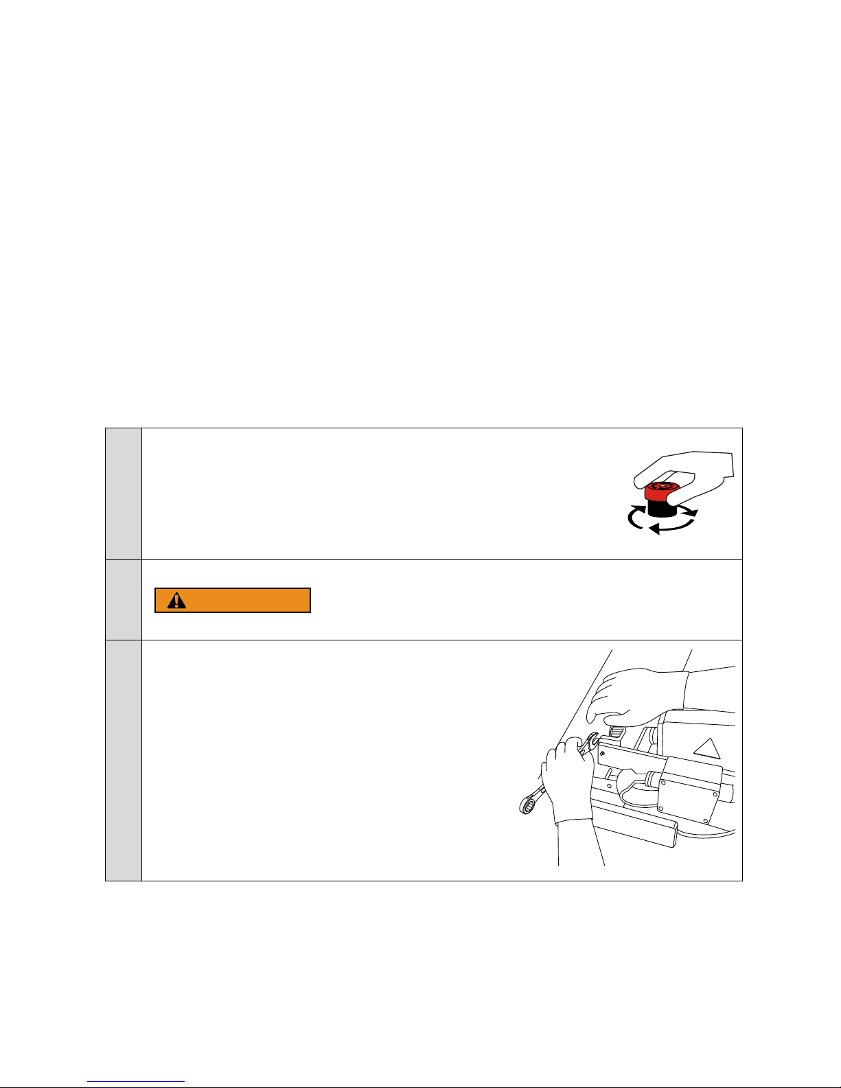
4.1 Old frequency converter removal
1If the trolley is operable (not broken), record the trolley driving directions.
2Push the main power off from the pendant or radio controller.
WARNING High voltage inside the Frequency converter.
Wait for at least five minutes after the voltage supply has been
switched of before taking any service actions.
3Remove the festoon electric connection box (if installed)
R&M Materials Handling, Inc.
4501 Gateway Boulevard
Springfield, Ohio 45502
P.: (937) 328-5100
FAX: (937) 325-5319
9/28 R&M Materials Handling, Inc. reserves the right to alter or amend the above information without notice.

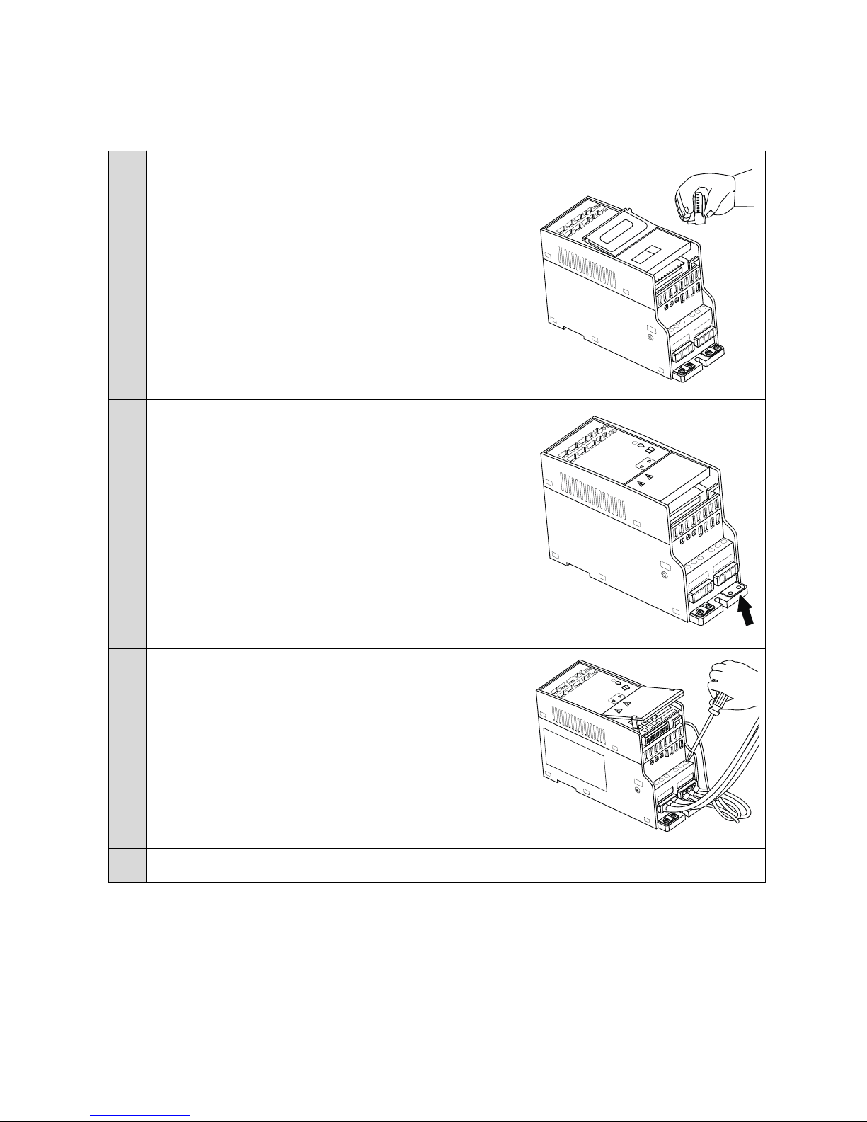
4Remove the motor connection box lid.
5Record the dip-switch settings from the CMX 007 frequency
converter.
On pageOld inverter parameter settings (page 17) you can
find an empty table where to write the settings.
6Remove the wire terminal by pulling. Remove the CMX 007 .
7Remove wires from the terminal one at the time.
R&M Materials Handling, Inc.
4501 Gateway Boulevard
Springfield, Ohio 45502
P.: (937) 328-5100
FAX: (937) 325-5319
10/28 R&M Materials Handling, Inc. reserves the right to alter or amend the above information without notice.

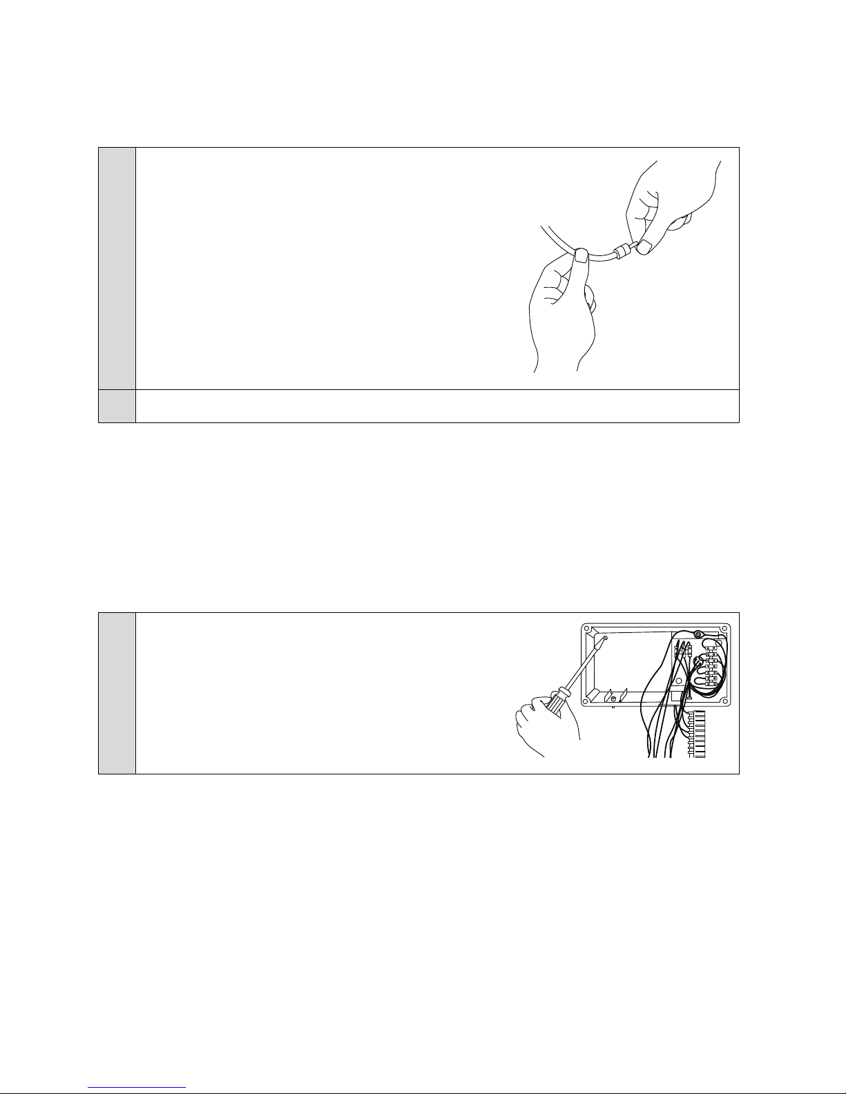
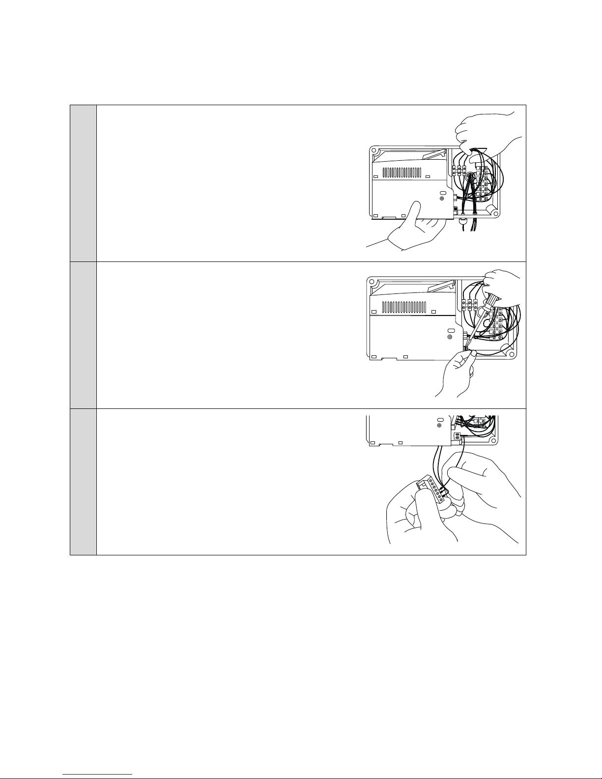
8Cut the wire. Make sure you leave as much length for the
wire as you can.
9Strip the wire end from the length of 10 mm.
10 Connect the end ferrule to the wire end.
R&M Materials Handling, Inc.
4501 Gateway Boulevard
Springfield, Ohio 45502
P.: (937) 328-5100
FAX: (937) 325-5319
11/28 R&M Materials Handling, Inc. reserves the right to alter or amend the above information without notice.
11 Mark the wire with markers. Use installation mandrel for easy
installation.
12 Do steps 5-9 to the rest of the wires.
4.2 Control voltage front resistors
The TMU should not have front resistors. However, if they are present, they must be removed. Do not mix the
order of the wires.
If the front resistors are not removed or by-passed, the control inputs on the
ControlMaster®NXT 003 frequency converter will not be activated, even though voltage can
be measured with a multimeter.
4.3 New frequency converter installation
1Install the bottom plate. Use the 2 flat head screws delivered
with the package.
R&M Materials Handling, Inc.
4501 Gateway Boulevard
Springfield, Ohio 45502
P.: (937) 328-5100
FAX: (937) 325-5319
12/28 R&M Materials Handling, Inc. reserves the right to alter or amend the above information without notice.
2Remove the input wire terminal from the ControlMaster®NXT
003 frequency converter.
S6 S7 S8 S9 S10
S1 S5
S4
S3
S2 10
10
3Remove the grounding wire connector. See image. Leave the
other in place. The inverter doesn't fit into the motor
connection box otherwise.
S6 S7 S8 S9 S10
S1 S5
S4
S3
S2 10
10
OK
4Connect the frequency converter power supply wires; L1, L2,
L3 and motor power supply wires; U,V,W.
S6 S7 S8 S9 S10
S1 S5
S4
S3
S2 10
10
OK
DANGER
5Set the correct dip switch settings according to commissioning tables.
R&M Materials Handling, Inc.
4501 Gateway Boulevard
Springfield, Ohio 45502
P.: (937) 328-5100
FAX: (937) 325-5319
13/28 R&M Materials Handling, Inc. reserves the right to alter or amend the above information without notice.
6Push the new frequency converter into the c-rail. Leave the
input lid open.
7Install the ground wire.
8Install the control wires (1,2,3 and 7) into the input terminal.
R&M Materials Handling, Inc.
4501 Gateway Boulevard
Springfield, Ohio 45502
P.: (937) 328-5100
FAX: (937) 325-5319
14/28 R&M Materials Handling, Inc. reserves the right to alter or amend the above information without notice.

9Push the input terminal into ControlMaster®NXT 003 . And
close the lid.
10 Fold the wires inside the box. Secure the wires with cable
ties. The image on the right shows how the final assembly
should look alike.
R&M Materials Handling, Inc.
4501 Gateway Boulevard
Springfield, Ohio 45502
P.: (937) 328-5100
FAX: (937) 325-5319
15/28 R&M Materials Handling, Inc. reserves the right to alter or amend the above information without notice.
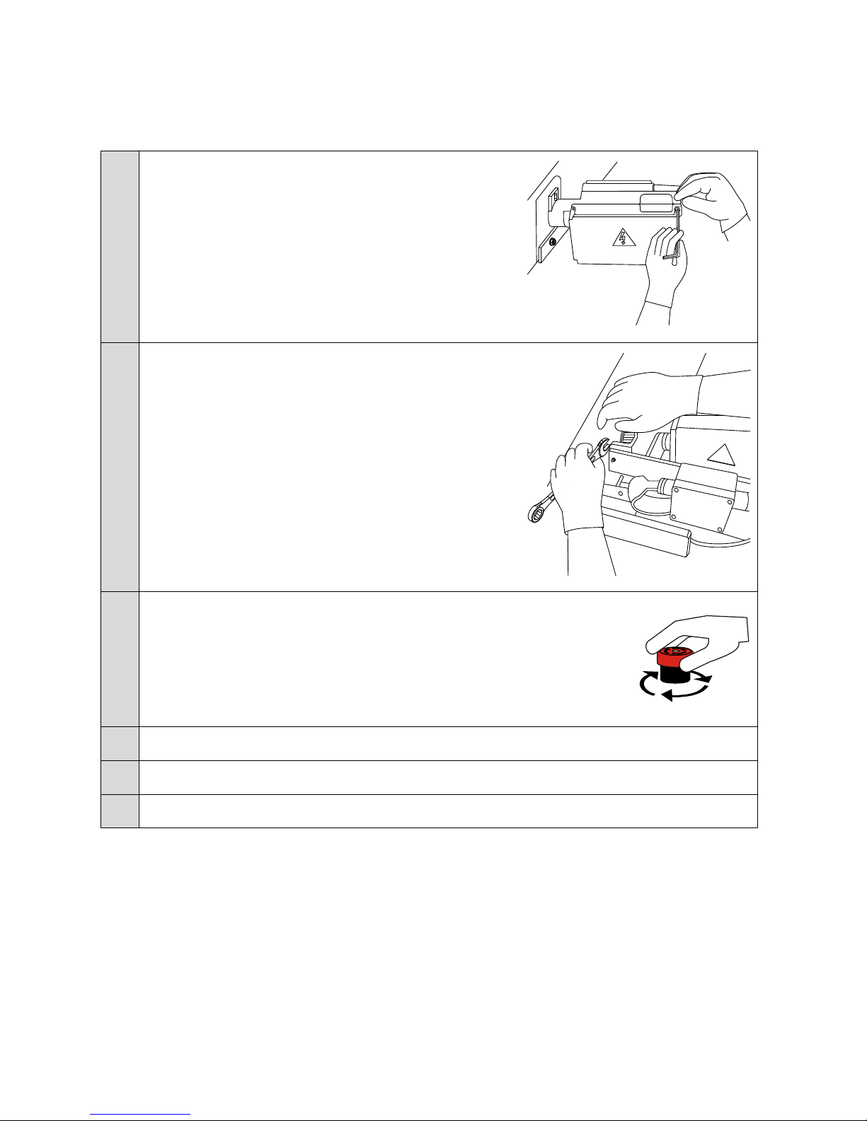
11 Install the motor connection box lid.
12 Install the festoon electric connection box (if installed).
13 Release the main power button up from the pendant or radio controller.
14 Make sure that the trolley move's into correct directions by operating the trolley.
15 Make sure that the traveling speeds are suitable for customer needs by operating the trolley.
16 Make sure that the trolley slow-down ramps are suitable for customer needs by operating the trolley.
R&M Materials Handling, Inc.
4501 Gateway Boulevard
Springfield, Ohio 45502
P.: (937) 328-5100
FAX: (937) 325-5319
16/28 R&M Materials Handling, Inc. reserves the right to alter or amend the above information without notice.

5 COMMISSIONING
Compare the DIP switch settings of the CMX 007 with the following tables and find the correct settings for the
ControlMaster®NXT 003 DIP switches.
5.1 Old inverter parameter settings
Write in the table below the old frequency converter DIP switch settings.
Table 1. CMX 007 parameter settings.
Switch S1 Switch S2 Switch S3 Switch S4
-1 -2 -3 -4 -1 -2 -3 -4 -1 -2 -3 -4 -1 -2 -3 -4
5.2 Driving frequency table selection
The maximum and minimum driving frequencies depend on the nominal frequency of the motor. Use the
following table to determine which table should be used to set
Table 2. Driving Frequency table selection
CMX 007 Switch S4 Maximum Driving
Frequency Table
Minimum Driving
Frequency Table
-2 -3 -4
00035
010
001
10046
110
R&M Materials Handling, Inc.
4501 Gateway Boulevard
Springfield, Ohio 45502
P.: (937) 328-5100
FAX: (937) 325-5319
17/28 R&M Materials Handling, Inc. reserves the right to alter or amend the above information without notice.

5.3 S1 Maximum driving frequency
Set the maximum driving frequency according to the following tables
Table 3. Motor nominal frequency = 100/120 Hz
CMX 007 Switch 1 ControlMaster®NXT 003 Switch 1
-1 -2 -3 -4 -1 -2 -3
0000000
0001111
0010110
0011111
0100100
0101110
0110101
0111
1000001
1001101
1010100
1011010
1100
1101011
1110
1111001
Table 4. Motor nominal frequency = 80 Hz
CMX 007 Switch 1 ControlMaster®NXT 003 Switch 1
-1 -2 -3 -4 -1 -2 -3
0000010
0001011
0010001
0011011
0100110
R&M Materials Handling, Inc.
4501 Gateway Boulevard
Springfield, Ohio 45502
P.: (937) 328-5100
FAX: (937) 325-5319
18/28 R&M Materials Handling, Inc. reserves the right to alter or amend the above information without notice.

CMX 007 Switch 1 ControlMaster®NXT 003 Switch 1
-1 -2 -3 -4 -1 -2 -3
0101011
0110
0111001
1000000
1001111
1010
1011110
1100101
1101100
1110100
1111010
Table 5. Motor nominal frequency = 35 Hz
CMX 007 Switch 1 ControlMaster®NXT 003 Switch 1
-1 -2 -3 -4 -1 -2 -3
0000010
0001000
0010011
0011
0100110
0101011
0110001
0111111
1000010
1001111
1010101
1011100
1100
R&M Materials Handling, Inc.
4501 Gateway Boulevard
Springfield, Ohio 45502
P.: (937) 328-5100
FAX: (937) 325-5319
19/28 R&M Materials Handling, Inc. reserves the right to alter or amend the above information without notice.

CMX 007 Switch 1 ControlMaster®NXT 003 Switch 1
-1 -2 -3 -4 -1 -2 -3
1101010
1110
1111
5.4 S2 Minimum driving frequency
Set the minimum driving frequency according to the following tables:
Table 6. Motor nominal frequency = 100/120 Hz
CMX 007 Switch S2 ControlMaster®NXT 003 Switch S2
-1 -2 -3 -4 -1 -2 -3
0000110
0001000
0010100
0011000
0100111
0101000
0110001
0111101
1000111
1001101
1010010
1011111
1100
1101
1110
1111
R&M Materials Handling, Inc.
4501 Gateway Boulevard
Springfield, Ohio 45502
P.: (937) 328-5100
FAX: (937) 325-5319
20/28 R&M Materials Handling, Inc. reserves the right to alter or amend the above information without notice.
Table of contents
Other R&M Media Converter manuals


