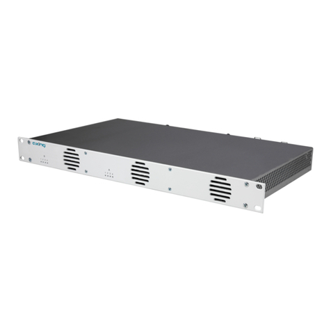
axing HKI 41-34 User manual

HKI 41-34 | HKI 41-35
HKI 81-34 | HKI 81-35
IPTV Encoders
Operation instructions

Operation instructions | HKI 41-34 | HKI 41-35 | HKI 81-34 | HKI 81-35
22017-07-25 | Technical changes, design modifications, errors and misprints are subject to change without prior notice.
Table of contents
1. Product description........................................................................................................................................4
1.1. General..................................................................................................................................................4
1.2. Scope of delivery...................................................................................................................................4
1.3. Connectors on the rear side ..................................................................................................................4
1.4. Typical Application.................................................................................................................................5
2. Mounting and Installation .............................................................................................................................6
3. IP integration.................................................................................................................................................7
3.1. Default IP addresses and logins:............................................................................................................7
3.2. Change the IP addresses into the required IP address space.................................................................7
4. Configuration...............................................................................................................................................10
4.1. Maintenance .......................................................................................................................................10
4.1.1. Network......................................................................................................................................10
4.1.2. Change password .......................................................................................................................10
4.1.3. Upgrade......................................................................................................................................11
4.1.4. Reset...........................................................................................................................................11
4.2. Status of the Encoders.........................................................................................................................11
4.2.1. Stream URL of the encoders ........................................................................................................12
4.2.2. Substream URLs of the encoders.................................................................................................12
4.3. Encoder Settings..................................................................................................................................13
4.3.1. Main stream................................................................................................................................13
4.3.2. Substream1…3...........................................................................................................................14
4.3.3. Audio settings.............................................................................................................................14
4.3.4. Advanced....................................................................................................................................15
4.4. OSD Setting.........................................................................................................................................15
4.4.1. Streaming OSD Setting................................................................................................................15
4.4.2. Substream1…3...........................................................................................................................16
4.4.3. LOGO uploading .........................................................................................................................16
5. Application examples ..................................................................................................................................17
5.1. Preview with the stream with Windows Media Player ........................................................................17
5.2. Multi Local User Application Multicast Way........................................................................................18
5.3. Local Surveillance System Application NVR Connection......................................................................19
5.4. Remote Multi User Application RTMP Connection...............................................................................20
6. Technical specifications ...............................................................................................................................22

2017-07-25 | Technical changes, design modifications, errors and misprints are subject to change without prior notice. 3
Safety instructions:
∂The installation of the device and repair work on the device must be carried out only by a professional
in accordance with the applicable VDE directives. In case of incorrect installation, no liability is
assumed.
∂Never open the device. There are no parts to be maintained by the user inside the device, however,
lethal voltages are present. This also applies to cleaning the device or working on the connections.
∂Use only the mains cable connected to the device or the enclosed power supply unit. Never replace any
parts or make any modifications to the mains cable and the power supply unit. Otherwise, there is a
risk of death.
∂If a replaceable fuse is available, pull out the mains plug before replacing the fuse. Replace defective
fuses only by standardized fuses with the same nominal value.
∂If you intend not to use the device for a longer period of time, we recommend you to completely
disconnect the device from the mains for safety reasons and for saving energy by pulling out the mains
plug.
∂Let the device adjust to the room temperature before commissioning, in particular if condensation is
present on the device, or if it was exposed to large temperature fluctuations.
∂The device must be operated only in moderate climate.
∂The device must be operated only in dry rooms. In damp rooms or outdoors, there is a risk of short-
circuits (attention: risk of fire) or electrical shocks (attention: risk of death).
∂Plan the mounting or installation location such that you can easily reach the mains plug and interrupt
the electric circuit in dangerous situations. Select the mounting or installation location such that
children cannot play near the device and its connections without supervision. The mounting or
installation location must allow a safe installation of all connected cables. Power supply cables and
supply cables must not be damaged or squeezed by any objects.
∂Select a mounting or installation location which meets the requirements of the IP 54 protection class.
Operate the device only on a flat, firm surface and protect it against unintentional movements.
∂Never expose the device to direct solar irradiation and avoid direct vicinity of heat sources (e.g.
heaters, other electrical appliances, fireplace, etc.). It must be always ensured that devices with cooling
elements or ventilation slots are not covered or obstructed. In addition, ensure generous air circulation
around the device. This will prevent possible damage to device and risk of fire due to overheating. It
must be always ensured that cables are not located near heat sources (e.g. heaters, other electrical
appliances, fireplace, etc.).
∂The device is intended for transmission of audio and video signals via LAN cable. Misuse of the device
is expressly prohibited.
∂In particular, the warranty and liability shall be excluded for the consequences of incorrect use, in case
of incorrect modifications or repair work carried out by the customer. Use the device only as described
in the operating instructions and in particular according to the state-of-the-art.
∂The antenna system must be installed and grounded according to the current DIN EN 60728-11
standard.
∂The product complies with the directives and standards for CE labeling.


Operation instructions | HKI 41-34 | HKI 41-35 | HKI 81-34 | HKI 81-35
42017-07-25 | Technical changes, design modifications, errors and misprints are subject to change without prior notice.
1. Product description
1.1. General
HKI 41-34 IPTV Encoder with H.264 coding
4 × HDMI
HKI 41-35 IPTV Encoder with H.265 (HEVC) coding
4 × HDMI
HKI 81-34 IPTV Encoder with H.264 coding
8 × HDMI
HKI 81-35 IPTV Encoder with H.265 (HEVC) coding
8 × HDMI
Common Features:
∂Web-based configuration | Remote maintenance
∂Two redundant power supplies (hot pluggable)
1.2. Field of application:
The devices are only suitable for in-house distribution of HDMI signals over IPTV. If a device is used for other
purposes, no warranty is given!
1.3. Scope of delivery
1 × IPTV Encoder
2 × AC connection cable, power cord
1 × Quick start guide
1.4. Connectors on the rear side
1. AC connectors of the power supplies
2. RJ-45 Ethernet port of the controler
3. RJ-45 Ethernet ports of Encoder 1…4
4. RJ-45 Ethernet ports of Encoder 5…8 (HKI 81-xx)
5. HDMI inputs 1…4
6. HDMI inputs 5…8 (HKI 81-xx)

2017-07-25 | Technical changes, design modifications, errors and misprints are subject to change without prior notice. 5
1.5. Typical Application

Operation instructions | HKI 41-34 | HKI 41-35 | HKI 81-34 | HKI 81-35
62017-07-25 | Technical changes, design modifications, errors and misprints are subject to change without prior notice.
2. Mounting and Installation
Installation may be performed by authorized and skilled electricians only.
Mounting and installation in a 19“rack
The IPTV encoders are mounted in a 19" rack
Mount the unit with four fitting screws (1).
Equipotential bonding
The HKI must be connected to the equipotential bonding according to EN 60728-11.
Power supply
The HKI have two built-in power supply.
Connect both power supplies to an electrical outlet (100 ... 240 VAC / 50 ... 60 Hz).

2017-07-25 | Technical changes, design modifications, errors and misprints are subject to change without prior notice. 7
3. IP integration
The HKI 41-3x includes 1 controler and 4 encoders
The HKI 81-3x includes 1 controler and 8 encoders
All this sub devices have to be in the same IP adress space, to communicate with each other.
3.1. Default IP addresses and logins:
The device is configured via the graphical user interface. To access the user interface, you need a standard
PC/laptop with a network interface, a commercially available network cable and the actual version of the
installed web browser.
IP adress User/password
Control port interface 192.168.0.157 admin/Ramsen8262
Encoder 1 192.168.0.161 admin/admin
Encoder 2 192.168.0.162 admin/admin
Encoder 3 192.168.0.163 admin/admin
Encoder 4 192.168.0.164 admin/admin
Encoder 5 192.168.0.165 admin/admin
Encoder 6 192.168.0.166 admin/admin
Encoder 7 192.168.0.167 admin/admin
Encoder 8 192.168.0.168 admin/admin
3.2. Change the IP addresses into the required IP address space
If the address space of your network does not match that of the HKI (192.168.0.xyz), change the encoder IP
addresses step by step into the required IP address space.
1st Step – change encoders IP addresses in required IP address space.
Configure your computer in to the same IP address space as the default IP addresses of the encoders.
For example: 192.168.0.50
Enter via browser the encoder web interfaces one by one and configure them in to the required address
space.
…
For example:
Encoder 1: 192.168.178.110
Encoder 3: 192.168.178.112
Encoder 5: 192.168.178.114
Encoder 7: 192.168.178.116
Encoder 2: 192.168.178.111
Encoder 4: 192.168.178.113
Encoder 6: 192.168.178.115
Encoder 8: 192.168.178.117

Operation instructions | HKI 41-34 | HKI 41-35 | HKI 81-34 | HKI 81-35
82017-07-25 | Technical changes, design modifications, errors and misprints are subject to change without prior notice.
2nd Step – change the control port IP address in the required IP address space.
Enter via browser the control port web interface (192.168.0.157) and configure it also in to required address
space.
For example: 192.168.178.100 it must be in the same IP-adress space.
Note: After this the connection to the controller is interrupted.
3rd Step – assign the encoder IP addresses in the control port web interface
Configure your computer to the same IP address space as the encoders and the controller.
For example: 192.168.178.50
Enter via browser the web interface of the controller (192.168.178.100).
Choose MAINTENANCE>Network>Encoder IP addresses
Type in the changed encoder IP addresses.
For example:
–Encoder 1: 192.168.178.110
– Encoder 2: 192.168.178.111
– Encoder 3: 192.168.178.112
– Encoder 4: 192.168.178.113
– Encoder 5: 192.168.178.114
– Encoder 6: 192.168.178.115
– Encoder 7: 192.168.178.116
– Encoder 8: 192.168.178.117
Click Apply.

2017-07-25 | Technical changes, design modifications, errors and misprints are subject to change without prior notice. 9
4th Step – connect the devices to a switch
Connect the control port, all encoders and the computer to a switch.
Configure the encoders and system settings as described in chapter 4.

Operation instructions | HKI 41-34 | HKI 41-35 | HKI 81-34 | HKI 81-35
10 2017-07-25 | Technical changes, design modifications, errors and misprints are subject to change without prior notice.
4. Configuration
4.1. Maintenance
4.1.1. Network
Click MAINTENANCE > Network.
Setting all the parameter.
4.1.2. Change password
Click MAINTENANCE > Change password.
Type in the old password.
Type in and confirm the new password.
Click apply.

2017-07-25 | Technical changes, design modifications, errors and misprints are subject to change without prior notice. 11
4.1.3. Upgrade
Click MAINTENANCE > Upgrade.
Browse for the upgrade file on your computer.
Click on Upload.
The file will be uploaded and the flash memory will be upgraded
After the end of the upgrade you can log in to the system again.
4.1.4. Reset
Click MAINTENANCE > Reset.
Click on Reboot.
The controller will reboot
After appr. 1 minute you can log in to the system again.
Click MAINTENANCE > Reset.
Click on HW Reset.
All encoders will be reseted.
4.2. Status of the Encoders
Click ENCODER [#] > Status.
You cab check the following parameters:
∂Running Time
∂CPU Usage in % (If CPU usage always more than 85%, please close some stream.)
∂Memory Usage: in Mb
∂Input Size in px
∂Collected Video Frames
∂Lost Video Frames
∂Audio Samplerate

Operation instructions | HKI 41-34 | HKI 41-35 | HKI 81-34 | HKI 81-35
12 2017-07-25 | Technical changes, design modifications, errors and misprints are subject to change without prior notice.
4.2.1. Stream URL of the encoders
Click ENCODER [#] > Status and scroll down to Main stream.
The URLs of the main streamare shown (see red frame below).
You can enable and chance the URLs (see “Streaming URL” on page 13).
4.2.2. Substream URLs of the encoders
Click ENCODER [#] > Status and scroll down to Substream1,Substream3, or Substream3.
Check the stream URLs (only available, when substreams are enabled, see “Substream1…3” on page 14).

2017-07-25 | Technical changes, design modifications, errors and misprints are subject to change without prior notice. 13
4.3. Encoder Settings
4.3.1. Main stream
Click ENCODER [#] > Encoder > Main stream.
You can just keep the original data without making any changes, or the parameters can be adjusted according
to practical applications.
∂FPS Frames-Per-Second [5-60]
–FPS depends on your output resolution, it can’t exceed the input frame rate. Otherwise the image will
appear to have dropped frames.
–We advice you to set 30 fps normally.
∂GOP Group Of Pictures [5-300]
–We advice you to set 40 GOP.
∂Bitrate (kbit): 1800 [32-32000]
–Live Stream RTMP = 1500-3000kbps
–IPTV 1920*1080p = 4000-12000kbps
∂Encoded size: Choose “Same as input” (=default) or another resolution you prefer.
–If you set the resolution higher then 1280x720, the FPS should be lower than 50.
∂H.264/H.265 Level: Choose “high profile” (=default), “main profile” or “baseline profile”
–Baseline: for mobile devices (smartphone, mp3 player)
–Main: for standard TV
–High: for HDTV
∂Bitrate control: Choose “vbr” (=default) or “cbr”
Streaming URL
You can enable the following streaming protocols by your preference:
∂TS URL
For the transport stream

Operation instructions | HKI 41-34 | HKI 41-35 | HKI 81-34 | HKI 81-35
14 2017-07-25 | Technical changes, design modifications, errors and misprints are subject to change without prior notice.
∂HLS URL
For HTTP Live Streaming (or HLS) which is an adaptive streaming communications protocol to communicate
with iOS and Apple TV devices and Macs running OSX in Snow Leopard or later.
∂FLV URL
For Flash Video which is a container file format used to deliver digital video content.
∂RTSP URL
For the Real Time Streaming Protocol (RTSP) which is a network control protocol designed for use in
entertainment and communications systems to control streaming media servers.
∂RTMP PUBLISH URL
For the Real-Time Messaging Protocol (RTMP) which was initially a proprietary protocol developed by
Macromedia for streaming audio, video and data over the Internet.
∂Multicast IP.
In computer networking, multicast is group communication where information is addressed to a group of
destination computers simultaneously.
After all parameters are set, click Apply.
4.3.2. Substream1…3
If you want to broadcast one programe to different clients, one is for TV clients and another is for moblie phone
clients. You can set high resolution in main stream setting for TV clients and set lower resolution in Substream1
for mobile phone clients to improve the video performance and save bandwidth.
Important: The encoder doesn’t transfer different streams automatically based on different clients , such as high
resolution to TV and lower resolution to mobile phones. By the main stream setting and second stream setting,
you can use only one encoder unit to push dual streaming to different media server node simultaneoursly
instead of two encoders from same video source.
4.3.3. Audio settings
Click ENCODER [#] > Encoder > Audio.
Usually, keep as default, but you can set it as your need.
∂Samplerate:
∂Encoder: Determines which audio codec is used to encode.
–AAC, AAC+, AAC++
–MP3
∂Encoder:
∂Bitrate: 128000 [48000~128000]
∂Analog Vol:
––50 ~ +50
Click Apply, after you have changed one or more parameters.

2017-07-25 | Technical changes, design modifications, errors and misprints are subject to change without prior notice. 15
4.3.4. Advanced
Click ENCODER [#] > Encoder > Advanced.
Click Apply
4.4. OSD Setting
4.4.1. Streaming OSD Setting
Click ENCODER [#] > OSD > Main stream.
You can configure OnScreen Displays in up to 4 different zones for the main stream.
Change the Option Zone you want to parametrize from Disable to Enable.
The Parameters of the zone apear.

Operation instructions | HKI 41-34 | HKI 41-35 | HKI 81-34 | HKI 81-35
16 2017-07-25 | Technical changes, design modifications, errors and misprints are subject to change without prior notice.
Configure the Xand Ycoordinates on the screen.
Type in the Text which should appear on the screen.
Choose a Background color and the Color of the OSD.
Click Apply.
4.4.2. Substream1…3
You can also configure OnScreen Displays in up to 4 different zones for Substream1…3 in the same way as for
the main stream.
4.4.3. LOGO uploading
Click ENCODER [#] > OSD > Logo Upload.
Browse for a grafic file on your computer. Note the requirements.
Click on Upload.

5. Application examples
5.1. Preview with the stream with Windows Media Player
Click ENCODER [#] > Status and scroll down to Main stream.
Copy the TS URL.
Start Windows Media Player.
Press Ctrl + U.
Paste the URL and click OK.
The video will be streamed.

Operation instructions | HKI 41-34 | HKI 41-35 | HKI 81-34 | HKI 81-35
18 2017-07-25 | Technical changes, design modifications, errors and misprints are subject to change without prior notice.
5.2. Multi Local User Application Multicast Way
If many local users need watch the video of same HD encoder at the same time, we suggest using multicast.
Click ENCODER [#] > Encoder > Main stream.
Enable the Multicast IP, then re-power the HD encoder.
Click MAINTENANCE > Reset.
Click on HW Reset.
All encoders are reset.
Click ENCODER [#] > Status and scroll down to Main stream.
There you will find the Multicast URL with its port.
For example copy it into the Windows Media Player.
This address can be visited by many users at the same time.

2017-07-25 | Technical changes, design modifications, errors and misprints are subject to change without prior notice. 19
5.3. Local Surveillance System Application NVR Connection
Confirm if NVR support H.264 decoder. Since using ONVIF, you need enable the "RTSP" function.
Click ENCODER [#] > Encoder > Main stream.
Enable the RTSP URL, then re-power the HD encoder.
If you need the NVR recognize the Audio of HD Encoder, you still need enable the Audio.
Click ENCODER [#] > Encoder > Audio.
Enable the G711A OVER RTPS, then re-power the HD encoder.
Note: If you've finished above setting and still can't open the video , we suggest you dow nload the standard
testing tool to test the ONVIF function of HD Encoder ( Download address http://url.cn/2ESQRcn).

Operation instructions | HKI 41-34 | HKI 41-35 | HKI 81-34 | HKI 81-35
20 2017-07-25 | Technical changes, design modifications, errors and misprints are subject to change without prior notice.
5.4. Remote Multi User Application RTMP Connection
If many users from different location need watch the source of the same HD Encoder, we suggest you use
RTMP. Our product support belowing Free platform: NGINX, RED5 MEDIA SERVER etc. Charged platform:
ADOBE MEDIA SERVER5 and http://mudu.tv/ etc.
Since the current RTMP protocol only support H.264 function, you need set the HD Enco der as H.264, set the
RTMP Address and enable it as below picture. Re-Start the encoder after finishing the setting.
Click ENCODER [#] > Encoder > Main stream.
Note: If you have finished above setting and still can't open the video, please check as below:
Click ENCODER [#] > Status and scroll down to Main stream.
This manual suits for next models
2
Table of contents
Other axing Media Converter manuals

axing
axing HKI 81-34 User manual

axing
axing HKM 40-00 User manual

axing
axing premium-line SVE 5502-09 User manual

axing
axing HKI-135 User manual

axing
axing SAB 5501-10 User manual

axing
axing MIE 3-02 User manual

axing
axing Basic-line AVC 1-00 User manual

axing
axing HKC 1-00 User manual

axing
axing Premium EOC 30-01 User manual

axing
axing HoE 1-00 User manual