R&M ControlMaster Edge User manual

V/T2 W/T3 +/B1 B2
R/
L1
S/
L2
T/
L3
U/T1
RJ45
CAN
GND
STO
CAN
L
CAN
SHLD
CAN
H
CAN
V+
RA RC
Signal LEDs
Drive ready
Drive running
Drive is not ready
CANopen not
connected
CANopen connected
Drive is not powered
Fault, code indicated
by blinking sequence
No active fault
Mains output
U/T1
V/T2
W/T3
3-phase output
B1 B2 Braking resistor
+ - DC bus
Control signals
RJ45 Connection for Bluetooth
STO
+24V Power supply for STO chnl. 1 and 2
S1 STO channel 1
S2 STO channel 2
DCM Digital signal common
CAN
open
CAN GND Ground
CAN L Dominant low
CAN SHLD CAN cable shield (optional)
CAN H Dominant high
CAN V+ Not in use
Relay
output
RA C (common)
RC NO (normally open)
A
General information
R/L1
S/L2
T/L3
3-phase input
PE
Mains input
TDU00xE000
INPUT: 3PH, 380~480VAC, 50/60Hz
OUTPUT1: x.x A , x.x kVA
OUTPUT2: x.x A, x.x kVA
FREQUENCY RANGE: 0~320Hz
VERSION: x.x
EMC LEVEL MODIFIED
OPTION BOARD
Current ratings and switching frequency
TDU 4 kHz 5 kHz 6 kHz 7 kHz 8 kHz 9 kHz 10 kHz 11 kHz 12 kHz 13 kHz 14 kHz 15 kHz
004 3.4 A 3.1 A 2.8 A 2.5 A 2.3 A 2.1 A 1.9 A 1.7 A 1.6 A 1.5 A 1.4 A 1.3 A
009 8.2 A 8.0 A 7.9 A 7.6 A 7.1 A 6.6 A 6.2 A 5.7 A 5.3 A 5.0 A 4.7 A 4.4 A
017 16.5 A 16.0 A 15.5 A 14.7 A 13.7 A 12.9 A 12.0 A 11.2 A 10.6 A 9.9 A 9.2 A 8.7 A
028 28.0 A 27.2 A 26.3 A 24.9 A 23.2 A 21.8 A 20.4 A 19.0 A 17.9 A 16.8 A 15.7 A 14.8 A
045 45.0 A 45.0 A 45.0 A 45.0 A 43.2 A 39.6 A 36.0 A 32.9 A 30.2 A 27.5 A 25.2 A 23.0 A
Rating label
Note: In case of product reclamation, include the following information:
Type, serial number, fault code (if applicable), application (hoist/travel), how problem appears (e.g. fault code
F001 during acceleration).
If any problems or malfunctions occur during commissioning, refer to the troubleshooting section in the
service instructions, to find out the reason. Make sure all problems are solved before you continue operation.
This document and the information contained herein, is the exclusive property of R&M Materials Handling Inc. and represents a non-public, confidential
and proprietary trade secret that may not be reproduced, disclosed to third parties, altered or otherwise employed in any manner whatsoever without the
express written consent of R&M Materials Handling Inc. Copyright 2021 © R&M Materials Handling Inc. All rights reserved.
Frequency converter ControlMaster Edge
QUICK INSTALLATION GUIDE
Disclaimer: Person conducting this work must be appropriately trained and familiar with product range and
related safety instructions. This quick guide only complements original instructions and does not replace them.
Page 1/2 | DOC735078/2 | 26 May 2021
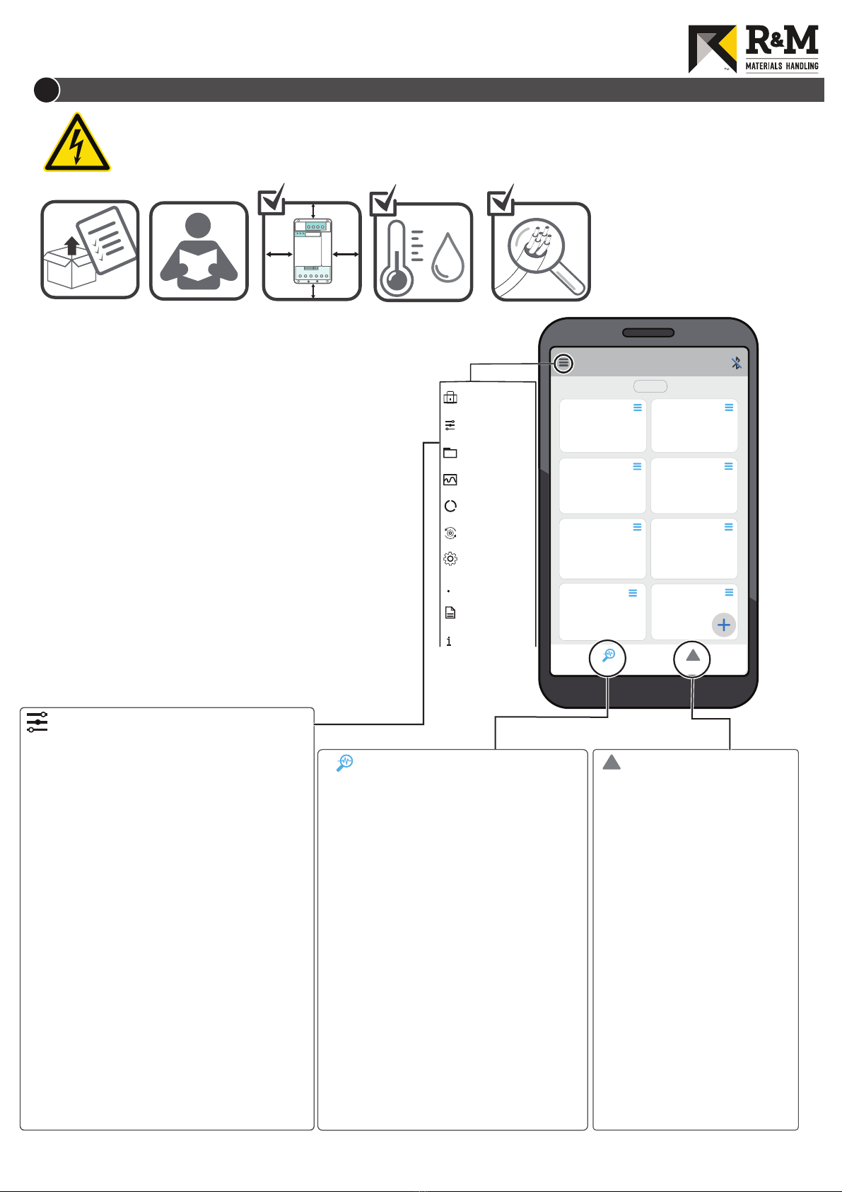
Preparations
1. Check that the delivery corresponds to the order.
2. Read the safety instructions.
3. Check the clearances around device carefully.
4. Check ambient conditions.
5. Check sizes of motor cable, the control wires etc.
6. Check control wirings.
Parameters and commissioning
1. Switch on mains power, release emergency stop
button, and press start pushbutton.
2. To check parameters establish connection between
device and TD DriveTool app.
NOTE: Usually, the parameters are properly set after factory
tests and no adjustments are needed.
• Compact brake motors for traveling (MF06MA, MF06LA)
See the motor parameter values from Service Instruction.
• Other motors for traveling
1. Check parameters 01-00...01-06, and 00-01.
2. Perform automatic tuning with TD Drive Tool
• All motors for lifting
See the motor parameter values from Service Instruction.
NOTE: Use only pre-defined motors with factory tested
parameter values.
Dashboard
Disconnected
RESET
Drive Label
...
Model
...
Output Frequency
...
Hz
Motor Current
...
A
Motor Voltage
V
... ...
IGBT Temperature
oC
Monitor
!
Events
DC Voltage
V
...
Active Warning
...
BInstallation
High voltages inside the device.
Wait at least 5 min after the mains input voltage has been switched off before service actions.
When signal LEDs are on there is dangerous voltage on the DC bus.
When signal LEDs turns off, the DC bus voltage is about 100 V.
Note that there is a dangerous voltage in the braking resistor when DC bus is charged.
RH
°C °F
Device info
Parameters
File manager
Trend
Autotuning
Settings
Support Package
Documentation
About
Datalogger
?
Parameters
!
Events
F001... Over current
F003 Over current
F006 Over current
F007... Overvoltage
F010 Overvoltage
F011... Undervoltage
F014 Undervoltage
F140 Ground fault
F141 Ground fault
F200 CANopen communication
F201 Motor overtemperature
F202 Both directions fault
F203 Ramp supervision
F204 Parameter fault
F205 Parameter fault
Common fault codes
Monitoring values
Output frequency
Motor current
Motor voltage
IGBT
temperature
DC voltage
Freq reference
Freq command
STO input
RO status
DI status
CANopen SW
CANopen CW
Active Warning
Active Fault
Drive Label
Output frequency to the
motor
Output current to the induction
motor
Output voltage to the motor
Internal temperature of IGBT
module
Inverter DC-link voltage
Frequency reference
Frequency command from a
radio or a pendant controller
Safe torque off input status
Status of relay output
Status of digital input
Status word of CANopen
Control word of CANopen
Code of active warning
Code of active fault
Drive label code of the
connected frequency converter
Monitor
00-00 User Role Key 03-06 Motor Rs
00-01 Drive Selection 03-07 Motor Rr
00-02 Accel Time 03-08 Motor Lm
00-03 Decel Time 03-09 Motor Lx
00-04 Min Frequency 03-10 System Inertia
00-05 Max Frequency 03-11 ASR1/2 Switch F
01-00 Motor Nom Volt 03-12 ASR Zero-Speed
01-01 Motor Nom Freq 03-13 ASR1 Low-Speed
01-02 Motor Nom Curr 03-14 ASR2 High-Speed
01-03 No-Load Current 04-00 DI1 Function…
01-04 Motor Cos Phi 04-05 DI6 Function
01-05 Motor Nom Power 05-00 Ramp Stretching
01-06 Motor Nom Speed 05-01 Flux Brake
01-08 Start Current 05-02 Slowdown Mode
02-00 Brake Open Delay 05-03 Brake Chopper
02-01 Start DC Time 06-00 Node ID
02-02 Start Frequency 06-01 CAN Speed
02-03 Load Floating Time 06-02 Control Place
03-00 ESR mode 06-03 Process Data 1…
03-01 ESR Max Freq 06-09 Process Data 7
03-02 Ramp Scale Freq 07-00 Switching Freq
03-03 U/f Zero Freq Volt 08-00 F#1 Fault Record…
03-04 U/f Mid Voltage 08-09 F#10 Fault Record
03-05 U/f Mid Freq
Loremipsum
This document and the information contained herein, is the exclusive property of R&M Materials Handling Inc. and represents a non-public, confidential
and proprietary trade secret that may not be reproduced, disclosed to third parties, altered or otherwise employed in any manner whatsoever without the
express written consent of R&M Materials Handling Inc. Copyright 2021 © R&M Materials Handling Inc. All rights
Page 2/2 | DOC735078/2 | 26 May 2021
Other R&M Media Converter manuals


