Random*Source Serge RING User manual

RANDOM*SOURCE
RANDOMSOURCE.NET 1
Serge RING
SERGE
Ring Modulator 2017
(RING) for Eurorack
The 2017 RING is an improved version of the late Serge
Ring Modulator (R9), designed by Serge himself for
Random*Source in 2017, more than 40 years after the
launch of the Serge Modular system.
To quote the Serge 1983 catalogue:
“Our new RING MODULATOR (RING) is a brand
new design which incorporates greatly improved
specications . Features include the following:
• A VERY CLEAN SOUND down to very low
signal levels (unlike conventional modulators where distortion increases at low levels) .
• 80 dbs OF CARRIER SIGNAL REJECTION.
• INAUDIBLE NOISE OUTPUT .
• NO SQUELCH CIRCUIT IS REQUIRED due to the low noise therefore annoying signal dropouts
and “pumping” effects are totally absent.
• INTERNAL WAVESHAPING OF CARRIER to add to modulation effects.
• The sum total of these design improvements is a Ring Modulator capable of treating the most subtle
acoustical signals, without the coloration typically associated with even the best previously available
ring modulators.
The versatility of the Serge Ring Modulator is enhanced by the added feature of voltage and manual control
of the entire spectrum of modulation possible: from zero modulation (i.e. the original, un-treated input
signal) through amplitude modulation to full ring modulation. This allows many shadings of effect, manual or
automatic with voltage controls. The ability to control the Carrier level manually and through voltage control
allows the output to be level controlled, as well. -Through the use of an internal signal processor for the
Carrier, additional effects can be produced by waveform modication of the carrier signal. When the module
is set to full Ring Modulation from the lower knob or voltage control, the output signal contains the sum and
RANDOM*SOURCE
RANDOMSOURCE.NET 2
Serge RING
difference frequencies of the Signal Input and the Carrier Input. If both signals are pure sine waves (only
one frequency component), the output will be a composite signal consisting two frequency components:
the sum and the difference frequency of the Signal and Carrier. If the Carrier level is increased beyond the
mid-position, then the carrier waveform will become slightly rounded, and new frequency components will
be produced. Each of these new components will also modulate with the Signal input to produce a sum
and difference frequency, and the output signal will become richer in harmonics. This effect. is unique to the
Serge Ring Modulator, and allows another dimension in timbral modication.
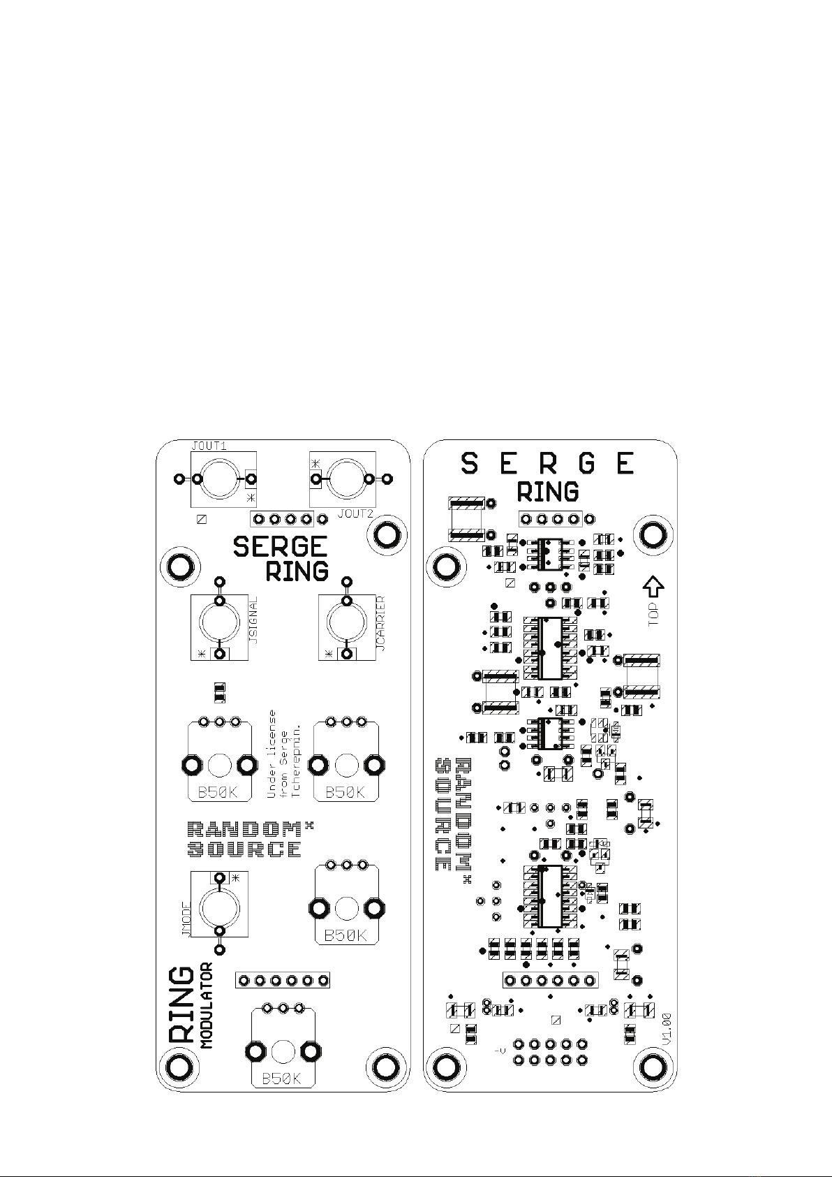
The Random*Source version of the RING for Euro is a licensed and authorized implementation of the new origi-
nal Serge design.
The Random*Source RING kit consists of a front panel and a pcb set with all SMT parts preinstalled. A couple of
through-hole parts (mostly capacitors) have to be installed (1uF caps only if not already installed in SMT!).

RANDOM*SOURCE
RANDOMSOURCE.NET 3
Serge RING
Pleasenote:
• TheRINGrequirescarefulcalibrationforbestresults.A2-channeloscilloscopeishiglyrecommended,
ifnotrequired.
• Themodulerequiresacoupleoflargercapacitors(10uFand4.7uF)andprovidesfootprintsforWIMA
lmcaps.Youshouldbeabletosubstituteothertypes(e.g.bipolarelectrolyticsforaudiouse),however,
theseareuntested.
• If the main pcb already includes 3 large SMT capacitorsin(1uF,blackandsilvercubes)-
mostlikelythisisthecase-,youdonotneedtoinstallany1uFcapacitorsinthrough-hole-i.e.you
can leave the corresponding 1uF through-hole footprints empty.
• Useantistaticprecaution-trytoavoidtouchingtheSMTparts.
• Boardisdesignedtobepoweredbya+/-12VstabilizedPSUonly.(+/-15Visuntested).
BillofMaterials
Capacitors (min. 35V, 5mm lead spacing)
310uF FILM/PET,5mm WIMAMKS2B051001N00JSSD(5%recommended)
14.7uF FILM/PET,5mm WIMAMKS2orsimilar,5%recommended
31uF FILM/PET,5mm WIMAMKS2orsimilar-ONLYIFNOTALREADYINSTALLED
INSMT!
Trimmpots
11k Multiturn e.g.Bourns3296Y-1-102LForVishayT93YB102KT20
1100k Multiturn e.g.Bourns3296Y-1-104LForVishay
1100k Single-Turn e.g.Bourns3362P-1-104LForwhateverts)
Misc
1EuroPower
header
MTA-100powerconnector,Reichelt:WSL10G
5 Thonkiconn
Jacks
3.5mmJackSockets(PJ301M-12)fromThonk
4 Potentionmeter
50k
linear(B50K) Alpha9mmverticalpcbmount
availablefromThonk,Tayda,Mouser...
B100Kshouldalsowork
1Resistor22kor
24k
OPTIONALtoadjustthetaperofthe
MODEpot
CanbeeitherTH(0207)orSMT(0805,1206)
1
1
SILheader6pol
SILheader5polor4pol(checkmarkingsifusing4pol)
pinconnectors,linkingmainpcbtocomponent
pcb-usingprecisionstripsallowstobreakoff
piecesasneeded
4 Spacers+8matchingscrews(M3) 10mmorwhatevermatchestheSILheaders/
connectors

RANDOM*SOURCE
RANDOMSOURCE.NET 4
Serge RING
Building
This is simply a suggestion - you might nd a different workow more practical:
1. Useaside-cuttertoseparatemainpcbandcomponentpcb.
2. Solderthepowerconnectorandotherthrough-holepartstothemainpcb.
3. Addthespacerstothepanelpcbandinstallthepin(SIL)headerssothatthe2pcbsformanicesandwich.Pay
attentiontothedirectionthepcbsarefacing-theSMTpartshavetobeinsidethesandwich.
Itisrecommendedtohavethefemaleheadersonthepanelpcbandthepinsonthemainpcb.
4. Ifyouhavedouble-checkedthatthepositioningiscorrect,solderthepinsconnectingthe2pcbs.
5. Carefullyseperatethe2pcbsagainandmounttheThonkiconnjacksandthepotsontothepanelpcb.Potsshould
sitonthesidefacingthefrontpanel(asmarkedontheboard).Don‘tsoldertheminyet.
6. Carefullymountthepanelpcb(withthepotsetc.inserted)ontothefrontpanel.Youmaythenhavetowiggleeach
potabittogetthepotsthrough.Makesurethethreadsofthepotsgothroughcompletelyandthepotssitrightat
thefrontpanel.Screwthejacksandpotstothepaneltomakesureofthat.
7. Onceeverythingisnicelyinplace,solderthepotsandjacks(whilethefrontpanelisattached).Makesureyou
don‘tspillanysolderontheSMTparts.
8. Mountthemainpcbagainandfastenitusingthespacers.
9. Connectapowercordsupplying+12V,GND,GND,-12Vtothepower-headeronthemainboardanddoublecheck
thedirectionofthepowerheaderbeforeyouturnpoweron.
10. Youshouldbereadytocalibrateandgo:-)
Optional:MODEknobtaperadjustment
You might notice that depending on calibration the spot where the MODE knob reaches exactly the AM position
(before fading to Ring modulation) is slightly before the center of the knob. This does not affect the function in
any way - in particular not the VC MODE behavior) -, however, if that is the case and it bothers you, you can
adjust the knob curve (taper) by soldering a resistor (22k or 24k for a B50K pot should work) between the wiper
of the MODE pot and the GND pin like this:
RANDOM*SOURCE
RANDOMSOURCE.NET 5
Serge RING
Calibration
Feed a 5V pp signal into SIGNAL (e.g. Triangle or SAW from a DSG) and another 5V pp signal into CARRIER.
The SIGNAL should be in the audio range, but not too fast, as waveforms may change otherwise, 1-2 kHz
should do it. The signal into CARRIER should be slower, for instance around 50 Hz. Turn both attenuators fully
CW. Use a scope to see both the CARRIER signal as well as the OUTPUT (using either output - they are
identical).
(A) Set MODE fully CW and adjust the three trimmers so that theOUTPUThasnoDCoffsetandshowsanice
symmetrylikethis:
You will notice that this is an iterative process - the top trimmer controls the vertical (DC) offset, however, the
other two trimmers kind of act like a joystick, shifting the balance of the output waveform. Don’t expect to get
a perfect result at once! Also, vary the frequencies of the incoming signals to see if there are any changes in the
waveforms of the incoming signals. The bottom trimmer kind of tilts / rotates the waveform - this is where you
should (carefully start). You will most likely have to revisit the DC offset trimmer after changing the others. Try a
different waveform for CARRIER, too. Here’s the SINE OUT of a Serge NTO:

RANDOM*SOURCE
RANDOMSOURCE.NET 6
Serge RING
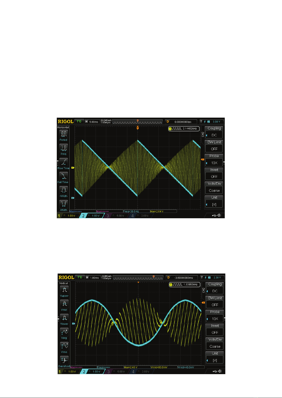
(B) Turn the MODE knob to center position (AM). When feeding a was wave into the CARRIER, you should be
able to get a beautiful amplitude modulated OUTPUT like this:
Beware that the singal and carrier level going in will affect the symmetry - a DSG mk2 will show an increase of
amplitude when either Rise or Fall is very steep (towards the ends of the knob ranges) - the module is designed
to work with 0-5V / 5V pp levels going in (i.e. standard Serge signal levels) - thanks to the input attenuators any
“hotter” signal levels should be no problem, however, for calibration it is recommended to use a 5V signal and
have th attenuators opened all the way.
At minimum position (CCW), the module has no effect, letting only the SIGNAL pass through. Moving towards
center position it seamlessly blends to amplitude modulation (AM) where it starts to move towards ring
modulation - full CW will deliver full ring modultion as shown in (A).
TipsandTricks
• Traditionallysinewavesareconsideredbestforringmodulation(astheyhavenoharmonicovertones),
however,trysaworsquare/pulsewavesforinteresting,richresults.
• ADSGmk2isagreatpartnerasitallowstogouptoabout12kHzandprovidesvariousoutputs.Try
combiningtheRINGwithFMontheDSGforamazingeffects.
• YoucanfeedanegativevoltageasModeCV,i.e.bipolarsignalsworkaswell-turntheMODEknobup
forthisasthenegativeCVactsasifyouturnedtheMODEknobdown.
• Tryrunningoneoftheinputsignalsthroughawaveshaper(e.g.SergeVCMorTWS)forinterestingef-
fects,especiallyifyoufeedtwosignalsthatarealmostidenticalinfrequency-thatcangeneratevery
slow,complexmorphingsounds.
Last edited on 18. March 2018, 10:20 PM
SERGE Modular by Random*Source. Module and circuit under license from Serge Tcherepnin. All rights reserved.
Table of contents
Other Random*Source Music Equipment manuals


