PRODUCT DESCRIPTION
A-Range
A-Range
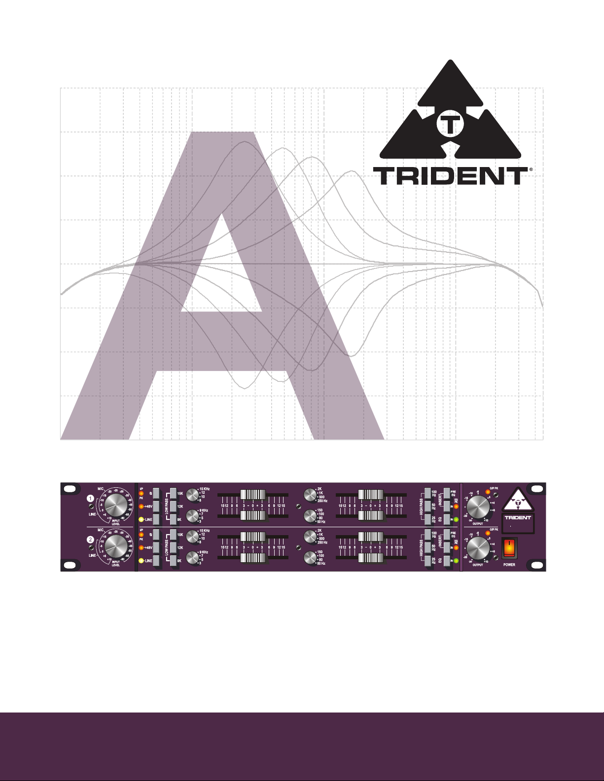
both microphone and
line inputs) and an output level control with peak signal indication.
All inputs and outputs are balanced so that maximum signal integrity and high output levels are
assured with minimum distortion.
A useful additional facility when using it as a stand-alone unit is the inclusion of LED peak level
indicators at key points in the signal chain. These are located: directly after the input amplifiers
(microphone and line), after the equaliser section and after the main output amplifier. This ensures
that the signal is accurately monitored and matched at all stages in the signal chain.
A-Range
discrete transistor microphone and line input preamplifiers or the unique and versatile equaliser
sections.
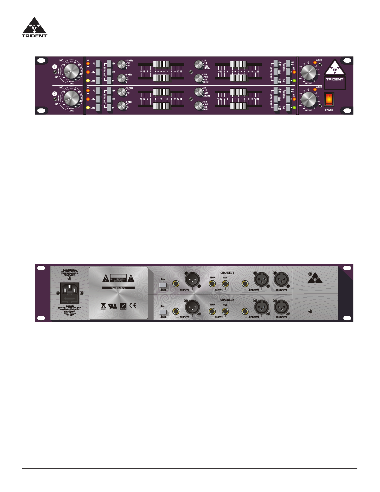
CONNECTING THE UNIT
The rear panel of the unit provides both XLR and ¼" jack inputs for the line input and output of each
channel while a separate XLR is provided for the microphone input. The insert sends and returns are
¼" jacks. The XLR connectors use the standard industry convention of pin 1 ground, pin 2 positive
and pin 3 negative. The jacks are tip-positive, ring-negative and sleeve ground. For unbalanced use,
connect the ring to the sleeve.
The is a 2-channel rack-mountable version of the legendary Trident 'A' Range console.
Comprising two independent channels, each with a microphone/line amplifier and four band
equaliser, it is designed to process incoming signals from a microphone or line level instrument and
output to a recording device, such as a digital audio workstation or analog multi-track tape recorder.
Mains powered, with 48 volt phantom power independently switchable for the two channels, the
operates as a complete stand-alone unit.
In keeping with its mixing console heritage, each 'channel strip' of this rack unit features insert points
(switchable pre/post EQ and with bypass), phase reverse (which operates on
The rack will add its own signature to any programme material, whether using just the
®
®
®
OO
A RANGE
CAUTION
RISQUE DE CHOC ELECTRIQUE
NE PAS OUVRIR
ENSURE MAINS VOLTAGE AND FUSE RATINGS
ARE CORRECT BEFORE CONNECTING MAINS POWER.
THIS APPARATUS MUST BE EARTHED BY THE POWER CORD.
NO USER SERVICEABLE PARTS -
REFER SERVICING TO QUALIFIED PERSONNEL.
A RANGE
Distributed Exclusively by PMI Audio Group
Gardena, California 90247 USA
www.trident-audio.com
Designed in England
Assembled in the USA
to Trident Audio’s strict specifications
DUAL CHANNEL DISCRETE
MIC AMPLIFIER AND EQUALISER
TRIDENT
TRIDENT AUDIO DEVELOPMENTS
TRIDENT SERIES
®
®
®
EN55103
EN60065
PRODUCT DESCRIPTION
A-Range
A-Range
both microphone and
line inputs) and an output level control with peak signal indication.
All inputs and outputs are balanced so that maximum signal integrity and high output levels are
assured with minimum distortion.
A useful additional facility when using it as a stand-alone unit is the inclusion of LED peak level
indicators at key points in the signal chain. These are located: directly after the input amplifiers
(microphone and line), after the equaliser section and after the main output amplifier. This ensures
that the signal is accurately monitored and matched at all stages in the signal chain.
A-Range
discrete transistor microphone and line input preamplifiers or the unique and versatile equaliser
sections.
CONNECTING THE UNIT
The rear panel of the unit provides both XLR and ¼" jack inputs for the line input and output of each
channel while a separate XLR is provided for the microphone input. The insert sends and returns are
¼" jacks. The XLR connectors use the standard industry convention of pin 1 ground, pin 2 positive
and pin 3 negative. The jacks are tip-positive, ring-negative and sleeve ground. For unbalanced use,
connect the ring to the sleeve.
The is a 2-channel rack-mountable version of the legendary Trident 'A' Range console.
Comprising two independent channels, each with a microphone/line amplifier and four band
equaliser, it is designed to process incoming signals from a microphone or line level instrument and
output to a recording device, such as a digital audio workstation or analog multi-track tape recorder.
Mains powered, with 48 volt phantom power independently switchable for the two channels, the
operates as a complete stand-alone unit.
In keeping with its mixing console heritage, each 'channel strip' of this rack unit features insert points
(switchable pre/post EQ and with bypass), phase reverse (which operates on
The rack will add its own signature to any programme material, whether using just the
®
®
®
O
A RANGE
CAUTION
RISQUE DE CHOC ELECTRIQUE
NE PAS OUVRIR
ENSURE MAINS VOLTAGE AND FUSE RATINGS
ARE CORRECT BEFORE CONNECTING MAINS POWER.
THIS APPARATUS MUST BE EARTHED BY THE POWER CORD.
NO USER SERVICEABLE PARTS -
REFER SERVICING TO QUALIFIED PERSONNEL.
A RANGE
Distributed Exclusively by PMI Audio Group
Gardena, California 90247 USA
www.trident-audio.com
Designed in England
Assembled in the USA
to Trident Audio’s strict specifications
DUAL CHANNEL DISCRETE
MIC AMPLIFIER AND EQUALISER
TRIDENT
TRIDENT AUDIO DEVELOPMENTS
TRIDENT SERIES
®
®
®
EN55103
EN60065
7
Trident A-RANGE Owners Manual3
Trident A-RANGE Product Description
The A-Range® is a 2-channel rack-mountable version of the legendary Trident ‘A’ Range console. Comprising two
independent channels, each with a microphone/line amplifier and four band equaliser, it is designed to process
incoming signals from a microphone or line level instrument and output to a recording device, such as a digital au-
dio workstation or analog multi-track tape recorder. Mains powered, with 48 volt phantom power independently
switchable for the two channels, the A-Range® operates as a complete stand-alone unit.
In keeping with its mixing console heritage, each ‘channel strip’ of this rack unit features insert points (switchable
pre/post EQ and with bypass), phase reverse (which operates on both microphone and line inputs) and an output
level control with peak signal indication. All inputs and outputs are balanced so that maximum signal integrity and
high output levels are assured with minimum distortion.
A useful additional facility when using it as a stand-alone unit is the inclusion of LED peak level indicators at key
points in the signal chain. These are located: directly after the input amplifiers (microphone and line), after the
equaliser section and after the main output amplifier. This ensures that the signal is accurately monitored and
matched at all stages in the signal chain.
The A-Range® rack will add its own signature to any programme material, whether using just the discrete transis-
tor microphone and line input preamplifiers or the unique and versatile equaliser sections.
Connecting The Unit
The rear panel of the unit provides both XLR and 1/4”” jack inputs for the line input and output of each channel
while a separate XLR is provided for the microphone input. The insert sends and returns are 1/4” jacks. The XLR
connectors use the standard industry convention of pin 1 ground, pin 2 positive and pin 3 negative. The jacks are
tip-positive, ring-negative and sleeve ground. For unbalanced use, connect the ring to the sleeve.
When connecting a microphone, set the ‘Input Level’ control for each channel to minimum, with the phantom
power +48V switch o (LED extinguished). The microphone input is designed to accept the signal from low im-
pedance, balanced microphones of either dynamic, ribbon or condenser types. The line input is designed to ac-
cept balanced or unbalanced, line level audio signals. Mic or Line input is selected via the front panel ‘Line’ switch
(LED lights for ‘Line’). The outputs from each channel are low impedance and designed to operate with long cable
runs without signal degradation. A standard IEC mains inlet is provided for AC mains power. Operating voltage of
either 120 or 240 volts is selectable by rotating the fuse holder incorporated into the mains inlet socket.