Random*Source SERGE SSG User manual

RANDOM*SOURCE
RANDOMSOURCE.NET 1
Serge SSG
SERGE
Smooth & Stepped
Generator (SSG)
The Serge Smooth & Stepped Generator (SSG) is an essential part of the Serge system. According to the 1979
catalogue, “it is a complex multi-functional module which can be patch programmed to provide various slew
and sample functions.
The Smooth section will place a postitve and
negative slew on input voltage transitions for lag
effects, voltage controlled portamento and for
low frequency lter applications.” In Cycle-mode
(cycle jack patched to the input), the Smooth
side “will oscillate yielding a voltage controlled
traiangle wave LFO. A high level into the HOLD
input will enable the Smooth Function to be used
as a track-and-hold circuit with voltage controlled
slew rate.
The Stepped funtion can be used as a sample-
and-hold with voltage controlled slew rate
limiting. In Cycle mode, a pulse applied to the
Sample input will generate complex staircase
waveforms for control voltage applications and
for use as audio signals.
The Coupler is an internal comparator which compares the output levels of the Smooth and the Stepped Gen-
erators. This output is useful for generating complex control voltages or random voltages.
The Random*Source version of the Smooth & Stepped Generator is a licensed and authorized adaption of the
original Serge design that provides an increased audio range of the Smooth Generator and a bipolar (“hot”) Cou-
pler output in addition to the regular (unipolar) Coupler output.
The Random*Source SSG + Random Source (RS) 4x4 kit consists of a front panel, a component pcb serving as
an interface to the front panel as well as two main pcbs (one for the SSG, one for the RS), each of which already
contains most of the parts in surface-mount technology (SMT). This document only describes the SSG side.

RANDOM*SOURCE
RANDOMSOURCE.NET 2
Serge SSG
Random Source and SSG essentially use the same main pcb, however, the SSG version only contains parts in
the upper area whils the RS requires the fully installed pcb (i.e. also the lower area containing the Serge Noise
Source and Sample&Hold).
Please note:
• TheRandom*SourceSSGpcbisavailableindifferentcongurations-for the “normal” SSG,
the pcb version that only contains the upper parts is sufcient(i.e.nottheonesgreyed-
outinthepictureabove).
• Orientationofthemainpcb:power header is at the bottom(whenlookingatthemoduleup-
right,e.g.inarack).
• Use antistatic precautionwhenhandlingthepcb-don’ttouchthesmallSMDpartsandICs
withyourhands.
• Onlythesepartshavetobesolderedin:trimpots,220nFFilmcapacitor,pinstripestoconnectthe
mainpcbtothecomponentpcb,MTApowerheader(seepictureabove).
• LED:Toset/controlLEDbrightness,installeithertrimpots(“LED”)orresistors(e.g.2k)onthe
componentpcb-donotinstallboth!Use low current (max 2mA) LEDs-resistoronboard),
whenusingblueorwhitethisislessrelevant.
• Thecomponentpcbcontainssomepotentiometerfootprintsthatallowyoutochosethedirection
inwhichthepotentiometerworks.Usethe“NORMAL”orientation(asmarkedonthepcb)unless
youhaveagoodreasonnotto.

RANDOM*SOURCE
RANDOMSOURCE.NET 3
Serge SSG
Bill of Materials
Trimmers
2 100k Rate Stepped,
Rate Smooth
Trimpot (Bourns 3362P, Vishay T73YP104KT20 or anything
that matches the footprint). See calibration info below.
2 2K or more LED brightness (instead of
RLED resistors)
Trimpot (Bourns 3362P or Vishay T73YP202KT20 or any-
thing that matches the footprint) to adjust the LED bright-
ness. Pick value depending on LED (see text).
Resistors
2 (2k*) RLED* Pick according to LEDs and desired brightness if not using
trimpots.
Capacitors
1 220n Film (Wima MKS-2-5 or similar) or C0G
Misc
2 LED 5mm low current (max) 2 mA pick color to suit LED lens.
2 LED lens 5mm VCC, Mouser 593-3000R (red),
593-3000A (amber) ...
1
1
1
SIL header 4pol
SIL header 6pol
SIL header 10pol
pin connectors/headers, linking main pcb to component
pcb - using precision strips allows to break off pieces as
needed
5 Banana Jacks 2x CYCLE, HOLD, SAMPLE,
(normal) COUPLER (red)
Emerson-Johnson
Mouser: 530-108-0902-1 (red) or Thonk
2 Banana Jacks 2x IN, (“hot”) COUPLER
(black)
Emerson-Johnson
Thonk / Mouser: 530-108-0903-1 (black)
4 Banana Jacks 2x CV, 2x OUT (blue or white) Emerson-Johnson
Thonk / Mouser: 530-108-0910-1 (blue),
530-108-0901-1 (white)
4 Potentionmeter
50k
linear (B50K) Alpha 9mm vertical pcb mount
available from Thonk, Tayda
1 MTA-156 MTA-156 power connector

RANDOM*SOURCE
RANDOMSOURCE.NET 4
Serge SSG
Building
This is simply a suggestion - you might nd a different workow more practical:
1. MounttheBananajacks,theLEDlensandtheswitchontothefrontpanel.Ifyouuseretention
ringsfortheLEDlenses,attachtheringtothelens.
2. Mountthepotsontothecomponentpcb.Potsshouldsitonthesidemarkedonthepcb-thisside
facesthefrontpanel.Don‘tsoldertheminyet.SticktheLEDsintothecomponentpcb-thelong
legmustbeatthe+side.
3. Carefullymountcomponentpcb(withthepotsandLEDsinserted)ontothefrontpanel.Firstslide
/pushtheLEDsintotheLEDlens-alltheway,thismaytakeabitofforce.Youmaythenhaveto
wiggleeachpotabittogetthepotsthrough.Makesurethethreadsofthepotsgothroughcom-
pletelyandthepotssitrightatthefrontpanel.Youcanevenscrewthepotstothepaneltomake
sureofthat,butyouhavetounscrewthemagainlater(forStep5).
4. Onceeverythingisnicelyinplace,especiallytheLEDssittinginside(andnotontop)oftheLED
lenses,soldertheLEDsandthepotsontothecomponentpcb(whilethefrontpanelisattached).
DONOTSOLDERTHEBANANAJACKSYET!
5. Solderthethrough-holepartsontothemainboard.
6. MainpcbandcomponentpcbaretobeconnectedthroughprecisionDIPsocketandpins.Itis
recommendedtousethepinsonthemainpcb(facingdown,solderedfromabove)andthepin
socketsonthecomponentpcb(standingup,solderedfromthefrontpanelside).Breakorcutoff
thepiecesyouneedandstickthemtogethersothatmainpcbandcomponentpcbformanice
sandwich(don‘tsolderyet).Checkthatyoudidn‘tleaveoutanypins/holesandthatthesockets
areallonthesameside(componentpcb).Solderallthepinsinwhilekeepingthesandwich
together-thisavoidsanymisalignments.
7. Carefullyseparatethesandwich-ifyouusedprecisionsockets,thismaynottotooeasy-they
sticktogethernicely(givingagoodconnection).
8. Mountthecomponentpcbontothefrontpanelagainandscrewonthepotsfromthefrontside.
9. Makesureeverythingisinplace.

RANDOM*SOURCE
RANDOMSOURCE.NET 5
Serge SSG
10. Solderthebananajacksin.Youcaneithersolderthemdirectlytothesurroundingvias(ring
round)or-whichmakesremovingeasiershouldyoueverneedtodothat-byinsertingastiff
(bare)wireintothelittlehole(via)andsolderthatwiretothetopofthebananajack:
11. Attachanyscrews/spacersifdesiredandmountthemainpcbontothecomponentpcb.
12. Connectapowercordsupplying+12V,GND,GND,-12VtotheMTA-headeronthemainboardand
youshouldbereadytogo:-)
Calibration
There’s one trimmer for each side that - among other things - determins the range covered by the RATE potenti-
ometers. The most efcient way for the Smooth Generator seems to be:
1. TurnonCyclemodebypatchingCYCLEintoINandturnuptheRATEpottomaximum.
2. Trytoincreasethespeed/frequencyofthecycleusingthetrimpot.Fromacertainpointon,the
trimmerwillnothaveanyeffectonthespeed/frequencyanymore.Turnbackthetrimmertond
thespotwhereitisabouttoslowdownthecycle.Keepthetrimmerrightatthepointwherethe
speedisstillmaximum.
For the Stepped Generator the procedure is basically the same, but you have to run a (high frequency) pulse
wave into the SAMPLE jack (the Stepped side doen’t cycle without a pulse into SAMPLE). Observe the output
(using an oscilloscope if possible). As on the Smooth side, adjust the trimmer for the spot where the speed is
still as fast as possible. If you turn back the RATE pots to minimum, the CYCLE should now be very slow on
each side.
If you installed trimpots for LED brightness on the component pcb, adjust them according to taste.

RANDOM*SOURCE
RANDOMSOURCE.NET 6
Serge SSG
First Steps
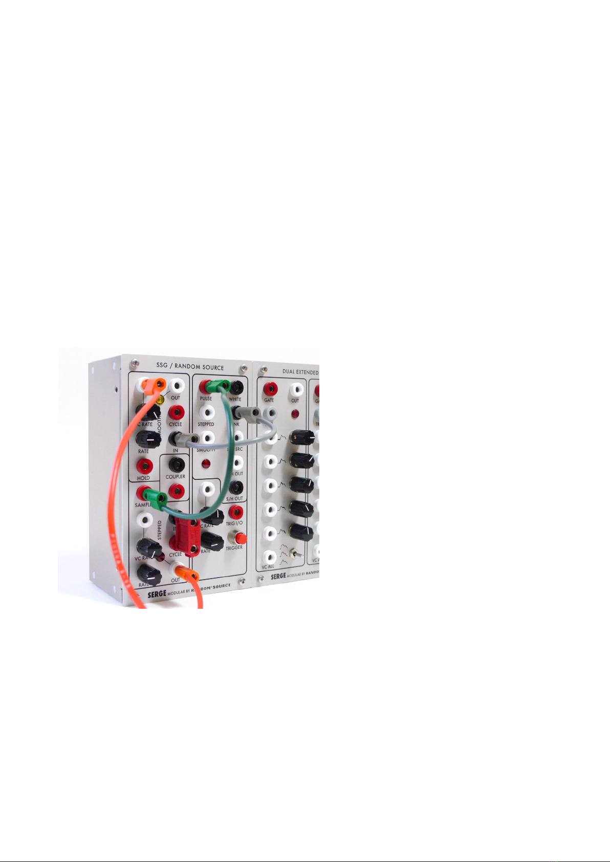
The SSG is a complex, highly versatile module which allows for a wide range of uses and abuses both in the
audio and CV range, so it may require some time and experimenting to familiarize oneself with it - don’t expect
the module to reveal its secrets and power in a few minutes after you rst power it up. Here are some very basic
ideas to start with:
1. PatchtheCYCLEjackintotheINoftheSmoothsection-theSmoothsidethenproducesatri-
anglewavefromabout0Vto4to5V(dependingonfrequncy),theLEDshouldindicatethat.The
Ratepotdeterminesthefrequencyofthecycle/output-therangeisverywide,goingfrombelow
1Hz(dependingoncalibrationabove,possiblyfarbelow1Hz)toappr.4kHz.TheCycle jack
providesacorrespondingPulsewaveoutput.
2. PatchtheCYCLEjackintotheINoftheSteppedsideaswell.UnliketheSmoothside,theStep-
pedsidewillnotgenerateanoutputinCyclemode(=LEDstaysdark)unlessaPulsewaveisfed
intotheSamplejack.Patchapulsewave-e.g.theCycleoutputoftheSmoothside-intothe
Samplejacktobringthesteppedsidetolife.Thesteppedsideisessentiallyasample-and-hold
circuit,theRateknobdetermineshowlongeachstepisattheSteppedoutput.Changingthe
frequencyofthepulsegoingintotheSampleinputand/orchangingtheRateaffectstheoutput.
3. TheSmoothSidecanbeusedasaLowpass lter.Feedanaudiosignal(e.g.asaworpulse
wavefromanoscillator)intotheIN jack(whilenotcycling)andlistentothesignalcomingfrom
theSmooth outwhileyouturntheRate knob.Atmaxiumposition(fullCW)thesignalshould
soundprettymuchunltered,turningtheRatedown(counterclockwise)theharmonicsgetltered
/smoothedout,atminimumpositionthesignalwilldisappearaltogether.
4. UsingtheVCinputjackinthesamesetupasbefore,thisltereffectcanbeusedtoachievethe
effectofaLowpass Gate / VCA.SendanCVenvelope(e.g.fromaDUSGoranExtendedADSR
module)intotheVCjackandturntheVCknobsufcientlyhigh.TunetheRatepottoapositionso
thattheoutputissilentwhennoCVisappliedbutclearlyaudiblewhentheenvelopeishigh.This
causesaVCAeffect,buttheenvelopenotonlydeterminestheamplitude,butalsotheamountof
lteringapplied(likealowpassgate).
Power Consumption
Power consumption: <=30mA @ +12V and <=30mA @ -12V
(Version 23 December 2015)
SERGE Modular by Random*Source. Module and circuit under license from Serge Tcherepnin. All rights reserved.
Table of contents
Other Random*Source Music Equipment manuals