manuals.online logo
Brands
  1. Home
  2. •
  3. Brands
  4. •
  5. Technics
  6. •
  7. Music Equipment
  8. •
  9. Technics ST-GT1000 User manual

Technics ST-GT1000 User manual

Other Technics Music Equipment manuals

Technics SX-GN6 User manual

Technics

Technics SX-GN6 User manual

Technics SM-AC1200 User manual

Technics

Technics SM-AC1200 User manual

Technics Midi SX-EX70 User manual

Technics

Technics Midi SX-EX70 User manual

Technics SX-AX3 User manual

Technics

Technics SX-AX3 User manual

Technics SX-PX201 User manual

Technics

Technics SX-PX201 User manual

Technics SX-PR604 User manual

Technics

Technics SX-PR604 User manual

Technics SA-C600 Installation and service instructions

Technics

Technics SA-C600 Installation and service instructions

Technics ST-G30 Reference manual

Technics

Technics ST-G30 Reference manual

Technics RS-X120 User manual

Technics

Technics RS-X120 User manual

Technics OTTAVA f SC-C65 Installation and service instructions

Technics

Technics OTTAVA f SC-C65 Installation and service instructions

Technics SX-PR53 User manual

Technics

Technics SX-PR53 User manual

Technics ST-C700 User manual

Technics

Technics ST-C700 User manual

Popular Music Equipment manuals by other brands

Aguilar CHORUSAURUS user guide

Aguilar

Aguilar CHORUSAURUS user guide

Fishman NEO-D user guide

Fishman

Fishman NEO-D user guide

HEXDEVICES Tama 12 user manual

HEXDEVICES

HEXDEVICES Tama 12 user manual

Mesa/Boogie Flux-drive owner's manual

Mesa/Boogie

Mesa/Boogie Flux-drive owner's manual

DOLFINOS The CARBON Edition user manual

DOLFINOS

DOLFINOS The CARBON Edition user manual

DAPAudio IPS-PT user guide

DAPAudio

DAPAudio IPS-PT user guide

Dynacord DPM 8016 owner's manual

Dynacord

Dynacord DPM 8016 owner's manual

Moen GEC8 Live owner's manual

Moen

Moen GEC8 Live owner's manual

Fender 1 brochure

Fender

Fender 1 brochure

Yamaha MLC-16 operating manual

Yamaha

Yamaha MLC-16 operating manual

Sonuscore TIME TEXTURES manual

Sonuscore

Sonuscore TIME TEXTURES manual

flight of harmony V'Amp user guide

flight of harmony

flight of harmony V'Amp user guide

NANO PERFORMANCE MIXER quick guide

NANO

NANO PERFORMANCE MIXER quick guide

BHI NEIM 1031 MKII user guide

BHI

BHI NEIM 1031 MKII user guide

Befaco KICKALL user manual

Befaco

Befaco KICKALL user manual

Paia 9720 Assembly and using manual

Paia

Paia 9720 Assembly and using manual

limex ALPIN MASTER 128 user manual

limex

limex ALPIN MASTER 128 user manual

nord Electro 3 user manual

nord

nord Electro 3 user manual

manuals.online logo
manuals.online logoBrands
  • About & Mission
  • Contact us
  • Privacy Policy
  • Terms and Conditions

Copyright 2025 Manuals.Online. All Rights Reserved.

Service Manual
TOP NEXT
AD9908187C2
DAB Tuner
- ST-GT1000
Colour
(K)..........Black Type
Areas
(EB).......Great Britain.
(EG).......Europe.
1999 Matsushita Electric Industrial Co., Ltd. All rights reserved. Unauthorized copying and
distribution is a violation of law.
1
TOP NEXT
2
1 Before Repair
TOP PREVIOUS NEXT
1. Turn off the power supply. Using a 10 , 10 W resistor, connect both ends of power supply
capacitors (C822, C833) in order to discharge the voltage.
2. Before turning the power supplyon, after completion of repair, slowlyapplythe primaryvoltage by
using a power supplyvoltage controller to make sure that the consumed current at 50 Hz in NO
SIGNAL mode should be shown below with respectto supplyvoltage 230/240 V.
Powersupplyvoltage AC230V,50Hz AC240V,50Hz
Consumedcurrent 20-60mA 20-60mA
TOP PREVIOUS NEXT
1
2 Protection Circuitry
TOP PREVIOUS NEXT
The protection circuitrymayhave operated if either of the following conditions is noticed:
- No sound is heard when the power is switched ON.
- Sound stops during a performance.
The functions of this circuitryis to prevent circuitrydamage if, for example, the positive and negative
speaker connection wires are shorted, or if speaker systems with an impedance less than the indicated
rated impedance of this unit are used.
If this occurs, follow the procedure outlined bellow:
1. Switch OFF the power.
2. Determine the cause of the problem and correct it.
3. Switch ON the power once again.
Note:
When the protection circuitryfunctions, the unit will not operate unless the power is first switched OFF
and ON again.
TOP PREVIOUS NEXT
1
3 Accessories
TOP PREVIOUS NEXT
- AC mains lead
(EB) area : (RJA0053-2X)......................1 pc.
(EG) area : (RJA0019-2K).................... 1 pc.
- AM loop antenna
(RSA0022-J)..........................................1 pc.
- FM indoor antenna
(RSA0007).............................................1 pc.
- DAB Tantenna
(RSA0028).............................................1 pc.
- Stereo phono cable
(RJL4P004B08)......................................1 pc.
- DAB antenna plug adaptor
(RFE0014).............................................1 pc.
1
- FM antenna plug adaptor for (EB) area only
(SJP9009)..............................................1 pc.
- Remote control transmitter
(RAK-STA23WH)....................................1 pc.
- Batteries
(R6/LR6, AA, UM-3).................................2 pcs.
Note: These are available on sales route.
TOP PREVIOUS NEXT
2
4 Caution for AC Mains Lead
TOP PREVIOUS NEXT
TOP PREVIOUS NEXT
1
77
77
7Front Panel Controls
FREQENCY
SERVICE
FM
123
456
7890
AM
DELETE
DISPLAY
MENU
DATA
ANNOUNCEMENT
10
DAB
TUNING MODE
SERVICE
FREQENCY
MEMORY
ENTER
PTY
SEARCH
PRESET
PRIMALY/
SECONDARY
FM AM
ANNOUNCEMENT SECONDARY SERVICE
DATA RDS
STEREO
AUTO TUNING
DAB
PTY SELECT (PUSH-SEARCH)
PRESET
SERVICE- FREQUENCY
PUSH OPEN
ANNOUNCEMENT
CANCEL
MENU ENTER DISPLAY
MEMORY
DELETE MEMORY
AUTO MEMORY
PRIMARY/
SECONDARY
DATA
TUNING
ATUO/MANUAL
2
1345678
9
10 11 12 13 14 15 16
17 18
19
20
18
17
10
5
9
16
3
8
13
14
6
15
11
Main unit
1Unit on/off button ( /I) and
remote standby indicator ( )
Use this button to turn the unit on and off.
(off): The unit is in standby mode.
(on): The unit is on. The unit can be turned on and off with
the remote control. When the unit is turned off with the
remote control it is in remote standby and the indicator
lights.
The unit is still using a small amount of power in the standby and
remote standby conditions. Standby uses less power.
2Remote control signal sensor
3Band select buttons (DAB, FM, AM)
4Reception and setting indicators
(ANNOUNCEMENT, SECONDARY SERVICE, DATA,
STEREO, RDS, AUTO TUNING)
5PTY selector (PTY SELECT (PUSH-SEARCH))
6Preset channel selector (PRESET)
7Panel open button (PUSH OPEN)
Press this button to open the transparent panel.
Close the panel by hand.
The transparent panel is open in all explanations in this manual.
8Tuning mode select button
(TUNING AUTO/MANUAL)
Note
No. Name
9Setting buttons (MENU, ENTER –, +)
:Display mode select button (DISPLAY)
;Announcement service standby and cancel button
(-ANNOUNCEMENT –CANCEL)
<Display
=Memory delete button (–MEMORY DELETE)
>Memory button (-MEMORY –AUTO MEMORY)
?Primary/secondary service select button
(PRIMARY/SECONDARY)
@Data select mode on/off button (DATA)
ADAB service selector (SERVICE)
BTuning knob (FREQUENCY)
No. Name
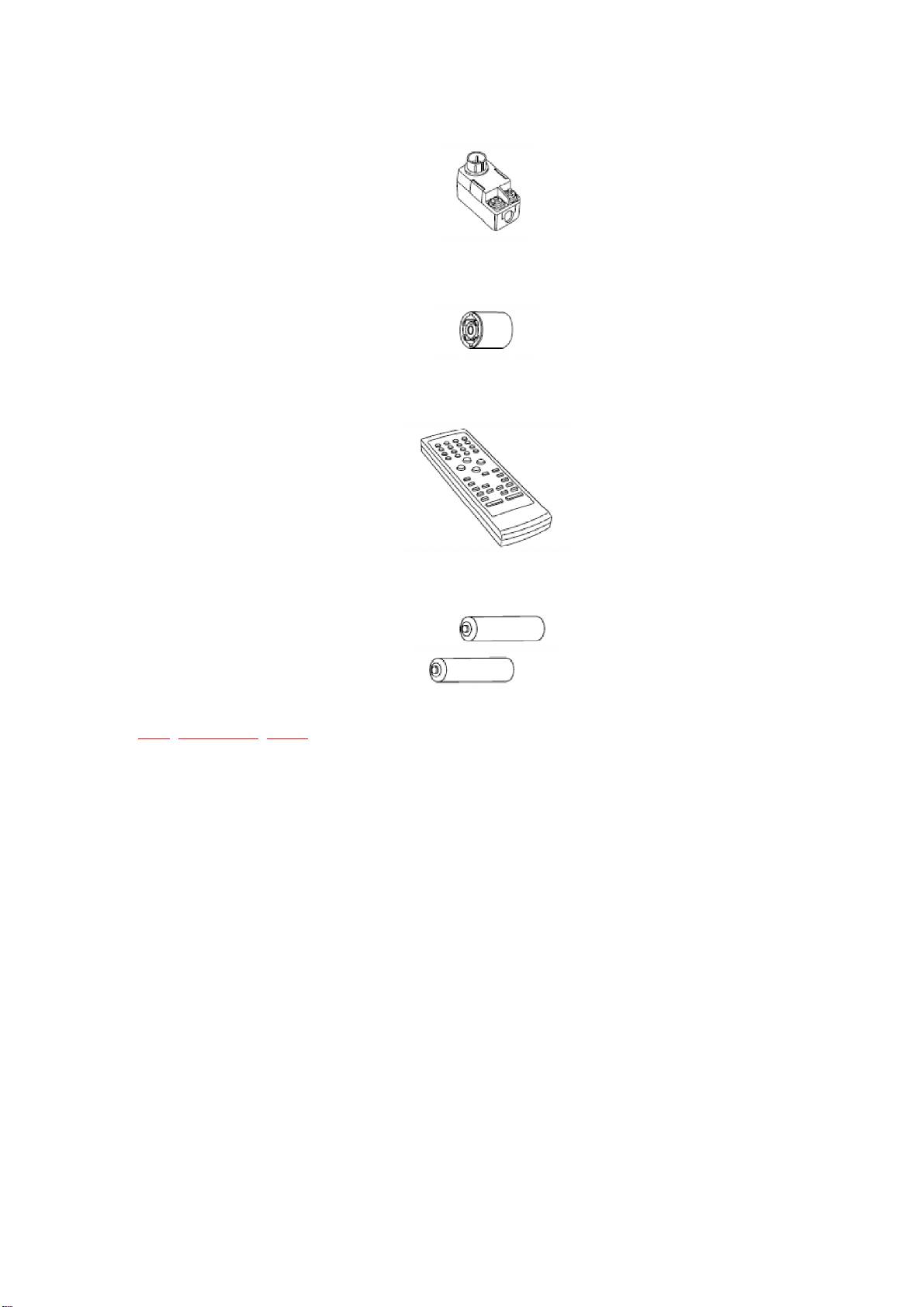
Buttons indicated in black circles (for example : 3) function in
the same way as the controls on the main unit.
No. Name
CUnit on/off button ( )
Use this button to turn the unit on and off when the unit’s
[ /I] button is on ( ).
DNumeric buttons (1–0, ≥10)
Remote control
77
77
7Equipment Connections
Make sure that the power supply for all components has been
turned off before making any connections.
Connect to an amplifier
1
White (L)
Red (R)
To make a digital recording
Connect this unit to digital recording equipment
(MD or DAT deck) through “OPTICAL OUT
AUDIO”.
To download DAB data
Connect this unit to a DAB data system through
“OPTICAL OUT RDI”.
(Carefully read the operating instructions of the equipment
you intend to connect.)
Dust-protection caps
Remove the dust-protection caps (a) before connecting the
optical cables.
OPTICAL OUT terminals not in use should be covered by a
dust-protection cap.
Note
2
DIGITAL
OPTICAL
IN
DIGITAL
OPTICAL
IN
AC IN
LINE OUT
OPTICAL OUT
AUDIO RDI
L
R
DAB ANT AM ANT FM ANT
EXT LOOP 75
75
TUNER
a
A
BC
1
2
3
Connect the AC mains lead.
Connect the AC mains lead only after all other connections
have been made.
Insertion of Connector
Even when the connector is per-
fectly inserted, depending on the
type of inlet used, the front part of
the connector may jut out as
shown in the drawing.
However there is no problem
using the unit.
3
Connector
Approx. 6 mm
Appliance inlet
Amplifier (not included)
Optical cables
(not included)
Digital recording equipment
(not included)
AC mains lead
(included)
This unit
Stereo phono cable (included)
Stereo phono cable
(included)
(United Kingdom only)
BE SURE TO READ THE CAUTION FOR THE AC
MAINS LEAD BEFORE CONNECTION.
DAB data system, etc.
(not included)
To household
mains socket
77
77
7Antenna Connections
FM indoor antenna (included)
Fix the other end of the antenna where reception is best.
Installing outdoor antennas
The included antennas are sufficient under normal conditions.
FM ANT
75
A
Adhesive tape
FM indoor antenna
(included)
AM loop antenna (included)
Use the holder to attach to the back panel (a), or use a screw to
attach it to a wall or pillar (b).
AM ANT
EXT LOOP
ab
?
LOOP ANT
HOLDER
1
2
3
B
AM loop antenna
(included)
or
Screw
(not included)
DAB “T” antenna (included)
The cross bar of the T must be horizontal and kept firmly stretched.
Find a position with good reception.
There is a function on the unit to check signal quality.
DAB ANT
75
C
DAB “T” antenna
(included)
Adhesive tape
FM outdoor antenna (not included)
T
Disconnect the FM indoor antenna.
Note
FM ANT
75
A
FM outdoor antenna
(not included)
75 Ωcoaxial cable
(not included)
(United Kingdom
only)
Use the FM antenna
plug adaptor (included)
AM outdoor antenna (not included)
Run a piece of vinyl wire horizontally across a window or other con-
venient location.
T
Leave the loop antenna connected.
T
Disconnect the antenna when the unit is not in use. Do not use
the antenna during an electrical storm.
Note
5–12m
AM ANT
EXT LOOP
B
AM outdoor antenna
(not included)
Continued on next page