Manual-4
OPERATING INSTRUCTIONS
Once all of the inputs and outputs are properly connected in
accordance with the preceding section, normal operation of the
DC 24 should be achievable. If any of the following procedures
do not appear to produce the required results, take a step back-
wards and check your wiring.
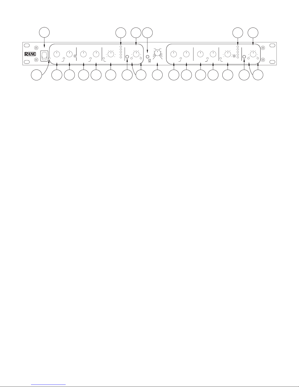
PRE-FLIGHT CHECKLIST
Before proceeding, it’s a good idea to turn the control knobs
to the following positions:
1. POWER...off
2. GATE / EXPANDER THRESHOLD...full CCW
3. GATE / EXPANDER RATIO...full CCW
4. COMPRESSION THRESHOLD...full CCW
5. COMPRESSION RATIO...full CCW
6. LIMIT THRESHOLD...full CW
7. OUTPUT LEVEL...centered in its detent
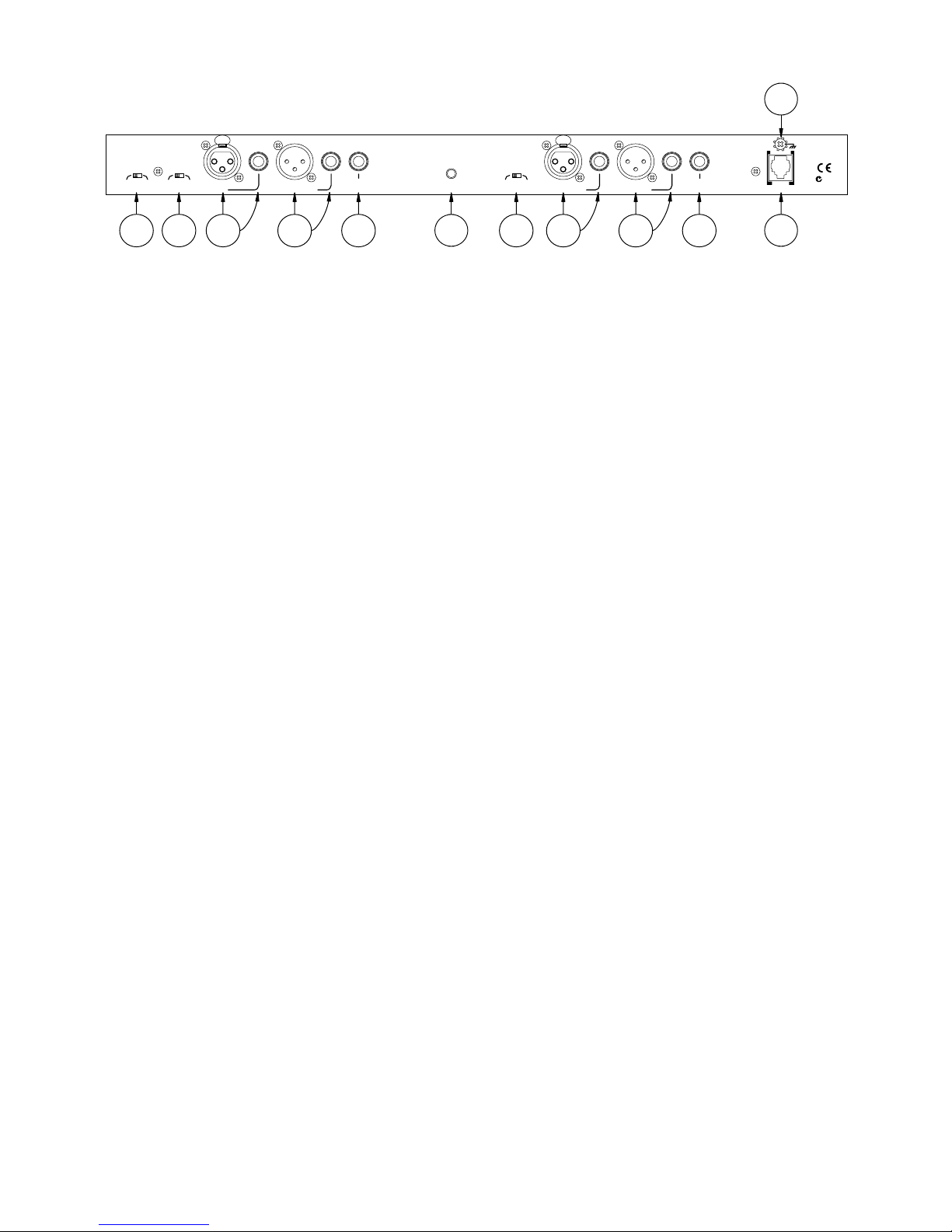
8. Set all pushbuttons on the front and rear to their out positions.
9. Set the OUTPUTS slide switch to SEPARATE.
10. Set the gain TRIM switches to +4 dBu.
LIMITING
With all of the preceding accomplished, turn the POWER
switch on (be sure your amp is turned down). e DC 24 is now
nothing but a unity gain amplifier. Cycling the BYPASS switches
with audio passing through the unit should yield no difference
in level or sound dynamics. e GAIN REDUCTION meters
should indicate 0 and nothing else. Assuming your input signal
has peaks in excess of -20 dBu, you should be able to rotate the
LIMITER THRESHOLD controls CCW and see some gain
reduction occur on the meter simultaneously with a randomly
illuminating THRESHOLD LED. You should begin to hear the
difference. Leave these controls at whatever Limit level is appro-
priate for your application.
COMPRESSION
To use the Compressor, set the COMPRESSOR THRESH-
OLD for an appropriate level, you should see the associated LED
illuminate as signal goes above and below this level. e COM-
PRESSOR RATIO control adjusts the gain reduction slope
above the level you have set.
GATE / EXPANDER
e Gate / Expander function works similarly. If the GATE
/ EXPANDER THRESHOLD is still fully CCW, rotate the
GATE / EXPANDER RATIO to its full CW position. Stop
your audio source and you will see the GAIN REDUCTION
LEDs drop to the -24 dB position. is indicates that the Chan-
nel is in the fully gated mode. If you wish to have gating occur at
a higher level, rotate the GATE /EXPANDER THRESHOLD
control CW to a higher level. If you wish to create special effects
with this gate, you may elect to use a lower GATE / EXPAND-
ER RATIO setting. is inhibits full gating by the amount
indicated around the control. Experiment with all the controls to
obtain the required results.
©Rane Corporation 10802 47th Ave. W., Mukilteo WA 98275-5098 TEL 425-355-6000 FAX 425-347-7757 WEB www.rane.com
STERNO
When using the DC 24 as a true stereo (a.k.a. sterno; hey,
lighten up, it’s a joke!) processor, left channel in Channel 1 and
right channel through Channel 2, it is a good idea to operate
the unit in the SLAVE mode to prevent large balance and image
shifts. While in the SLAVE mode, both channels attenuate by
exactly the same amount when the Gate and Compressor work,
maintaining the stereo image.
ATTENTION SHOPPERS
is seems like a good place to throw in a few words of cau-
tion. e DC 24 allows a great deal of flexibility. As such, it also
allows one to come dangerously close to completely destroying
an otherwise respectable audio signal if some thought and care
is not put into the operation of the unit. ere are combinations
of THRESHOLD and RATIO settings on the Gate, Expander
and Limiter which allow each to fight the others and in some
cases completely cancel. e same caution applies to any signal
processor, such as an equalizer or crossover, however these are
a bit more intuitive and less likely to be used in a destructive
manner. Just be gentle at first and you should not encounter too
much difficulty. If you become overwhelmed, go back to the
PRE-FLIGHT CHECKLIST for initial control settings and
start over.
BYPASS SWITCHES IN CROSSOVER & COMBINE MODES
Crossover Mode. Do not use the BYPASS switches when in
the CROSSOVER mode. Use of BYPASS in the crossover mode is
potentially destructive since these switches route full bandwidth
audio to drivers designed only for a limited frequency range.
(CH 2 BYPASS is automatically defeated, but Ch. 1 is still active
— do not engage the CH 1 BYPASS for any reason.)
Combine Mode. As more users (particularly bass guitar
players) discover new applications for this mode, they want to
use BYPASS as an aid in optimizing settings. Unfortunately,
the BYPASS switches do not operate in the COMBINE mode;
however, a simple trick solves the problem:
1. Permanently engage the CH 1 BYPASS switch.
2. Patch CHANNEL 1 OUTPUT to CHANNEL 2 INPUT
using either the ¼" TRS or the XLR jacks. Be sure to use 2-
conductor shielded cable.
3. e CH 2 BYPASS switch now operates in the COMBINE
mode.
RESOURCES
For additional explanations, tips and assistance, see “e
DC 24 Users Guide” and “Good Dynamics Processing.” Both of
these RaneNotes are available on the Rane website.
103166