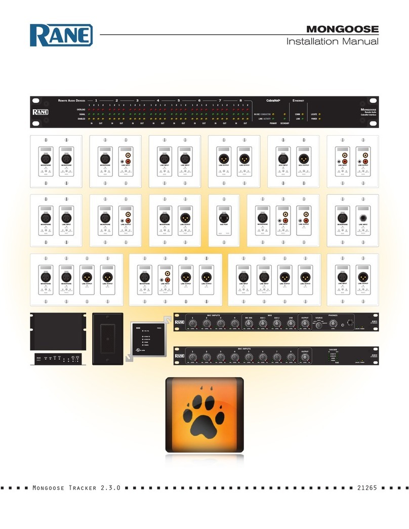
Rane MONGOOSE Guide

MONGOOSE
Design Manual
1
M
ONGOOSE
Remote Audio
CobraNet Interface
1
12345678
REMOTEAUDIO DEVICES ETHERNET
IN OUT IN OUT IN OUT IN OUT IN OUT IN OUT IN OUT IN OUT
OVERLOAD
SIGNAL
ENABLED
IN USE / CONDUCTOR
LINK / ACTIVITY
COMM
LINK
LOCATE
POWER
212 1212 1212 1212 1212 1212 1212 121
PRIMARY
SECONDARY
2
CobraNet®
■ ■ ■ ■ Mongoose Tracker 2.1.0 ■ ■ ■ ■ ■ ■ ■ ■ ■ ■ ■ ■ ■ ■ ■ ■ ■ ■ ■ ■ ■ ■ ■ ■ ■ ■ ■ ■ ■ ■ ■ ■ ■ ■ ■ ■
1
2
MIC
INPUT
LINE
INPUT
POWER COMM
AUDIO
RX
AUDIO
TX
OUTPUT
SIG / OL
INPUT
SIG / OL
1
2
LINE INPUTLINE INPUT
RAD3
POWERCOMM
SIG / OLSIG / OL
AUDIO RX AUDIO TX
MICROPHONE MICROPHONE
RAD1
SIG / OL
AUDIO RX AUDIO TXPOWERCOMM
SIG / OL
LINE OUTPUT LINE OUTPUT
RAD4
POWERCOMMAUDIO RX AUDIO TX
MICROPHONE LINE INPUT
RAD2
SIG / OL
AUDIO RX AUDIO TXPOWERCOMM
SIG / OL
MICROPHONE LINE OUTPUT
RAD9
SIG / OL
AUDIO RX AUDIO TXPOWERCOMM
SIG / OL
LINE OUTPUTLINE INPUT
RAD6
SIG / OL
AUDIO RX AUDIO TXPOWERCOMM
SIG / OL
LINE OUTPUTMICROPHONE
RAD8
SIG / OL
AUDIO RX AUDIO TXPOWERCOMM
SIG / OL
RAD11
MICROPHONE LINE INPUTLINE OUTPUT
SIG / OL
AUDIO RX AUDIO TXPOWERCOMM
SIG / OL SIG / OL
MICROPHONE LINE INPUTLINE OUTPUT LINE OUTPUT
RAD14
SIG / OL
AUDIO RX AUDIO TXPOWERCOMM
SIG / OL SIG / OLSIG / OL
LINE INPUTLINE INPUTLINE OUTPUT LINE OUTPUT
RAD15
SIG / OL
AUDIO RX AUDIO TXPOWERCOMM
SIG / OL SIG / OLSIG / OL
MICROPHONE LINE INPUT
RAD18
SIG / OL
AUDIO RX AUDIO TXPOWERCOMM
SIG / OL
MICROPHONE MICROPHONE LINE OUTPUT LINE OUTPUT
RAD12
SIG / OL
AUDIO RX AUDIO TXPOWERCOMM
SIG / OL SIG / OLSIG / OL
topfront RAD16
MICROPHONE LINE INPUT
RAD7
POWERCOMM
SIG / OLSIG / OL
AUDIO RX AUDIO TX
AES3 INPUTAES3 OUTPUT
RAD5
AUDIO RX AUDIO TXPOWERCOMM
LOCK
RAD PORT
RADX
LINE INPUTLINE OUTPUT
RAD23
SIG / OL
AUDIO RX AUDIO TXPOWERCOMM
SIG / OL
AM1
AUTOMIXE
R
P
O
WERL
OC
AT
E
PHONE
S
M
I
X
SI SIG OLLEVEL
S
IG OLLEVEL SI
G
OLLEVEL
MIC MI
X
SI LEVEL
AUX
1
SI LEVEL
AUX
2
SI LEVEL
US
B
SI LEVEL
OUTPUT
SI LEVEL
AUX 2
AUX
1
US
B
M
I
CS
O
UTPU
T
SOURCE
LEVELLEVEL
MIC INPUT
S
1
2
3
4
AM2
AUTOMIXE
R
POWER
LOCAT
E
OU
T
I
N
C
A
SC
AD
E
R
AD
1
MI
C
INPUT
S
SI
2
SI LEVEL
3
SI LEVEL
4
SI LEVEL
5
SI LEVEL
6
SI LEVEL
7
SI LEVEL
8
SI LEVEL
O
UTPUT
SI LEVELLEVEL
POWER
COM
M
AU
DI
O
RX
AUDIO TX

MONGOOSE
Design Manual
2
Contents
List of Figures................................................................................................................................................. 3
SECTION 1: INTRODUCTION..................................................................................................................... 4
Purpose of this Document........................................................................................................................ 4
Rane Mongoose Documentation Set................................................................................................... 5
System Requirements................................................................................................................................ 5
SECTION 2: UNDERSTANDING THE MONGOOSE SYSTEM...................................................... 6
The Big Picture.............................................................................................................................................. 6
The Benefits of a Mongoose.................................................................................................................... 8
Components of a Mongoose System................................................................................................... 9
The Mongoose Host Device..................................................................................................................... 10
Remote Audio Devices............................................................................................................................... 14
Mongoose Tracker Software.................................................................................................................... 16
Understanding how the Audio is Routed............................................................................................ 17
SECTION 3: DESIGNING YOUR SYSTEM............................................................................................. 25
Tips and Recommendations .................................................................................................................... 25
Key Design Decisions to Make................................................................................................................ 26
Latency.............................................................................................................................................................. 28
Example Applications ................................................................................................................................. 29
RAD to RAD Using a Single Mongoose (Tie-Line)......................................................................... 29
RAD to DSP (or other device) via CobraNet using a Single Mongoose................................ 32
RAD to DSP (or other device) using Multiple Mongoose Devices .......................................... 35
CobraNet Bundle to CobraNet Bundle................................................................................................ 41
SECTION 4: INSTALLATION AND CONFIGURATION ISSUES.................................................... 45
Key Installation Tasks and Recommended Work Flow ................................................................. 45
Installation Best Practices ......................................................................................................................... 46
Installing the Mongoose Off-site ............................................................................................................ 46
Connecting the Mongoose to a Network – Best Practices ......................................................... 47
About the Control Network ..................................................................................................................... 47
About the CobraNet Network.................................................................................................................. 48
Designing Each Network........................................................................................................................... 48
SECTION 5: INSTALLING AND USING THE MONGOOSE TRACKER..................................... 55
Installing Mongoose Tracker.................................................................................................................... 55
Starting Mongoose Tracker...................................................................................................................... 56
Working with Configuration Files........................................................................................................... 57
Configuration Issues to Note ................................................................................................................... 57
Distinguishing Between Live Device Settings Versus Configuration File Settings ........... 58
Using the Configuration File During Installation.............................................................................. 58
Creating the Configuration File............................................................................................................... 59
Generating RAD Labels ............................................................................................................................. 59
Updating (or Rolling Back) the Mongoose Firmware ................................................................... 61
Uninstalling Mongoose Tracker .............................................................................................................. 62
INDEX.................................................................................................................................................................... 63

MONGOOSE
Design Manual
3
List of Figures
Figure 1: Audio system using analog cables............................................................................................................................................................ 6
Figure 2: Audio system using Mongoose and RADs ............................................................................................................................................ 7
Figure 3: Front panel of the Mongoose...................................................................................................................................................................... 10
Figure 4: Rear panel of Mongoose .............................................................................................................................................................................. 12
Figure 5: Block diagram of Mongoose ...................................................................................................................................................................... 13
Figure 6: Purpose of each CAT 5 twisted pair.......................................................................................................................................................... 14
Figure 7: Remote Audio Device..................................................................................................................................................................................... 15
Figure 8: Back of a RAD.................................................................................................................................................................................................... 16
Figure 9: Mongoose Tracker main window............................................................................................................................................................... 17
Figure 10: Simplified view of an audio routing matrix.......................................................................................................................................... 18
Figure 11: Mongoose Tracker audio routing matrix.............................................................................................................................................. 18
Figure 12: Hardware view of routing audio between two RADs that are connected to the same Mongoose.............................. 19
Figure 13: Simple view and actual view of matrix routing signal from RAD to RAD on a single Mongoose ................................. 19
Figure 14: Hardware view of routing audio between two RADs that are connected to different Mongoose devices............... 20
Figure 15: Simple view and actual view of matrices routing signal from RAD to RAD on different Mongoose devices .......... 21
Figure 16: Hardware view of routing audio between a RAD and a CobraNet device ............................................................................. 22
Figure 17: Simple view and actual view of matrix routing signal from RAD to CobraNet device....................................................... 22
Figure 18: Hardware view of routing aggregated RAD signals from different Mongoose devices to a CobraNet device....... 23
Figure 19: Matrices routing aggregated RAD signals from different Mongoose devices to a CobraNet device......................... 24
Figure 20: CAD drawing - Mongoose front............................................................................................................................................................... 25
Figure 21: CAD drawing - Mongoose back .............................................................................................................................................................. 25
Figure 22: CAD drawing - RAD1................................................................................................................................................................................... 25
Figure 23: Maximum distance covered in CAT 5 scenario ................................................................................................................................. 27
Figure 24: Maximum distances covered using fiber optic cable...................................................................................................................... 27
Figure 25: One-line drawing for Saint Dawkins Church tie-line application ............................................................................................... 29
Figure 26: Floor plan of Saint Dawkins Church tie-line application................................................................................................................ 30
Figure 27: Shop drawing for Saint Dawkins Church tie-line application ...................................................................................................... 30
Figure 28: Configuration for Saint Dawkins Church tie-line application....................................................................................................... 31
Figure 29: One-line drawing for cafetorium example application ................................................................................................................... 32
Figure 30: Floor plan of cafetorium example application (illustrating RAD to DSP routing) ............................................................... 33
Figure 31: Shop drawing for cafetorium example application (illustrating RAD to DSP routing)...................................................... 34
Figure 32: Configuration for Cafetorium (routing RADs from a single Mongoose to and from a CobraNet device)................. 34
Figure 33: One-line drawing for hotel example application............................................................................................................................... 36
Figure 34: Floor plan of hotel illustrating routing of RADs from multiple Mongoose devices to DSP equipment...................... 37
Figure 35: Shop drawing of hotel illustrating routing of RADs from multiple Mongoose devices to DSP equipment.............. 38
Figure 36: Configuration for Mongoose A in hotel (RADs from multiple Mongoose devices to and from CobraNet).............. 39
Figure 37: Configuration for Mongoose B in hotel (RADs from multiple Mongoose devices to and from CobraNet).............. 40
Figure 38: One-line drawing for Kipling College music and paging system............................................................................................... 41
Figure 39: Floor plan for Kipling College music and paging system - illustrating Bundle aggregation........................................... 42
Figure 40: Shop drawing for Kipling College example application – illustrating Bundle aggregation............................................. 43
Figure 41: Configuration for student union of Kipling College (two Mongoose devices into one CobraNet Bundle) .............. 44
Figure 42: Configuration for cafeteria of Kipling College (two Mongoose devices into one CobraNet Bundle)......................... 44
Figure 43: Adjusting RAD to make it flush with wall ............................................................................................................................................. 46
Figure 44: Control Network - direct connection..................................................................................................................................................... 49
Figure 45: CobraNet Network - direct connection................................................................................................................................................ 49
Figure 46: Control Network - isolated for audio network ................................................................................................................................... 50
Figure 47: CobraNet Network - isolated for audio network............................................................................................................................... 51
Figure 48: Control Network - integrated with existing corporate network .................................................................................................. 52
Figure 49: Control and CobraNet Networks - on same switch but isolated via VLAN............................................................................ 53

MONGOOSE
Design Manual
4
SECTION 1: INTRODUCTION
Perhaps you are familiar with the furry yet ferocious mongoose, a member of the Herpestidae family that
is known for its agility and cunning – so fast and smart that it can capture venomous snakes, even king
cobras. But did you know that a Rane Mongoose can perform a similar feat with your CobraNet network?
Now we’re certainly not insinuating that CobraNet is venomous! In fact, we’d say just the opposite.
CobraNet is an excellent technology for distributing digital audio. But its 8-channel Bundle architecture
can be difficult to utilize and tame, especially if you have only a few channels to distribute from within a
given space. If this describes your situation, you’ve come to the right place.
e Rane Mongoose system, designed to wrestle and control your CobraNet Bundles and other analog
cables, distributes digital audio signals over shielded CAT 5e cable between low channel count locations
and the rest of your audio system. To accomplish this, it utilizes a network of up to eight Remote Audio
Devices (or RADs) that are connected via CAT 5 cable to a single Mongoose host. A RAD, designed to
mount inside a standard US two or four gang switchbox, uses high value, professional quality technology to
transmit and receive up to four channels of digital audio – two channels in each direction. e Mongoose
to which these RADs are connected, serves as the host that controls and aggregates the channels and
connects them to the rest of the audio system.
Purpose of this Document
If you design audio systems and are planning to incorporate a Mongoose/RAD network into your next
design, then this design manual is for you. It is intended to help you through the design process by giving you
background information on the Mongoose system as well as the basic details of how CobraNet works (in
case you are unfamiliar with this digital networking technology). is manual details the benefits of using
a RAD network and illustrates how to effectively utilize these benefits in various audio applications. It also
includes suggested best practices, sample drawings and Mongoose configurations, and key information
you should provide to your installers.
PLEASE READ THIS: If you’re short on time and are tempted to jump right in without reading this
manual, we recommend that you at least skim "SECTION 3: DESIGNING YOUR SYSTEM" on page 25
and, most importantly, read about configuration files in "SECTION 5: INSTALLING AND USING THE
MONGOOSE TRACKER" on page 54. However, unless you need to get this design out the door in the next
hour, we strongly recommend that you review the entire manual. It contains valuable information that will
help ensure a smooth design and installation process.

MONGOOSE
Design Manual
5
Rane Mongoose Documentation Set
In addition to this design manual, the Rane documentation set includes an installation manual and a
software help system built into the Mongoose Tracker.
e Mongoose Installation Manual (available on the Rane website) explains the details of racking the
Mongoose and connecting it to the network, installing the RAD devices and connecting them to the
Mongoose, and troubleshooting any connection or audio problems that arise.
e software help system, embedded in the Mongoose Tracker software application, contains tutorial
simulations to introduce you to the software, information on Mongoose and RAD configuration, detailed
information about the user interface as well as detailed procedures for accomplishing specific tasks.
We also recommend you periodically check www.rane.com/mongoose at the Rane website for the latest
information on the system (for example, software updates, the release of new RAD models, line art, etc.).
System Requirements
To include a Mongoose/RAD network in an audio system, the system must meet the following requirements:
If you plan to use CobraNet to communicate between a Mongoose and other audio devices, those devices
must be CobraNet-enabled.
• You must have access to a computer running Microsoft Windows® XP (Service Pack 2 or higher)
or any version of Vista or Windows 7 (including 64-bit). e computer must also have an Ethernet
port, which you use to connect the computer to the Mongoose (either directly or via an Ethernet
network). is connection is necessary for using the Mongoose Tracker software to load configuration
information into the device and also for monitoring detailed status information. Note that some status
information is visible on the hardware itself.
• You must have administrative rights to install (or upgrade) the Mongoose Tracker software, but you
do not need administrative rights to run the software. Note that you also need administrative rights to
manually start or stop the RaneLink service (a Windows service installed with Mongoose Tracker that
runs at system boot up to ensure the establishment of communications between Mongoose Tracker
and the Mongoose). Manual control of this service is rarely needed.
• Most RADs require two, three, or four-gang standard switchboxes (for installation into a wall). e
switchbox must have a minimum depth of 2¼" (57 mm).
Windows is a registered trademark of Microsoft Corporation in the United States and other countries.
Mac and Mac OS are trademarks of Apple Inc., registered in the United States and other countries.

MONGOOSE
Design Manual
6
SECTION 2: UNDERSTANDING THE MONGOOSE SYSTEM
Rane understands the pain and expense of pulling and managing miles of analog cable throughout a large
audio installation, not to mention the potential for inferior sound quality. e advent and rapid adoption
of digital audio networking has almost ended this cabling and quality nightmare – but not quite. You
have probably utilized one or more of the networking solutions that exist today – for example, CobraNet,
Ethersound, and others. But, as discussed in the introduction, these solutions aren’t appropriate in all
situations. Because placing just a few channels on a large bandwidth network Bundle is inefficient and
expensive, you are probably still using analog cabling in low channel count applications.
Since you’re reading this manual, we can assume that you are seriously considering replacing all this
cabling with less expensive shielded CAT 5e cables and distributing the audio digitally via a RAD network.
Congratulations! You’ve made a wise choice. To help make this transition from analog to digital and from
older audio technology to new, this section provides a thorough explanation of the entire Mongoose
system – as well as suggestions for incorporating it into your larger audio system as efficiently as possible.
The Big Picture
Before diving into the details, let’s take a look at the big picture. e following illustration shows an audio
system that uses analog cables to connect scattered channels to the rack room equipment
:
Auditorium
Meeting Room
Control Room Rack
OFF
0
+6
OFF
0
+6
OFF
0
+6
OFF
0
+6
OFF
0
+6
OFF
0
+6
OFF
0
+6
OFF
0
+6
100
2
4
8
6
100
2
4
8
6
100
2
4
8
6
100
2
4
8
6
100
2
4
8
6
LOWHIGHMIDLOW HIGHMIDLOW HIGHMIDLOW HIGHMID
OUTPUT
EFFECTS
LEVELLEVEL LEVELLEVEL LEVELOL OL OL OL OL
WETDRY
POWER
1234
MLM 42S
MIC/LINEMIXER
Mic 1
MIC CONDUIT
LINE CONDUIT
CobraNet® DSP
MIC CONDUIT
LINE CONDUIT
DATA CONDUIT
CobraNet® Network
CobraNet® Mic Mixer
CobraNet® DSP
Figure 1: Audio system using analog cables

MONGOOSE
Design Manual
7
Now take a look at the difference when you replace the analog connections with a RAD network:
Auditorium
Meeting Room
Control Room Rack
OFF
0
+6
OFF
0
+6
OFF
0
+6
OFF
0
+6
OFF
0
+6
OFF
0
+6
OFF
0
+6
OFF
0
+6
100
2
4
8
6
100
2
4
8
6
100
2
4
8
6
100
2
4
8
6
100
2
4
8
6
LOWHIGHMIDLOW HIGHMIDLOW HIGHMIDLOW HIGHMID
OUTPUT
EFFECTS
LEVELLEVEL LEVELLEVEL LEVELOL OL OL OL OL
WETDRY
POWER
1234
MLM 42S
MIC/LINEMIXER
CobraNet® DSP
DATA CONDUIT
DATA CONDUIT
CobraNet® Network
M
ONGOOSE
Remote Audio
CobraNet Interface
1
12345678
REMOTEAUDIO DEVICES ETHERNET
IN OUTINOUT IN OUTINOUT IN OUTINOUT IN OUTINOUT
OVERLOAD
SIGNAL
ENABLED
IN USE / CONDUCTOR
LINK / ACTIVITY
COMM
LINK
LOCATE
POWER
21212121212 1212 1212 1212 1212 121
PRIMARY
SECONDARY
2
CobraNet®
LINEOUTPUT LINE OUTPUT
RAD4
RAD4
POWERCOMMAUDIORX AUDIOTX
LINEOUTPUT LINE OUTPUT
RAD4
RAD4
POWERCOMMAUDIORX AUDIOTX
LINEOUTPUT LINE OUTPUT
RAD4
RAD4
POWERCOMMAUDIORX AUDIOTX
MICROPHONE MICROPHONE
RAD1
RAD1
SIG/ OL
AUDIORX AUDIO TXPOWERCOMM
SIG/ OL
MICROPHONE MICROPHONE
RAD1
RAD1
SIG/ OL
AUDIORX AUDIO TXPOWERCOMM
SIG/ OL
MICROPHONE MICROPHONE
RAD1
RAD1
SIG/ OL
AUDIORX AUDIO TXPOWERCOMM
SIG/ OL
MICROPHONE MICROPHONE
RAD1
RAD1
SIG/ OL
AUDIORX AUDIO TXPOWERCOMM
SIG/ OL
MICROPHONE LINEINPUT
RAD2
RAD2
SIG/ OL
AUDIORX AUDIO TXPOWERCOMM
SIG/ OL
Figure 2: Audio system using Mongoose and RADs
As you can see, the Mongoose corrals and controls the low count channels in your audio system, aggregating
them so you can more efficiently utilize your CobraNet network. Each RAD input amplifies, digitizes, and
transmits the digital audio via CAT 5 to its host Mongoose, whereupon it can be routed to another RAD,
to a CobraNet Bundle, or both. Each output RAD receives via CAT 5 a digital signal and converts it to
analog for delivery to the attached device.
e specific details of the Mongoose and its associated RADs are explained in "Components of a Mongoose
System" on page 9, but you may first want to review the primary advantages to implementing this system.

MONGOOSE
Design Manual
8
The Benefits of a Mongoose
To most effectively design a system containing a RAD network, you need to understand its benefits so you
can take full advantage of them. For example, when using RADs, not only can you place line-level audio
and a microphone within the same conduit, you can place it on the same cable!
Following is a brief discussion of how key aspects of an audio system are handled within a Mongoose
system versus a typical analog system.
Less Expensive Cabling and Conduit
e foremost advantage of the Mongoose system is its use of CAT 5 cables for audio distribution. We don’t
have to tell you the cost benefits of using CAT 5 versus shielded audio cables and conduit. But bear with
us. Since we’re highlighting the benefits of a Mongoose, we’ll expound a bit more on the cost savings. Not
only is CAT 5 cable much less expensive than shielded analog cable, use of CAT 5 cable eliminates the
need for conduit. In addition to that, a RAD can transmit up to four channels (two input, two output) over
one CAT 5 cable. To top things off, the RAD is also able to transmit power and a data signal – all on that
same CAT 5 cable. To provide all this functionality in an analog world would require pulling six times the
amount of cabling needed by the RAD network as well as the use of conduit to house all that cabling! So
not only is the medium itself less expensive, but the difference in time and labor costs is huge. As a matter
of fact, by using CAT 5 cables, it may be possible for some economies of scale – why not have the IT folks
pull and terminate your CAT 5 cable at the same time they pull the data wires for the building?
Simpler Cable Termination
Your installers will be happy to know that they can toss their soldering irons aside. Terminating connections
in the Mongoose system involves nothing more than the simple process of crimping CAT 5 cables. And
unlike soldering, the crimping process does not require electricity.
An added benefit is the automatic testing that the Mongoose performs on each connection. When
the installer terminates and connects the CAT 5 cable to the RAD, the Mongoose automatically tests
the connection (assuming, of course, that the Mongoose is connected and powered on). e status of
the connection is immediately reported via the status lights on the RAD. If there’s a problem with the
connection, it can often be solved by simply re-crimping the cable – a much easier process than having to
re-solder a connection.
Better Sound Quality
Susceptibility to noise interference is much greater with analog than with digital transmission. Replacing
your analog channels with a RAD network immediately provides you with far superior sound quality –
especially if you’re transmitting the signal over substantial distances. In addition to eliminating noise
interference, the RAD’s transmitters and receivers have a high common mode range.
Digitizing the audio at the wall eliminates the mounting, expense, and trouble of isolation transformers
traditionally used in analog applications. Plus, passing low frequencies through analog isolation
transformers requires large cores and therefore more space. RADs save the space and pass those low
frequency Barry White vocal pronouncements to your application’s dual 18-inch subwoofers without
compromise.

MONGOOSE
Design Manual
9
Simpler and Faster to Change Audio Routing
In an analog system, audio is often routed by hardwiring the necessary connections. erefore, to
change the routing, you must change the wiring – often a tedious and time-consuming process. With the
Mongoose system, however, the audio routing is handled by software. To change the routing, you simply
point and click within the Mongoose software application. Audio routing changes are literally as simple
as the click of a mouse.
Easier Troubleshooting
Have you or your installers ever been baffled by an audio connection that fails to work? You’ve pulled
all the cables, installed all the equipment, and, when you flip the switch, you hear silence instead of the
glorious sound you expected. You must then retrace your steps and try to locate the problem. In an analog
system, wiring mistakes and broken cables can be quite difficult to troubleshoot. e ends of the wires are
often hundreds of feet apart in completely different rooms. In a RAD network, the equipment contains
status indicators that immediately notify you if there’s a problem. For example, on a single RAD, a power
indicator tells you if a power signal is present, a communications indicator tells you if a data signal is
present, and an Audio Rx and an Audio Tx indicator tell you if an incoming or outgoing audio signal is
present. e Mongoose itself contains numerous status indicators as well. And the Mongoose Tracker
software, used primarily for configuring the system, provides even more troubleshooting information,
allowing you to troubleshoot your system from one location!
Components of a Mongoose System
A Mongoose system contains three primary components:
1. e host device (called the Mongoose) to which you can connect up to eight RADs. You can
then connect the Mongoose to your Ethernet network (for setup and control) and to additional
CobraNet-enabled audio equipment. e Mongoose is typically located in the audio rack room.
2. e RADs that serve as the input/output devices located in the rooms in which you want to send
or receive audio.
3. e Mongoose software (called the Mongoose Tracker), which you use to configure and troubleshoot
the system.
Another key player in a Mongoose system is the CobraNet network. Although there may be a few scenarios
in which CobraNet is not required (for example, sending audio from one RAD to another RAD on the same
Mongoose), in most applications you will want to take advantage of the power of CobraNet. Combining a
RAD and CobraNet network allows you to digitize and aggregate scattered channels and efficiently route
them to any location within the entire audio system.

MONGOOSE
Design Manual
10
The Mongoose Host Device
e primary purpose of the Mongoose host device is to connect up to eight RADs to a CobraNet network.
It is typically housed in the audio rack room along with the DSP and other audio equipment. In addition
to hosting the RADs, the Mongoose does the following:
• Provides power to the connected RADs
• Stores configuration settings for itself and for each of the connected RADs
• Provides a connection to an Ethernet network (for control of the Mongoose and RADs)
• Provides connections to both a primary and secondary (backup) CobraNet network
• Displays various status indicators (LEDs) providing information about the health of the system
Front Panel Description
MONGOOSE
Remote Audio
CobraNet Interface
1
12345678
R
EMOTE
A
UDIO
D
EVICES
E
THERNET
IN OUT IN OUT IN OUT IN OUT IN OUT IN OUT IN OUT IN OUT
OVERLOAD
SIGNAL
ENABLED
IN USE / CONDUCTOR
LINK / ACTIVITY
COMM
LINK
LOCATE
POWER
212 1212 1212 1212 1212 1212 1212 121
PRIMARY
SECONDARY
2
CobraNet
®
1 2
r
aN
et
t
®
3
RNE
T
4
Figure 3: Front panel of the Mongoose
1e Remote Audio Devices status indicators provide information about the RAD audio channels.
e numbers 1 through 8 at the top of the front panel correspond to the RAD ports 1 through 8
on the back of the Mongoose. For example, the status indicators for number 1 provide information
about the RAD connected on port 1.
Under each RAD number are four audio channels, two input and two output. ese represent the
maximum number of channels a RAD is capable of transporting. However, not all RAD models use
all four channels. For example, the RAD1 model provides two microphone inputs, so for that model,
only the two columns of indicators labeled IN would be active.
ere are three types of indicators:
�Overload LED (red) –indicates that the channel is experiencing a signal overload.
�Signal LED (green) – indicates the presence of an audio signal on this channel
�Enabled LED (yellow) – indicates the availability of the associated audio channel. If a RAD is
connected on this port and all Enabled lights are off, this indicates a problem with the CAT 5
connection or with the RAD. If the Enabled LEDs are flashing, this indicates that the physical
RAD model does not match the RAD model specified for this port in the Mongoose’s configura-
tion.

MONGOOSE
Design Manual
11
2e CobraNet status indicators provide information about the Mongoose’s CobraNet connection.
ere are two sets of indicators for each CobraNet network – Primary and Secondary. Of course,
the secondary network indicators function only if you have implemented a secondary (or backup)
CobraNet network.
� In Use/Conductor LED (yellow) – indicates that the CobraNet port is in use, in other words Co-
braNet packets are being sent or received by the Mongoose. If the Mongoose has auto-negotiated
to be the CobraNet Conductor, this LED flashes (indicating it is both in use and is the Conduc-
tor). If you have connected both the primary and secondary CobraNet ports, only one of your
CobraNet networks will be active (or in use) at any given time, therefore, only one In Use/Con-
ductor indicator will be active.
�Link/Activity LED (green) – indicates the CobraNet network is connected, and flashes if there
is activity on the network. If the Mongoose is connected to another CobraNet device or network
switch but the Link LED is off, this indicates a problem with the connection. If you have connect-
ed both the primary and secondary CobraNet ports, the Link LED for both ports should be on.
3 e Ethernet status indicators provide information about the Mongoose’s Ethernet connection.
�Comm LED (yellow) – flashes when the Mongoose is sending or receiving network packets to or
from the Mongoose Tracker software.
�Link LED (green) – indicates if the Ethernet network is connected. If the Mongoose is connected
to an Ethernet network but the Link LED is off, this indicates a problem with the connection.
Note: If an installation does not include an Ethernet network, this indicator is relevant only when
you connect a computer directly to the Mongoose. If the connection is working properly, the
Link LED lights up.
4 e remaining indicators on the front panel are the Locate and Power LEDs:
�Locate LED – flashes green when you place this device in Locate Mode (via the Mongoose
Tracker software). e purpose of this locate functionality is for verification, when working in
the software, of the physical device you are configuring or viewing. is is helpful when you are
working with multiple Mongoose devices. For more information about this functionality, see the
software help system.
� Power LED – indicates the Mongoose is powered on.

MONGOOSE
Design Manual
12
Rear Panel Description
PRIMARY
SECONDARY
IN USE /
CONDUCTOR
LINK /
ACTIVITY
PRIMARY
SECONDARY
ACN 001 345 482
REMOTEAUDIO DEVICESETHERNETETHERNETREMOTEAUDIO DEVICES
MADE
IN
U.S.A.
RANE
CORP.
MONGOOSE
100-240 V
50/60 Hz 40 WATTS
12345678
12345678
THIS DEVICE COMPLIES WITH
PART 15 OF THE FCC RULES FOR
A CLASS 'B' COMPUTING DEVICE.
LOCATE
POWER
LAN
LINK
COMM
POWER
AUDIO TX
AUDIO RX
1
O
N
GOOS
2 3
T
HERN
E
4 5
A
U
DI
O
6
T
HERN
E
7 8
A
U
DI
O
Figure 4: Rear panel of Mongoose
1 Power IEC jack – connects to AC line voltage, 100-240 V, 50-60 Hz.
2 e Power and Locate LEDs on the back panel serve the same purpose as those on the front.
3 e Ethernet Link LED on the back panel serves the same purpose as the one on the front. e
Ethernet LAN LED flashes when the Mongoose detects any Ethernet packets on the network.
4 e CobraNet LEDs (In Use/Conductor and Link/Activity) on the back panel serve the same
purpose as those on the front.
5 e Remote Audio Devices LEDs on the back panel serve a different purpose from the ones on the
front. e front panel LEDs provide information about signal activity on each audio channel. e
back panel LEDs indicate the health of the CAT 5 connection between each RAD and the Mongoose.
Just as on the front panel, these LEDs are numbered 1 through 8 which correspond to the numbered
ports on the device. Each LED corresponds with one twisted pair within the CAT 5 cable. If the
twisted pair is functioning properly, the LED displays a solid green light.
� Audio Rx LED – lights solidly if the Mongoose’s receive pair is working properly.
� Audio Tx LED – lights solidly if the Mongoose’s transmit pair is working properly.
� Comm LED – lights solidly if the RAD’s data communications pair is working properly.
� Power LED – lights solidly if the Mongoose is supplying adequate power to the RAD port.
6 Ethernet port – used to connect the Mongoose to an Ethernet switch or directly to a computer.
Note that this Ethernet port contains auto-MDIX functionality, which means that if you connect
directly from this port to a computer, you can use either a standard Ethernet patch cable or a
crossover cable to make the connection. e auto-MDIX functionality takes care of coordinating the
proper connection between the devices.
7 CobraNet ports – used to connect the Mongoose to another CobraNet-enabled device or to a
network switch. Use the Primary port to connect your primary CobraNet network. If you have a
backup CobraNet network, connect the Mongoose to it using the Secondary port. Both ports have
the same Media Access Control (MAC) address. Note that the CobraNet ports do NOT contain
auto-MDIX functionality. erefore, if you use this port to connect the Mongoose directly to another
CobraNet device, you MUST use a crossover cable.
8 Remote Audio Devices ports – used to connect each RAD to the Mongoose via a standard CAT5
cable. You must use a standard Ethernet patch cable for this connection.

MONGOOSE
Design Manual
13
Mongoose Block Diagram
Remote Audio Ports
CobraNet
Primary
Secondary
32 x 32
Audio Router
RX 2 Bundles, 16 Channels
TX 2 Bundles, 16 Channels
AES3 RX (x8), 16 Channels
AES3 TX (x8), 16 Channels
CobraNet
Hardware
Chip
Remote
Audio
Tranceivers
Remote
Audio
Tranceivers
Remote
Audio
Tranceivers
Remote
Audio
Tranceivers
Remote
Audio
Tranceivers
Remote
Audio
Tranceivers
Remote
Audio
Tranceivers
Front Panel Indicators Rear Panel Indicators
Ethernet
Ethernet
MAC/Phys
LED Display
Controller
Ethernet
MAC/Phys
Controller
1
2
3
4
5
6
7
Ethernet
MAC/Phys
Remote
Audio
Tranceivers
Port
Power
Supply
8
In Use /
Conductor
Link /
Activity
PrimarySecondary
Ethernet Remote Audio Devices
1
Locate
Power
Lan
Link Comm
Power
Audio TX
Audio RX
Locate
Power
8765324
1
Remote Audio Devices 1-8
In
Overload
Signal
Enabled
2
Ethernet
Out
Comm
Link
12
CobraNet
®
In Use /
Conductor
Link /
Activity
PrimarySecondary
CobraNet
®
2 digital audio channels (Rx)
2 digital audio channels (Tx)
Data communications (COMM)
Power: 24 VDC & ground
Figure 5: Block diagram of Mongoose

MONGOOSE
Design Manual
14
Remote Audio Devices
e primary purpose of a Remote Audio Device (RAD) is to amplify, digitize, and transmit a digital audio
signal via shielded CAT 5e cable to a Mongoose host device. RADs can also receive a digital signal from
the Mongoose and then convert it to analog before sending it to its attached audio equipment. RADs are
capable of transmitting and receiving up to four channels of digital audio (two in each direction). To better
fit your needs, however, Rane offers various RAD models. Some of these models handle a maximum of
two input or two output channels. Most RAD models are designed to fit in a standard U.S. two, three, or
four gang switchbox. For the most recent list of RAD models available, see www.rane.com/mongoose.
e CAT 5 cable that connects the RAD to the Mongoose also provides power to the RAD as well as a path
for data communications. is makes it possible to control the RAD’s configuration settings, view status
information, and update a RAD’s firmware – all from the host Mongoose. e following picture illustrates
how the four twisted pairs within the CAT 5 cable are utilized:
2 digital audio channels (Rx)
2 digital audio channels (Tx)
Data communications (COMM)
Power: 24 VDC & ground
RAD NETWORK
CAT 5 CABLE
CONTENTS
Figure 6: Purpose of each CAT 5 twisted pair
e orange pair is reserved for data communications between the RAD and the Mongoose. Data
communications is needed for such things as sending configuration information from the Mongoose to
the RAD, sending firmware updates from the Mongoose to the RAD, and sending status information from
the RAD to the Mongoose.
NOTE: Configuration information for a specific RAD (for example, LED intensity, microphone sensitivity,
and RAD and channel names) is stored in the Mongoose, not in the RAD. is makes it easy to swap in a
new RAD, if necessary, without losing configuration data.
e green pair carries two channels each of balanced, differential, digital audio. Rx refers to audio that the
RAD receives from the Mongoose.
e blue pair carries two channels each of balanced, differential, digital audio. Tx refers to audio that the
RAD sends to the Mongoose.
e brown pair provides 24 VDC power and ground for the RAD. is is obviously the wire you should
check if it appears a RAD is not receiving power.

MONGOOSE
Design Manual
15
Typical RAD Front Panel
MICROPHONE MICROPHONE
RAD1
SIG / OL
AUDIO RX AUDIO TXPOWERCOMM
SIG / OL
1
2
3
4
MI
MI
MI
I
I
CR
R
CR
CR
CR
CR
C
OP
OP
O
H
SI
SIG
/
O
5
6
0
9
8
7
P
POWEPOWEPOWE
O
PH
O
N
E
G
/ OL
OL
OL
L
L
L
DI
DI
UD
O TXO TX
X
UDI
UD
U
OT
OTX
OTX
TX
X
X
X
X
C
C
C
C
C
C
C
C
C
R
R
R
R
R
R
R
R
M
M
M
M
C
COMMCOMM
COMM
OMM
C
C
RADRAD
RADRAD
RAD
RA
A
A
D
1
1
1
R
RX
RX
RX
RX
RX
RX
RX
RX
X
X
RX
R
R
R
AU
AU
U
U
AU
AU
AU
A
U
U
U
AU
AU
AU
AU
UDIUDI
UD
UD
O
O
O
O
SIG / OL green if an audio signal is detected, red light during signal overload.
Analog Audio Connection
Removable Locking Tab
Custom Label Slot
POWER green when the RAD is receiving power, red if the voltage is low.
COMM green if the communications pair is detected, red if there is a problem. AUDIO Rx green when the pair for receiving audio is OK, red if there is a problem.
AUDIO Tx green when the pair for transmitting audio is OK, red if there is a problem.
Light sensor detects the light in the room and dims or brightens all LEDs appropriately.
All four LEDs ashing green during Locate mode in Mongoose Tracker to v
erify location.
All four LEDs ashing red indicate a mismatch between the RAD and the conguration.
Figure 7: Remote Audio Device
1 Label – a location on the RAD for inserting a custom label of the input, output or channel number
associated with the corresponding jack. See "Generating RAD Labels" on page 58 for details.
2 XLR tab – push tab for releasing a microphone cable. is tab may be removed – details are in the
Mongoose Installation Manual.
3 Input/Output jacks – the actual jacks to which you connect the appropriate audio device(s). e
jacks differ based on the RAD model.
4 SIG/OL LED – displays a green light when an audio signal is detected, displays a red light when the
channel is experiencing a signal overload.
5 Power LED – displays solid green when the RAD is receiving power, turns solid red if the voltage
received is lower that expected.
6 Comm LED – displays solid green when the RAD detects the communication pair of wires and
communication is established between the Mongoose and RAD. e LED displays solid red if the
RAD cannot communicate with the Mongoose, likely due to a communication pair wiring problem.
7 Audio Rx LED – displays solid green when the RAD detects that the pair of wires for receiving audio
is functioning properly, regardless of the RAD model, displays red if there is a problem.
8 Audio Tx LED – displays solid green if communication with the Mongoose has been established and
the Mongoose informs the RAD of the Tx Audio lock. e light displays solid red, if there is a prob-
lem communicating with the RAD or if there is a problem with the Audio Tx pair of wires.
9 Light sensor – detects the amount of light in the room and dims or brightens all LEDs appropriately.
If the room where the RAD is installed is very dark and the “Allow LEDs to turn off” option is en-
abled, the LEDs will go completely dark. If this is the case and you need to see the lights, simply shine
a light (from a flashlight or some other source) on the RAD. Note that you cannot permanently turn
these lights off manually. is is by design. We wanted to avoid the possibility of anyone thinking the
RAD is defective (because the power light is off) and attempting to replace it unnecessarily.
0 Locate mode (all four flashing green) – Mongoose Tracker has a feature to verify the physical loca-
tion of a specific RAD or Mongoose. When a RAD is placed in Locate mode, the Power, Comm, Au-
dio Tx, and Audio Rx LEDs on the front of the corresponding RAD flash green. Flashing continues
until you cancel the request in the software, place another RAD in Locate mode, interrupt the con-
nection between the computer and Mongoose, disconnect the RAD, or power cycle the Mongoose.
0 Mismatch mode (all four flashing red) – When a RAD is connected to a RAD port on the back of
a Mongoose device a comparison is made between the physical RAD model and the RAD model
specified for this port in the Mongoose’s configuration. If there is a mismatch the Power, Comm,
Audio Tx, and Audio Rx LEDs on the front of the corresponding RAD flash red.

MONGOOSE
Design Manual
16
Typical RAD Back Panel
–+ –+
1
2
Figure 8: Back of a RAD
1 RJ-45 (8P8C) jack for the CAT 5 cable.
2 Euroblock connectors to use if paralleling microphone jacks
(Disclaimer: As it is poor design to plug two microphones into a single microphone input, we do not
recommend this practice. If, however, you have a situation that warrants it, proceed with caution. We
recognize that paralleling microphone jacks can lower the cost of your audio system.)
NOTE: RADs are hot-swappable. In other words, you can replace a RAD without having to power down
the system. e Mongoose automatically detects the new RAD and configures it using the configuration
data stored in the Mongoose. If the configured RAD and the physical RAD do not match, the Mongoose
front panel Enabled LEDs for this RAD flash yellow. At the same time, the RAD’s Power, Comm, Audio
Rx and Audio Tx flash red during a mismatch.
Mongoose Tracker Software
e Mongoose Tracker allows you to configure and troubleshoot the RADs and Mongoose devices in your
system. e software is shipped with the Mongoose product. It is also available free of charge on the Rane
website. To run the software, you must have Microsoft Windows® XP, Vista or 7 on your computer. To
communicate with your Mongoose, you must connect your computer to the appropriate network switch
or use a standard Ethernet patch cable (or a crossover cable) to connect it directly to a Mongoose.
Using the Mongoose Tracker, you configure each Mongoose RAD port with the RAD model that should
be connected to it. You also configure various settings for each RAD, for the Mongoose itself, and for the
CobraNet network. One of the key configuration tasks is to set up the audio routing for your Mongoose
system. You do this using the audio routing matrix that appears in the Mongoose Tracker’s main window.
is matrix is explained further in the next section. You can also find more information in the software’s
help system on working with the matrix.
In addition to configuring the Mongoose components and the audio routing, the software is a valuable
tool for troubleshooting any issues that may arise. Although you can determine a lot from the hardware
status indicators, the software provides more detail, allowing you to drill down and pinpoint the problem
with greater accuracy.

MONGOOSE
Design Manual
17
Following is an annotated screen shot of the Mongoose Tracker’s main window:
Figure 9: Mongoose Tracker main window
Understanding how the Audio is Routed
Understanding how the audio signal finds its way back and forth between a RAD and the host Mongoose
is fairly straightforward. It’s literally a direct connection. But where does it go from there and how do you
control it?
Depending on your audio system, there are several options for routing a RAD audio signal. You can send
the signal to one or more of the following:
• Another RAD connected to the same Mongoose
• Another RAD connected to a different Mongoose
• Another CobraNet-enabled device (for example, a DSP device)

MONGOOSE
Design Manual
18
To configure the audio routing, you use the
Mongoose Tracker routing matrix. e matrix
contains an area for RAD channels and an area
for CobraNet channels, allowing the routing
of signals directly to and from RADs and/or
to and from CobraNet Bundles. Following is a
simplified picture of the matrix, illustrating how
it is separated into RAD channels and CobraNet
channels:
RAD channels
CobraNet
channels
Output
Input
Figure 10: Simplied view of an audio routing matrix
An actual configured matrix looks like this:
Figure 11: Mongoose Tracker audio routing matrix
As you can see, the matrix allows you to configure which RAD input and CobraNet receive audio channels
are routed to which RAD output and CobraNet transmit audio channels.
To thoroughly understand the matrix, however, it is helpful to see the hardware view of various routing
scenarios. e matrix can seem a bit abstract unless you have a solid picture in mind of what you’re trying
to achieve.
Each of the following routing scenarios includes four illustrations – two versions of the hardware view and
two versions of the corresponding software matrix view. e first hardware view is high level while the
second shows a more detailed view of the actual port connections involved. e first matrix illustration is
a simplified view of the routing configuration while the second shows the actual configured matrix.
Note the color key in each of the detailed hardware graphics. e orange lines represent the physical
connection between the RAD and its host Mongoose. e dotted red lines represent the virtual audio
connection between devices. e blue lines represent the physical CobraNet connections between the
Mongoose and the network switch and other CobraNet devices.

MONGOOSE
Design Manual
19
RAD to RAD routing (same Mongoose)
e following graphics illustrate a simple tie-line situation – routing audio between RADs that are
connected to the same Mongoose.
Hardware view:
PRIMARY
SECONDARY
IN USE /
CONDUCTOR
LINK /
ACTIVITY
PRIMARY
SECONDARY
ACN 001 345 482
REMOTEAUDIO DEVICESETHERNETETHERNETREMOTEAUDIO DEVICES
MADE
IN
U.S.A.
RANE
CORP.
MONGOOSE
100-240 V
50/60 Hz 40 WATTS
COMMERCIAL AUDIO
EQUIPMENT 24TJ
R
12345678
12345678
THIS DEVICE COMPLIES WITH
PART 15 OF THE FCC RULES FOR
A CLASS 'B' COMPUTING DEVICE.
LOCATE
POWER
LAN
LINK
COMM
POWER
AUDIO TX
AUDIO RX
MICROPHONE MICROPHONE
RAD1
SIG/ OL
AUDIORX AUDIO TXPOWER COMM
SIG/ OL
LINE OUTPUT LINE OUTPUT
RAD4
POWERCOMMAUDIORX AUDIO TX
LINE OUTPUT LINE OUTPUT
RAD4
POWERCOMMAUDIORX AUDIOTX
RAD
MONGOOSE
RADRAD
RAD network (CAT 5)
Audio routing (virtual)
Figure 12: Hardware view of routing audio between two RADs that are connected to the same Mongoose
Matrix view:
R
R
R
Figure 13: Simple view and actual view of matrix routing signal from RAD to RAD on a single Mongoose

MONGOOSE
Design Manual
20
RAD to RAD routing (different Mongoose)
e following graphics illustrate audio routing between RADs connected to different Mongoose devices.
Hardware view:
PRIMARY
SECONDARY
IN USE /
CONDUCTOR
LINK /
ACTIVITY
PRIMARY
SECONDARY
ACN 001 345 482
R
EMOTE
A
UDIO
D
EVICES
E
THERNET
E
THERNET
R
EMOTE
A
UDIO
D
EVICES
MADE
IN
U.S.A.
RANE
CORP.
M
ONGOOSE
100-240 V
50/60 Hz 40 WATTS
COMMERCIAL AUDIO
EQUIPMENT 24TJ
R
12345678
12345678
THIS DEVICE COMPLIES WITH
PART 15 OF THE FCC RULES FOR
A CLASS 'B' COMPUTING DEVICE.
LOCATE
POWER
LAN
LINK
COMM
POWER
AUDIO TX
AUDIO RX
PRIMARY
SECONDARY
IN USE /
CONDUCTOR
LINK /
ACTIVITY
PRIMARY
SECONDARY
ACN 001 345 482
R
EMOTE
A
UDIO
D
EVICES
E
THERNET
E
THERNET
R
EMOTE
A
UDIO
D
EVICES
MADE
IN
U.S.A.
RANE
CORP.
M
ONGOOSE
100-240 V
50/60 Hz 40 WATTS
COMMERCIAL AUDIO
EQUIPMENT 24TJ
R
12345678
12345678
THIS DEVICE COMPLIES WITH
PART 15 OF THE FCC RULES FOR
A CLASS 'B' COMPUTING DEVICE.
LOCATE
POWER
LAN
LINK
COMM
POWER
AUDIO TX
AUDIO RX
MICROPHONE MICROPHONE
RAD1
SIG / OL
AUDIO RX AUDIO TXPOWERCOMM
SIG / OL
LINE OUTPUT LINE OUTPUT
RAD4
POWERCOMMAUDIO RX AUDIO TX
RAD
RAD
MONGOOSE A
ETHERNET SWITCH
MONGOOSE B
MONGOOSE A
MONGOOSE B
COBRANET DSP
COBRANET NETWORK
RAD network (CAT 5)
CobraNet network (CAT 5)
Audio routing (virtual)
Tx 425
Rx 425
Figure 14: Hardware view of routing audio between two RADs that are connected to dierent Mongoose devices
Simplified Matrix view:
R
R
CobraNet Bundle 425
MONGOOSE B
MONGOOSE A
Other manuals for MONGOOSE
1
Table of contents
Other Rane Network Router manuals
Popular Network Router manuals by other brands

Cisco
Cisco 1711 - Security Access Router datasheet

D-Link
D-Link DES-1024D Quick intallation guide

NETGEAR
NETGEAR R6400v1 quick start guide

Planet Networking & Communication
Planet Networking & Communication WNRT-617G manual

D-Link
D-Link DES-3225G Series user guide

KYLAND Technology
KYLAND Technology SICOM3008PN Hardware installation manual