Rane GE 30 User manual

Manual-1
GE 30
GRAPHIC EQUALIZER
OPERATORS MANUAL
GE 30 CONNECTION
When connecting the GE 30 to other components in your
system for the first time, leave the power supply for last. This
will give you a chance to make mistakes and correct them
before any damage is done.
INPUTS on the GE 30 are balanced. They may be
connected for either balanced or unbalanced operation. This
product offers the choice between going in and out of it using
either the 3-pin connectors or the handsome black #6 terminal
strips with the finely plated screws. We will describe here the
use of the 3-pin connectors. The terminal strips are connected
in parallel and are used in the same way. Only the names have
been changed. Pin 2 is hot “+”, pin 3 is return “–”, and pin 1
is chassis ground. Balanced inputs require the use of pins 2
and 3. Pin 1 is unnecessary unless you are using it for shield
ground. For unbalanced operation, pins 1 and 3 must be
shorted together to prevent 6 dB of gain reduction. Drive pin
2 as hot and the combination of 1 and 3 as ground.
OUTPUTS are balanced as well and follow the same
convention as the inputs. There are some tricky things to be
careful of at the output. If active balanced operation is your
preference, hot “+” and return “–” should be all that is
required. It does not take three wires to conduct a signal from
one unit to the next. Connect the shield to case or chassis
ground. Transformer balanced outputs are connected in the
same manner. Active unbalanced output requires “+” and
ground only. Use pins 2 and 1 respectively. In this mode, do
not short pins 1 and 3. If, however, you are using the trans-
former coupled mode and are running unbalanced, do short
pins 1 and 3 or you will get little or no output. In case you
haven’t noticed, if you plan on throwing the selector switch
very often it’s a good idea to connect everything in a balanced
configuration.
QUICK START
If you are one of those people who think owner’s manuals are included with a product to help absorb shock and vibra-
tion during shipment, you are a lot like we are. This section is for you. You want to fire up your equalizer without wading
through a bunch of stuff in manuals. Great. Read on. We’ll keep it short.
Set the input LEVEL control to about 6. This is approximately unity gain in the BOOST/CUT mode. (In the CUT-
ONLY mode the level control should be set to 2for unity gain.) Your sound system should be set up such that gain or loss
is not required in the equalizer(s). Set the EQ MODE switch on the rear for the desired operating mode, CUT-ONLY or
BOOST/CUT. The LEDs on the front illuminate, telling you which mode you are in. Set the OUTPUT MODE switch on
the rear for the desired output coupling mode (ACTIVE or TRANSFORMER COUPLED). Adjust the LOW CUT and
HIGH CUT FILTER controls on the front for the desired low and high cut frequencies. Full counterclockwise on the
LOW CUT control and full clockwise on the HIGH CUT control essentially defeats these functions.
If you read only this section, we assume you know how to set up an equalizer. So set the sliders where you want them
and you’re outta here.
Never connect anything except an RS 1 or other approved Rane AC power supply to the thing that looks like a
telephone jack on the rear of the GE 30. This is an AC input and requires some special attention if you do not have an
operational power supply EXACTLY like the one that was originally packed with your unit. See the full explanation of the
power supply requirements elsewhere in this manual.
WEAR PARTS: This product contains no wear parts.

Manual-2
FRONT PANEL DESCRIPTION
햲POWER switch. Pressing the top half of this switch causes the mechanism contained within to connect power from the
remote power supply to the circuitry of the unit causing it to operate (ON). Pressing the bottom half snaps the switch to the
opposite operating mode (OFF).
햳SIGnal present indicator illuminates green when an input signal greater than -20 dBm is applied to the unit, regardless of
the position of any controls on the unit, including the BYPASS switch.
햴OverLoad indicator glows or flashes red when the signal passing through the unit is within 4dB of the maximum allowable
level at some point in the circuitry.
햵LEVEL sets the Level of the signal coming into the GE 30. Turn this control down if the OVERLOAD LED lights up
steadily (meaning too strong an Input signal). Since actual unity gain depends on varying slider settings (which is why we
have not marked a unity gain position on the front panel), use the BYPASS switch to determine the exact unity gain position
of this LEVEL control by comparing EQ and BYPASS loudness. Full counterclockwise rotation of this control provides full
input attenuation (signal off), full clockwise rotation yields a minimum of +6 dB of gain in the BOOST/CUT mode, or a
minimum of +20 dB of gain in the CUT-ONLY mode.
햶Overall BYPASS switch and indicator. Pressing this button to its in and locked position provides a complete “hard-wire”
bypass of all active circuitry in the GE 30, including grounds. The GE 30 automatically switches to the Bypass mode in the
event of a power failure. This insures that should something fail in the power supply of the unit, signal passes to the rest of
the system. The indicator illuminates red when the GE 30 is placed in the Bypass mode via the switch.
햷Equalization controls. These 60 mm slide controls set the relative level of boost or cut at each 1/3-octave frequency
location. The effect of each control is indicated by one of two calibration scales, the selection of which is denoted by an
illuminated yellow LED located at the top of the CUT-ONLY scale and at the center of the BOOST/CUT scale.
햸LOW CUT filter control rotates in a clockwise direction to increase the frequency of the low filter cutoff. The calibrations
on the front panel indicate the -3 dB point of the filter. Rotating this control to its full counterclockwise position effectively
bypasses the filter.
햹HIGH CUT filter control rotates clockwise to increases the frequency of the high cut filter cutoff. Like the low-cut filter,
the calibrations reflect the -3 dB point of the filter. Full clockwise rotation effectively bypasses the filter.
햺CUT-ONLY indicator illuminates yellow when the EQ MODE select switch on the rear panel is depressed, placing the GE
30 in its CUT-ONLY mode.
햻BOOST/CUT indicator illuminates yellow, advising the operator that the rear mounted EQ MODE function select switch
is in its OUT position, placing the GE 30 in the + 12 BOOST/ -15 CUT mode.

Manual-3
REAR PANEL DESCRIPTION
햲XLR INPUT connector. This is a fully differentially balanced Input, connected such that pin 2 is hot “+”, pin 3 is return “–
” and pin 1 is chassis ground. For unbalanced operation, drive pin 2 as hot, and pin 3 as return. For grounding and shielding
information, consult the RaneNote 110, “Sound System Interconnection” section for expanded details.
햳XLR OUTPUT connector. Again, a fully differentially balanced socket, pin 2 is hot “+”, pin 3 is return “–” and pin 1 is
chassis ground. Balanced output configuration should use only pins 2 and 3. Ground is not required in this mode. Use the
case for shield. If unbalanced operation is your cup of mud, use pin 2 as hot and pin 1 as return or ground unless your are
running unbalanced output in the TRANSFORMER coupled mode, then you must short pins 1 & 3 together.This is not
recommended, however, for the active unbalanced mode. Again, see the “Sound System Interconnection” section for further
clarification.
햴Screw terminal INPUT and OUTPUT connector. These #6 terminals directly parallel the pins in the XLR Input and
Output connectors. Their use or disuse is completely up to the judgement of the installer.
햵OUTPUT MODE switch. Pressing this switch in to its locked position places the output stage into its TRANSFORMER
COUPLED balanced mode, and illuminates the yellow LED. Pressing the switch again to release it from its in position
causes the GE 30 to be placed back into its ACTIVE balanced output mode, extinguishing the yellow LED and lighting the
green LED.
햶EQ MODE switch. Pressing this switch to its in and locked position selects the CUT-ONLY mode, a fact attested to by the
CUT-ONLY LED indicator on the front panel. Pressing the switch again to release it to its out position places the unit back
into the BOOST/CUT mode, which reconfigures the LEDs on the front panel.
햷Remote power supply input. Use only an RS 1 or other remote AC power supply approved by Rane. The GE 30 is supplied
from the factory with a remote power supply suitable for connection to this input jack. It is not a telephone jack. The power
requirements of the GE 30 calls for an 18-24 volt AC center-tapped transformer only.
햸Chassis ground point. A #6-32 screw is used for chassis grounding purposes. See the note below.
CHASSIS GROUNDING
If after hooking up your system it exhibits excessive hum or buzzing, there is an incompatibility in the grounding
configuration between units somewhere. Your mission, should you accept it, is to discover how your particular system
wants to be grounded. Here are some things to try:
1. Try combinations of lifting grounds on units that are supplied with ground lift switches or links.
2. If your equipment is in a rack, verify that all chassis are tied to a good earth ground, either through the line cord
grounding pin or the rack screws to another grounded chassis.
3. This unit’s outboard power supply does not ground the chassis through the line cord. Make sure that this unit is
grounded either to another chassis which is earth grounded, or directly to the grounding screw on an AC outlet cover by
means of a wire connected to a screw on the chassis with a star washer to guarantee proper contact (see #7 above).
Please refer to the RaneNote, “Sound System Interconnection” included in this manual for further information on
system grounding.

Manual-4
OPERATING INSTRUCTIONS
HYPERBOLE
The GE 30 is, as are all Rane equalizers, a constant
bandwidth device. This guarantees that the Q(a measure of
bandwidth) of all the 1/3-octave filters will be maintained
regardless of the position of the filter’s slide control. This is
accomplished by completely isolating the center frequency
and bandwidth parameters of each filter from the variable
resistor connecting the filter to the signal path. The sliders
simply act like mixer faders would; they sum the outputs of
the filters to one of four different buses—two boost buses and
two cut buses. This sort of careful attention to design allows
Rane equalizers to perform as no others.
A further benefit of the constant-Q approach is the ease
with which 0dB of boost or cut can be guaranteed when the
control is set at zero. The filter slide controls feature a
grounded center tap in the Boost/Cut mode and a grounded
0dB position in the Cut-Only mode. This ensures that none of
the filters will affect the response of the unit when their
contribution is unwanted.
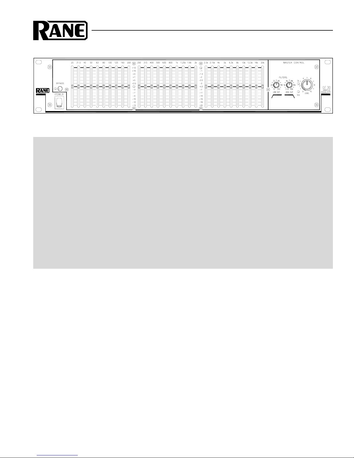
The automatic Bypass function of the GE 30 guarantees
that if power is lost, signal will not be. The Bypass relay
automatically closes the bypass loop when either the POWER
switch is turned off, the line cord is disconnected, or some
other power interruption occurs.
The Rane Model GE 30 is a professional equalization tool,
and as such, it would not be wise for us to recommend that
you “Fiddle with it ‘til it sounds good.” It is because of this
that we offer the following:
MEASUREMENTS
We highly recommend that a real time analyzer be used to
display the combined sound system/room response so
intelligent adjustments may easily be made without a lot of
trial and error. Of course, Rane Corporation builds a very nice
one (the RA 27), at a very reasonable price if you are not
already in possession of one.
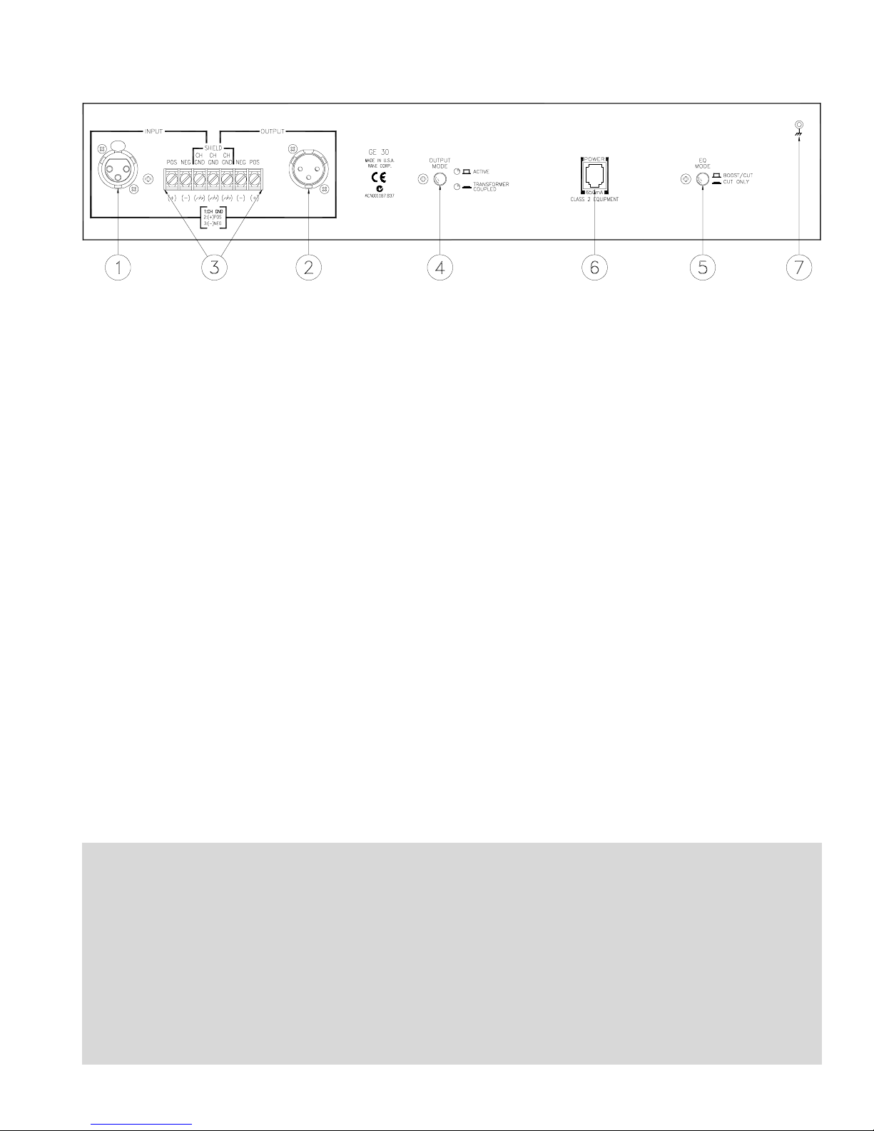
DICE OR SLICE?
Deciding whether the GE 30 should be operated in the
Boost/Cut mode or the Cut-Only mode is a bit of a sticky
problem. For that matter, referring to the Boost/Cut mode
versus the Cut-Only mode is bound to cause some debate
among more than a few readers. There are those that believe it
makes no difference which mode you use, and there are just
as many others who believe that one or the other is the one
and true way to go. This is exactly why the GE 30 offers the
options it does. There are situations where a person of the
Cut-Only persuasion needs to use the “other” type EQ in
certain selected locations. If this is the case, all this person
needs to do is get around behind the rack (hopefully this isn’t
too difficult) and press the EQ MODE selector. There are
others who are not as convinced that one or the other modes is
better, but wish to withhold the decision until the job is
installed and ready for test. Whichever the case, the GE 30
performs its duty better than any other product of either type.
AMPUTATION
Setting the corner frequencies of the High Cut and Low
Cut filters is a function of the type of system and the type of
material that passes through the system. For most installa-
tions, a setting of 40Hz on the low end and 15 to 20kHz on
the high side will be adequate for protecting expensive drivers
and associated equipment. Should the user prefer these filters
have no effect at all, rotating them to their respective high and
low frequency extremes effectively removes them from the
signal path. In all cases, a somewhat careful study should be
made of the overall system requirements so that the individual
1/3-octave controls are not used to correct for an improper
setting of these filters.
ISOLATION
Finally, select the output configuration (Active or Trans-
former) which suits your requirements. In most situations, the
ACTIVE option is probably the best, since it offers the
highest linearity and bandwidth. The degradation caused by
the transformer is very slight, and will not contribute anything
audible to the system if this mode is selected. The differences
are more theoretical than practical.
ENLIGHTENMENT
See Rane Note 101, “Constant-Q Graphic Equalizers” for
an awareness of the benefits of the GE 30’s constant-Q
interpolating filters, available from your dealer, Rane's web
site, or the factory (addresses below).
©Rane Corporation 10802 47th Ave. W., Mukilteo WA 98275-5098 TEL (425)355-6000 FAX (425)347-7757 WEB http://www.rane.com
103121
Table of contents
Other Rane Stereo Equalizer manuals