RANGEFUL Spear 300 PRO User manual

Repeater
Spear 300 PRO, Spear 300 V4G, Spear 300 V3G,
Spear 300 V4G-L, Spear 300 V4G-H, Spear 300 V3G-L,
Spear 1000 PRO, Spear 1000 V4G, Spear 1000 V3G,
Spear 1000 V4G-L, Spear 1000 V4G-H, Spear 1000 V3G-L,
Spear 2000 V4G, Spear 2000 V3G, Spear 2000 V4G-L,
Spear 2000 V4G-H, Spear 2000 V3G-L, Spear 2000 V5G
Installation Manual
Rev. 1.3
EN

1. Product Features ......................................................................................3
2. Safety Information ..................................................................................5
3. Functional elements ..............................................................................6
3.1. Appearance of the Repeater ..............................................................6
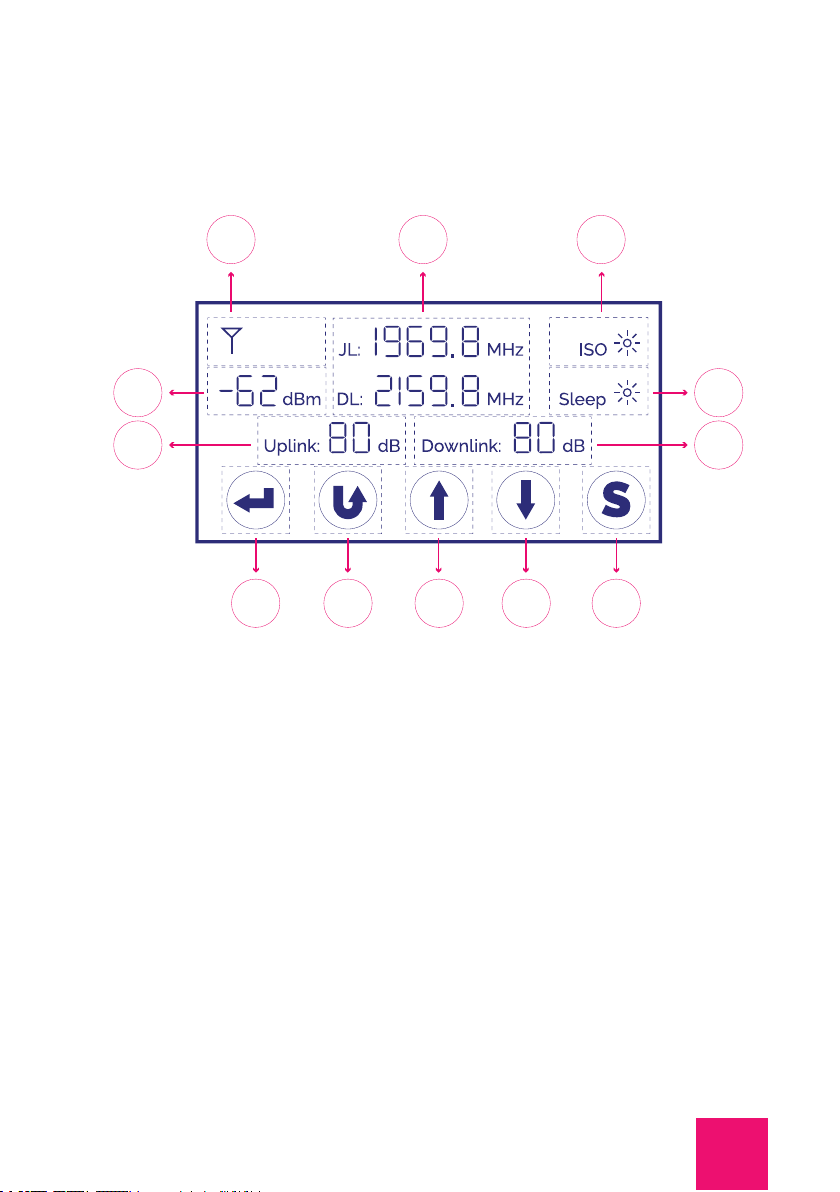
3.2. LED Display ....................................................................................................7
3.2.1. 5-band amplification system .....................................................7
3.2.2. 3-band amplification system .....................................................8
3.2.3. 2-band amplification system ..................................................10
3.3. Alarm LED .....................................................................................................12
3.4. Manual Gain Control (MGC) ................................................................13
3.5. Smart function ............................................................................................13
4. Installation ................................................................................................13
4.1. General conditions ...................................................................................13
4.2. Outdoor antenna installation ............................................................14
4.3. Indoor antenna installation ................................................................19
4.4. Repeater installation ..............................................................................21
4.5. Lightning Surge Protector Installation .......................................23
5. Troubleshooting .....................................................................................24
6. Contact Information .............................................................................25
Content

3
1. Product Features
Coverage area
Spear 300 PRO
Spear 300 V4G
Spear 300 V3G
Spear 300 V4G-L
Spear 300 V4G-H
Spear 300 V3G-L
Spear 1000 PRO
Spear 1000 V4G
Spear 1000 V3G
Spear 1000 V4G-L
Spear 1000 V4G-H
Spear 1000 V3G-L
Spear 2000 V4G
Spear 2000 V3G
Spear 2000 V4G-L
Spear 2000 V4G-H
Spear 2000 V3G-L
Spear 2000 V5G
Coverage area Up to 300m2Up to 1000m2Up to 2000m2
Internal
antennas 1-3 Up to 8 Up to 10
Rangeful Spear is an advanced repeater created for boosting 5
different types of a mobile signal at the same time and works
for all mobile operators in Europe. This repeater is a perfect
option if you use several mobile operators or need to improve
all types of connection. RANGEFUL Spear is a newly designed
signal repeater with smart functions.
Rangeful Spear is the perfect solution for improving the
mobile signal at home, office, restaurant, hotel, apartment
building, warehouse or supermarket, in the quickest time
possible. One repeater covers up to 300, 1000 or 2000 m2
(depends on a repeater modification).

4
Coverage area
Model GSM
calls
900Mhz
4G LTE
internet
800Mhz
GSM
calls
1800Mhz
4G LTE
internet
1800Mhz
3G
internet
900Mhz
4G LTE
internet
2600Mhz
3G
internet
2100Mhz
5G
internet
700Mhz
Spear 300 PRO
Spear 1000 PRO •••••••
Spear 2000 V5G • • • •
Spear 300 V4G
Spear 1000 V4G
Spear 2000 V4G • • • • •
Spear 300 V3G
Spear 1000 V3G
Spear 2000 V3G •••• •
Spear 300 V4G-L
Spear 1000 V4G-L
Spear 2000 V4G-L •••
Spear 300 V4G-H
Spear 1000 V4G-H
Spear 2000 V4G-H • • •
Spear 300 V3G-L
Spear 1000 V3G-L
Spear 2000 V3G-L • • •
Rangeful Spear is compatible with all mobile devices and
supports all services (voice, Internet, SMS, MMS, etc.) provided
by the mobile operators and presented on the site. RANGEFUL
Spear supports all mobile networks in Europe and most
countries of the world.
ATTENTION! Repeater’s signal performance and coverage
area directly depends on the signal performance of the mobile
operator’s base station. Correct installation of the repeater,
antennas and cables is crucial. It is important to understand
that abnormal use of the repeater will lead to its malfunction,
performance deterioration, as well as malfunctions in mobile
operator’s base station. The user is responsible for all possible
problems caused by abnormal use.

5
•
•
•
•
•
•
2. Safety Information
Only qualified personnel are allowed to install the repeater,
cables and antennas.
The antennas and the cables must be connected only when
the repeater power is off to avoid damage to the repeater.
Connection to different power source than those specified
may result in equipment malfunction and damage. If the
restrictions are not followed, fire hazard is possible.
Do not disassemble the repeater, install or remove accessories
by yourself. This may result in equipment malfunction or electric
shock.
Do not install the repeater near the heating equipment to
avoid heating the operating repeater.
Do not cover the repeater, as this may affect the heat
dissipation.

6
1 – Indoor Antenna Connector (N-Female)
2 – Power LED
3 – On / Off Switch
4~8 – Alarm LED 800 / 900 / 1800 / 2100 / 2600 MHz
9 – Power supply input
10 – Smart function LED
11 – Outdoor Antenna Connector (N-Female)
12 – Ground
3. Functional elements
1
2 4 5 6 7 8 10
3 9 11 12
3.1. Appearance of the Repeater

7
1
8 9 10 11 12
25
67
3 4
3.2. LED Display
3.2.1. 5-band amplification system
Applies to models Spear 300 PRO, Spear 1000 PRO
1 – 5 bars of the output signal strength indicator, which show
you the maximum output power of the repeater. Each signal bar
represents 5dB.
4 – Antenna Isolation Detection. When the repeater is first
powered up, the repeater will detect the oscillation
automatically between the outdoor antenna and indoor
antenna.
5 – Uplink Sleep Mode. The uplink of the repeater is in standby
mode when there is no call or data transmission. It will activate
immediately when a call/data session is initiated.
2 – The specific value of the input signal strength measured in
dBm, tells the exact input signal level.
3 – Shows the UL&DL central frequency of the supporting
system.
6 – Shows the UL maximum gain.
7 – Shows the DL maximum gain.

8
3.2.2. 3-band amplification system
1
2
3
4
9 10 11 12 13
5 6 7 8
8 – Selection or confirmation of the settings
LCD screen shows one working frequency at a time, and it will
change automatically each 5 seconds from low frequency to
high frequency.
1 – The line shows the working status of amplification system 1.
– The line shows the working status of amplification system 2.2 – The line shows the working status of amplification system 3.3
Applies to models Spear 300 V4G, Spear 1000 V4G, Spear 2000
V4G, Spear 300 V3G, Spear 1000 V3G, Spear 2000 V3G, Spear
2000 V5G.
9 – Back to the previous page or cancel the settings.
10 – Increase the gain oradjust the center frequency upward.
11 – Decrease the gain or adjust the center frequency downward.
12 – Smart function that repeater could set the gain
automatically to prevent the Alarm. Press this icon to turn ON
or turn OFF this function.

9
4 – 5 bars of the output signal strength indicator, which shows
you the maximum output power of the repeater. Each signal bar
represents 5dB.
8 – Antenna Isolation detection. When you turn on the repeater
for the first time, the repeater automatically detects the
oscillation between the outdoor antenna and the indoor
antenna.
7 – Displays the maximum Upload and Download gain.
6 – Uplink Sleep Mode. The uplink of the repeater is in standby
mode when there is no call or data transmission. It will be
activated immediately when a call or data session is initiated.
5 – The specific value of input signal strength measured in dBm,
which shows us the exact input signal level.
13 – Smart function. The repeater can automatically adjust the
gain to prevent Alarm.
9 – Enter to select or confirm the settings.
10 – Return to the previous page or cancel the settings.
11 – Increase the gain.
12 – Decrease the gain.

10
3.2.3. 2-band amplification system
1
2
7
9 10 11 12 13
8
3 4 5 6
Applies to models Spear 300 V4G-L, Spear 1000 V4G-L, Spear
2000 V4G-L, Spear 300 V4G-H, Spear 1000 V4G-H, Spear 2000
V4G-H, Spear 300 V3G-L, Spear 1000 V3G-L, Spear 2000 V3G-L.
1 – The line shows the working status of amplification system 1.
5 – Show the maximum Upload gain.
7 – Show the status of Uplink Sleep mode and ISO for system1.
11 – Increase the gain.
9 – Enter or confirm the settings for selection.
13 – Smart function. The repeater can automatically adjust the
gain to prevent Alarm.
2 – The line shows the working status of amplification system 2.
6 – Display the Download maximum gain.
8 – Show the status of Uplink Sleep mode and ISO for system2.
12 – Decrease the gain.
10 – Return to the previous page or cancel the settings.
3 – 5 bars of the output signal strength indicator, which shows
you the maximum output power of the repeater. Each signal ba
represents 5dB.
4 – The specific value of input signal strength measured in dBm,
which shows us the exact input signal level.

11
Smart (AGC) and Manual Gain Control (MGC)
Safe Mobile Network option
In order to maintain safe and specific output signal levels, this
repeater has built-in signal oscillation detection circuit to
adjust the gain automatically so as to avoid interference to the
cellular network, it also has color changing LEDs indicating its
environmental status: the Alarm LEDs located on the front of the
unit will change color from green to orange or red, (depending
on the input power level) when the system detects signal
oscillation in the working band or the input signal is beyond
a safe limit.
The repeater also has a Safe Network / MUTE feature that
automatically shuts off the repeater to protect the mobile
network. Users shall make sure the LEDs remain green at
all times for optimum system performance.
The repeater has Manual Gain Control (MGC) feature that enables
manual reduction of the repeater gain via touch screen
if oscillation is detected. You could use the «Smart»
function as well, which will help set to the suitable gain
automatically without any interference to the mobile network.

12
3.3. Alarm LED
Colour Description
Green The repeater works normally.
Green
(Flickering)
Orange
(Flickering)
Red
Orange or Red LED shows signal oscillation or the input signal
being beyond the safe limit.
The repeater works normally. However, the output signal
may exceed the maximum level in the DownLink channel.
In this case, the repeater turns on the automatic gain control, and
the real gain will be less than installed by a manual regulator.
When the repeater is turned on, the amplification system is auto-
tuned for about 40 seconds. If the green indicator blinks for longer
than the specified time, we recommend checking correct
installation of the outdoor antenna (see section 4. Installation).
There may be poor shielding between outdoor and indoor
antennas or close location of the base station of any mobile
operator. If the antennas are installed optimally for a given
location, then it is advisable to manually reduce the DownLink
gain of the repeater and after that set manual UpLink adjustment
to the same or slightly lower value.
The repeater works with medium oscillation. We recommend
checking correct installation of the outdoor antenna (see section
4. Installation).
Attention! It is very important to adjust the gain or ensure
sufficient shielding between the antennas (see section 4.
Installation). The Alarm LED should turn green again otherwise
normal operation of the repeater is not possible.
The repeater can turn off at any time! There was a very strong
(more than 15 dB)
excess of the sum «signal level from the outdoor antenna +
repeater gain» over the maximum output power of the repeater.
Attention! It is very important to adjust the gain or ensure
sufficient shielding between the antennas (see section 4.
Installation). The Alarm LED should turn green again otherwise
normal operation of the repeater is not possible.

Press « » icon and keep on till you reach the uplink gain (the
uplink gain figure is flickering), then press « » to decrease the
gain as per the request, you can also press « » to increase the
gain once the setting is not proper. Please do remember to press
« » again to confirm the settings after setting to the right
value.
The Smart function means that the repeater can set the gain
automatically. Users could press « » to turn ON or turn OFF
this function.
Remark: When the Smart function is on, users can not
set the gain manually. If you need to set the gain by hand,
please first turn OFF the Smart function and then follow
the instruction of MGC setting.
13
The same operation isfor setting the DownLink gain.
•
•
3.4. Manual Gain Control (MGC)
3.5. Smart function
4.1. General conditions
4. Installation
First, assemble the mobile signal amplification system. Use the
following additional equipment:
An outdoor antenna that will provide communication between
he repeater and base stations of mobile operator.
An indoor antenna or several antennas that will provide
communication between the repeater and mobile devices.

14
•
4.2. Outdoor antenna installation
Coaxial cable (50 Ohm) and connectors (N-type or SMA
according to the antennas used) for connecting antennas to the
repeater.
It is recommended to install the outdoor antenna free from
visible obstacles to signal transmission. The optimal antenna
performance can be achieved by attaching it to a mast or
bracket and pointing it towards the operator base station.
To understand the self-oscillation process you can take
a microphone and a loudspeaker and bring them close to each
other. You will hear a very loud noise.
The signal strength from the outdoor antenna directly affects
the efficiency of the indoor coverage. That’s why it is very
important to choose the good outdoor antenna location in order
to get the best signal.
The repeater is a highly sensitive bi-directional amplifier of
a mobile signal, therefore it is necessary that the outdoor
and indoor antennas are well isolated from each other to
avoid self-oscillation of the repeater. The minimum distance
between the outdoor and indoor antenna is 10m. If isolation
can’t be achieved due to limited distance, the roof of the
building, concrete or brick walls or any other barriers can be
used between antennas to increase isolation. There is also
highly recommend 3-4m vertical distance between antennas.
In addition, splitters, couplers, antenna amplifiers and boosters
may be needed to create a mobile signal amplification
system. All this equipment you can find on our website
www.rangeful.com

15
A
B
C
D
E
If you don’t know the exact location of your operator’s base
station, go through the antenna aiming process for getting the
best result. To aim the antenna correctly, follow the steps below:
1. As shown from the picture above, testing the mobile operator
signal quality from point A to E, and select the best place that
displays maximum bar signals.
2. Install the outdoor antenna on the point with best signal,
install the cables, repeater, indoor antenna and switch on the
system.

16
•
•
•
•
•
•
3. A person on the roof aims the antenna in a certain direction.
The other person inside waits for 1 minute and checks
the signal level on the phone.
4. Slightly rotate the antenna for 30-45 degrees. The other
person inside waits one more minute and checks signal level
again.
5. Repeat the process until the best antenna position is found.
The lower dB parameter gives better system performance
results. For example, «-89» is better than «-95».
6. Fix the antenna in the position with the best signal result.
When installing an outdoor antenna, the following guidelines
should be observed:
Do not install it in rain or thunderstorm.
Follow the antenna assembly and installation instructions
carefully.
Protect all connectors from water and moisture.
Install it as far as possible from metal structures, high voltage
cables and transformers to avoid radio interference.
If possible, direct the antenna into an open area and avoid
directing it towards nearby obstacles (forest, building, hills, etc.).
Avoid installing an outdoor antenna near the mobile operator’s
base station.

17
ATTENTION!
•
•
•
The outdoor panel antenna installation example
The outdoor Yagi antenna installation example
After installing the outdoor antenna, it is necessary to carefully
check the cables connection, since is affects the signal quality.
Avoid sharp bends and deformations.
Give waterproof treatment to outdoor connection parts.

18
1
2
6
7
8
4
5
3
Сorrect and incorrect installation of an outdoor
antenna
1. Do not install the antenna on the roof slope.
6. The outdoor antenna is installed on the chimney. This
allows you to optimally tune it to the base stations. If the roof
is covered with metal panels, it creates an additional shield
between the outdoor and indoor antenna.
7. The antenna is installed on the mast. This allows to raise the
antenna higher and get a better input signal.
8. The antenna is installed on the wall of the building. This is the
quickest and easiest way to install the antenna.
3. Do not point the antenna towards the sky.
2. Wrong antenna direction.
5. The outdoor antenna must be securely mounted and pointed
towards the base station.
4. Installing an outdoor antenna inside will significantly reduce
signal performance.

19
4.3. Indoor antenna installation
•
•
Select indoor antennas according to the site conditions. Indoor
antennas are needed for the repeater to interact with mobile
devices inside the premises. Indoor antennas allow the
repeater to create a local area for mobile communication.
Single indoor antenna is used in simple installations. It is
connected directly to the repeater. This antenna distributes all
the energy of the mobile signal that comes to it from the
repeater.
Omni antenna (Indoor omni ceiling antenna or whip antenna),
is suitable to be installed in the center and radiate all directions.
It is recommended to use a directional panel antenna when
the coverage shape is long and narrow (corridors, long row of
houses in two sides, tunnels or elevators or rural open space).
Omni or Directional antennas can be used:

20
•
•
•
•
The indoor antenna’s coverage area and the range are
determined by many factors.
Repeaters can use more than one indoor antenna especially
repeaters equal to or over 20dBm. A 20dBm repeater can be
connected with up to 6-8 antennas to equally send the signals
to larger areas. Please consult professional engineers about
the solution if you want to connect more than one antenna.
The most significant are:
Antenna radiation pattern.
Antenna location.
The actual output power of the repeater at the frequencies of
the operator to be amplified.
Construction materials of the building and / or other objects in
the repeater coverage area.
This manual suits for next models
17
Table of contents
Languages:
Other RANGEFUL Repeater manuals