IV
Contents
1
Unpacking and Checking...........................................................................................................- 1 -
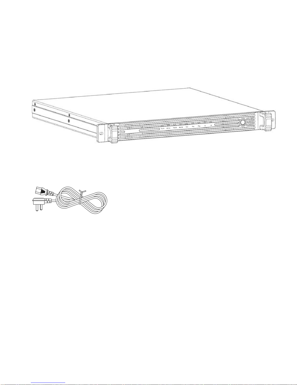
1.1
Accessories........................................................................................................................ - 1 -
2
Overview ....................................................................................................................................- 3 -
2.1
Power Switch......................................................................................................................- 5 -
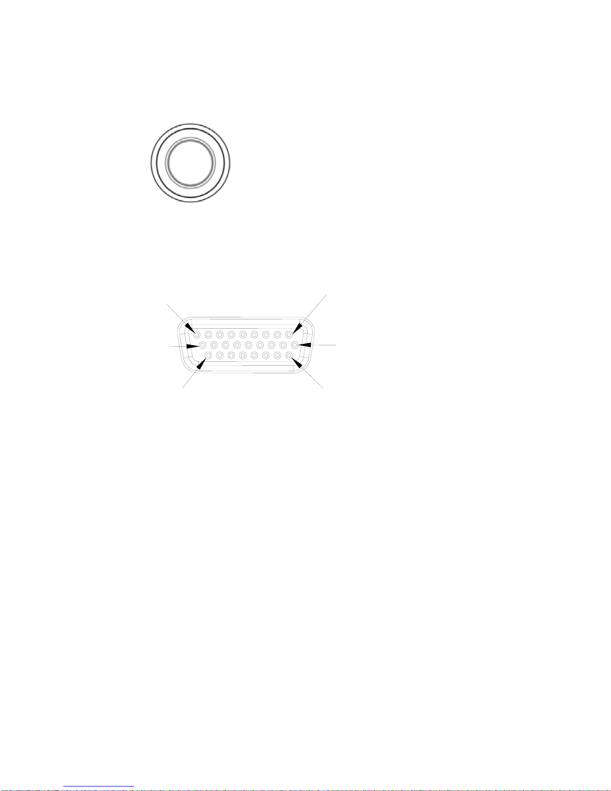
2.2
ACCY Interface...................................................................................................................- 5 -
2.3
Panel LED Indicator ...........................................................................................................- 8 -
3
Basic Operation..........................................................................................................................- 9 -
3.1
Power on /off Repeater ......................................................................................................- 9 -
3.2
Voice and Data Transmission ............................................................................................- 9 -
3.3
IP Interface.......................................................................................................................- 10 -
3.4
Emergency Alarm.............................................................................................................- 10 -
3.5
Programming Software..................................................................................................... - 10 -
3.6
IP Connect* ......................................................................................................................- 16 -
4
Trouble shooting ......................................................................................................................- 16 -
5
Parameters...............................................................................................................................- 17 -