2
INSTALLATION MUST BE MADE BY A LICENSED/QUALIFIED COMMERCIAL GAS EQUIPMENT
SERVICE AGENCY/COMPANY
The input rating on your appliance is for elevations up to 2,000 feet. For elevations above 2,000 feet the rating must
be reduced to 4% for each 1,000 feet above sea level.
INSTALLATION, OPERATION & MAINTENANCE
(1) PRE-INSTALLATION - SPACE AND GAS CONNECTIONS
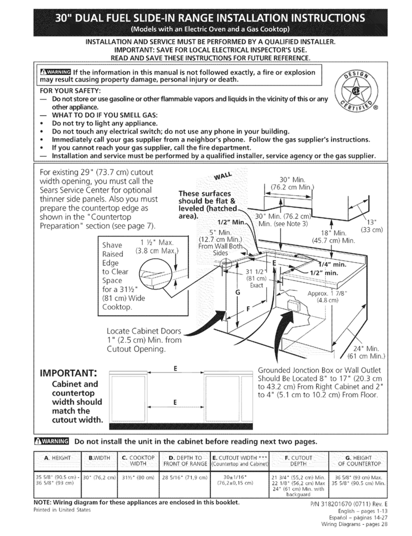
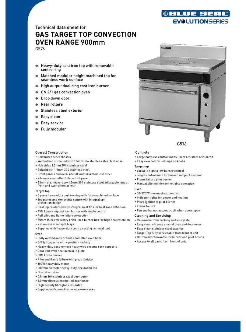
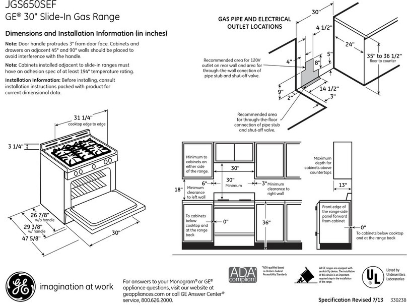
(a) The area around the appliance must be kept free and clear from combustibles. The area in front of
and above the appliance must be clear to avoid any obstruction to the flow of combustion and ventilation air. Means
must be provided for adequate air supply and adequate clearance from air openings into the combustion chamber.
(b) Adequate clearance must be provided in front and sides of appliance for servicing and proper
operation.
(c) Your appliance is designed for installation in a combustible or non-combustible location. If the
appliance is installed in a combustible location, the following clearances must be observed: 12" to sides and 12" to
back. If installed in a non-combustible location, the clearances are: 1" sides and 6" back.
(2) INSTALLATION
(a) The gas pressure regulator supplied with the appliance must be installed on the appliance prior to
connection to the gas supply lines. The outlet pressure setting is 5" water column on natural gas and 10" water column
on propane gas (LP Gas).
(b) Connect the appliance to a gas supply line having a 3/4 inch iron pipe size or larger. If a flexible
connector is used it must be 3/4" I.D. (Domestic range connector will not permit proper operation). A gas shutoff
valve must be installed in the gas supply line ahead of the appliance for future service. Use pipe sealant on all joints.
Sealant must be resistant to the action of LP gas. A 1/8" pressure tap is provided on the gas manifold for checking the
gas pressure. Always check pressure with all burners on and adjacent equipment operating.
(c) Level the appliance by adjusting feet at the bottom of the legs. Leveling is important for proper
operation and combustion. If a level is not available, use pan of water.
(d) To check for leaks, use a soap and water solution. DO NOT USE OPEN FLAME.
(e) The appliance and its individual shutoff valve must be disconnected from the gas supply piping
system during any pressure testing of the system at test pressures in excess of 1/2 psig (3.45kPa).
(f) The appliance must be isolated from the gas supply piping system by closing its individual manual
shutoff valve during any pressure testing of the system at test pressure equal to or less than 1/2 psig (3.45kPa).
(3) OPERATION
(a) Turn off all burners and pilot valves. Wait 5 minutes.
(b) Turn on pilot valves and light all pilots.
(c) Adjust pilot flame by turning the pilot valve screw clockwise or counterclockwise.
(4) MAINTENANCE
(a) CLEANING Appliance must be cool before cleaning.
Top grates, burners, and wok rings should be cleaned periodically by wire brushing or washing in hot water
and detergent.
The stainless steel front and trim should be cleaned with mild soap or detergent or with a liquid cleanser
especially for use on stainless steel. Never attempt to clean stainless steel with steel wool, abrasive cloths or powders.
The drip tray should be emptied as needed and cleaned with hot water and soap or detergent.
(5) SERVICE
No immediate need for service is anticipated. Thereafter service needs vary with frequency of use. Twelve
hours per day, seven days per week is considered heavy use and appliance should be serviced every ninety days. For
lesser use, consider service every six months.
