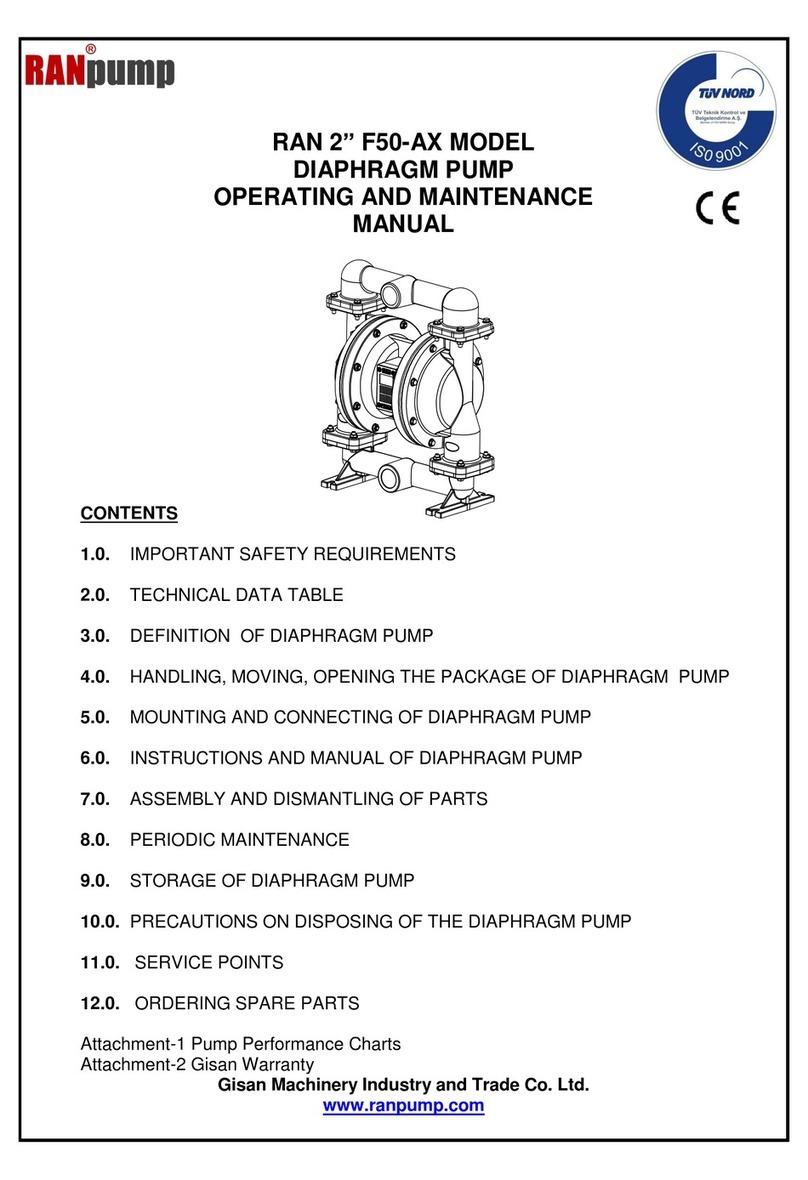
Ranpump B15-AX Operating instructions

RAN 1/2” B15-AX MODEL
DIAPHRAGM PUMP
OPERATING AND MAINTENANCE
MANUAL
CONTENTS
1.0. IMPORTANT SAFETY REQUIREMENTS
2.0. TECHNICAL DATA TABLE
3.0. DEFINITION OF DIAPHRAGM PUMP
4.0. HANDLING, MOVING, OPENING PACKAGE OF DIAPHRAGM PUMP
5.0. MOUNTING AND CONNECTING OF DIAPHRAGM PUMP
6.0. INSTRUCTIONS AND MANUAL OF DIAPHRAGM PUMP
7.0. ASSEMBLY AND DISMANTLING OF PARTS
8.0. PERIODIC MAINTENANCE
9.0. STORAGE OF DIAPHRAGM PUMP
10.0. PRECAUTIONS ON DISPOSING OF THE DIAPHRAGM PUMP
11.0. SERVICE POINTS
12.0. ORDERING SPARE PARTS
Attachment-1 Pump Performance Charts
Attachment-2 Gisan Warranty
Gisan Machinery Industry and Trade Co. Ltd.
www.ranpump.com

2
1.0. IMPORTANT SAFETY REQUIREMENTS
a-
This equipment is for professional use only. Observe all warnings. Read and
understand all instruction manuals, warning labels, and tags before you operate the
equipment.
b-
CAUTION: This manual contains important instructions and safety cautions on
diaphragm pumps. Read and understand all of it before first use of the pump.
Manufacturer is not responsible for damages and injuries caused by
inappropriate usage of the pump.
c-
Diaphragm pump usage is limited to within the area defined in this manual. Refer to
GİSAN for any further questions.
d-
Never let unqualified / unauthorized people operate a diaphragm pump.
e-
Never alter or modify any part of this equipment; doing so could cause it to
malfunction. Use only genuine RAN® Pump parts and accessories.
f-
Illuminate the environment thoroughly for proper usage and maintenance of the
equipment.
g-
Do not make changes to the pump that may affect its working systems.
h-
Pump maintenance and repair should only be carried out by qualified personnel.
i-
Do not surpass the strength of minimum system compound.
j-
Learn hazards or potential dangers of your fluid.
k-
Choose the wet pump parts’ material resistant to your fluids. Refer to the Proper
Material-Fluid Chart or your supplier for further information.
l-
Use an approved container for the hazardous media.
m-
Do not pull the pump by the hoses.
n-
Do not let the hoses twist.
o-
Make sure that hose connections to the pump are tight to avoid air suction.
p-
Do not lift or move the pump while it is pressurised.
r-
If you are working with flammable or toxic fluids, be sure the system is properly
ventilated for your type of installation. You must vent the exhaust to a safe place,
away from people, animals, food, and all sources of ignition when pumping
flammable or hazardous fluids. Note that when there is a tear on the diaphragm, the
media in the pump will be exhausted together with the air. Refer to the Figure 9- Air
Exhaust.
s-
Diaphragm pumps described in this technical file are sold only as a pump unit. A
control unit is not supplied with the pump. The user/operator is responsible for
installing a suitable control system if needed.
t-
Tightly connect the proper hose for your media to one end of the pump and the other
to the tank where the media will be stored.

3
WARNING !
Always wear appropriate clothing and equipment, such as
eye protection and breathing apparatus to protect yourself.
WARNING !
Improper handling, splashing in the eyes, ingestion, or bodily
contamination of hazardous fluids or inhaling toxic vapors can
cause extremely serious injury or death. Observe all the
following precautions when handling known or potentially
hazardous fluids.
WARNING !
Altering or modifying any part of this equipment, using eroded
or damaged spare parts, or using this pump for inappropriate
media may cause the parts to break or be damaged. Thus, the
media inside the pump may spill or squirt onto people in the
vicinity and sensitive areas, such as eyes. Moreover, it may
cause a fire, blast, or physical damage.Use only genuine RAN™
parts and accessories.
WARNING !
Never use 1,1,1-trichloroethane, methylene cloride, other
halogenated hydrocarbon solvents or fluids containing such
solvents in aluminum pumps. Such use could result in a
serious chemical reaction, with the possibility of explosion,
which could cause death, serious injury, and/or substantial
property damage. Consult your fluid suppliers to ensure that
the fluids used are compatible with aluminum parts.
WARNING !
Running the pump with hot liquids may cause the surface of
the pump to heat up above 80 Co. Under these conditions, it
is pump owner’s responsibility to place a warning for the
operator not to touch the pump without appropriate
protective equipment to reduce the risk of severe burns.
1.1. Warnıng symbols on dıaphragm pump
No
Warning
Location on
pump
Instruction
1
Pump Name Plate
Exhaust Cover
Pump Data
1.2. Conformity to eu directives and standards
All the diaphragm pumps produced comply with the below listed EC directives and standards.
2006/42/EC Safety of Machinery
EN ISO 12100 Safety of machinery -- General principles for design-
Risk assessment and risk reduction
DIN EN 809 Pumps and pump units for liquids - Common safety requirements
EN ISO 4414Pneumatic fluid power -- General rules and safety requirements for systems and their
components

4
2.0. DIAPHRAGM PUMP TECHNICAL DATA
1/2 ’’ ALUMINIUM PUMP
Description
Unit
Value
Pump Type
Inch
1/2” Aluminium
Max. fluid working pressure
Bar, Psi
7 (0.7 Mpa, 105 Psi)
Air feeding pressure range
Bar
1.0 to 7
(0.10 - 0.7 Mpa, 105 Psi)
Max. Air consumption
m3/minute
0.5
Fluid per cycle
lt/cycle
0.138
Max. Head (for water viscosity)
m
70
Max. Suction depth
m
3
Max. Particle allowance
mm
1,5
Noise power level (at 5 bar)
dBA
74
Max. Capacity
lt/minute
60
Max. Cycle per minute
Cycles/minute
432
Max. Fluid temperature
⁰C
80 ⁰C
Min. environment temp.
⁰C
5 ⁰C
Max. environment temp.
⁰C
40 ⁰C
Air inlet
Inch
1/4”
Air outlet
Inch
1/4”
Fluid inlet
Inch
1/2”
Fluid outlet
Inch
1/2”
Pump housing material
Aluminium
Pump diaphragm material
Weight
kg
3,5
Package Dimensions / Packaging Weight
cm / g
16x21x32 / 600
2.1. Dıaphragm runnıng temperature data
Diaphragm
Material
Temperature limits
BUNA-N
-12,2 ⁰C
65,6 ⁰C
PTFE (teflon)
4 ⁰C
104,4 ⁰C
Santoprene
-28,9 ⁰C
104,4 ⁰C
Polyurethane
-12,2 ⁰C
65,6 ⁰C
VİTON
-40 ⁰C
176,7 ⁰C
Neoprene
-17,8 ⁰C
93,3 ⁰C
EPDM
-51,1 ⁰C
137,8 ⁰C
3.0. DIAPHRAGM PUMP DEFINITION
A diaphragm pump works with compressed air coming from a compressor. Pump working principle
is shown in the illustration below.
There are two valves distributing air in the pump. Outer valve is distributing the air to the
diaphragms. Inner air valve is rotating the outer valve.
Running a pump fast does not always mean working it most productively. If a pump works at
highest capacity continuously, it will have diaphragm and valve problems sooner. It is
advised to choose a higher capacity pump and it should not be used at maximum pressure
for long periods.
Diaphragm pump is mounted on the ground or on a tripod from its legs with bolts.
Air operated diaphragm pumps are suitable for transferring fluids up to 50,000 cP viscosity.

5
RIGHT STROKE
Compressed air is directed to
the back side of diaphragm B
by the air valve. The
compressed air moves the
diaphragm away from the
center block. The compressed
air pushes the liquid column
separated by elastomeric
diaphragm, forcing the fluid
through the fluid outlet. At the
same time, the opposite
diaphragm is pulled in by the
shaft connected to the
pressurized diaphragm. So,
diaphragm A is on its suction
stroke: the air behind
diaphragm A is forced out to
the atmosphere through the
exhaust port of the pump. The
movement of diaphragm B
away from the center block of
the pump creates a vacuum
within chamber A. The vacuum
force sucks the fluid into the
inlet manifold forcing the inlet
valve ball off its seat. The fluid
is free to move past the inlet
valve ball and fill liquid
chamber A.
MIDDLE STROKE
When the pressurized
diaphragm, diaphragm B,
reaches the limit of its
discharge stroke, the air valve
redirects compressed air to
the back side of diaphragm A.
The pressurized air forces
diaphragm A away from the
center block while, at the
same time, the connected
shaft pulls diaphragm B to the
center block. Diaphragm A is
now on its discharge stroke.
Diaphragm A forces the inlet
valve ball onto its seat due to
the hydraulic forces
developed in the liquid
chamber and manifold of the
pump. These same hydraulic
forces lift the discharge valve
ball off its seat, while the
opposite discharge valve ball
is forced onto its seat, forcing
the fluid to flow through the
pump discharge. The
movement of diaphragm B
toward the center block of the
pump creates a vacuum
within liquid chamber B.
Atmospheric pressure forces
the fluid into the inlet manifold
of the pump. The inlet valve
ball is forced off its seat
allowing the fluid being
pumped to fill the liquid
chamber.
LEFT STROKE
At completion of the stroke,
the air valve again redirects
air to the back side of
diaphragm B, which starts
diaphragm A on its exhaust
stroke. As the pump
reaches its original starting
point, each diaphragm has
gone through one exhaust
and one discharge stroke.
This constitutes one
complete pumping cycle.
The pump may take several
cycles to completely prime
depending on the conditions
of the application

6
3.1.Diaphragm pump has the name plate shown on diagram 1
Figure 1- Pump Name Plate
3.2. Diaphragm pump coding system
X X –X X
DIAPHRAGM
MATERIAL
Inlet
outlet
Body materıal
Dıaphragm
materıal
B = 1/2”
A = Aluminium
0 = Buna- N
C = 3/4”
P =
Polypropylene
1 = PTFE (teflon)
BODY MATERIAL
D = 1”
C = Cast Iron
S = Santoprene
INLET OUTLET
E = 1 ½”
S= Stainless
Steel
F = 2”
G = 3”
3.3. Main parts of diaphragm pump.
Figure 2 - Diaphragm pump main parts.
No
Description
1
Center section
2
Valve
3
Diaphragm
4
Body
5
Manifold
6
Leg

7
3.4. Diaphragm pump main dimensions.
Figure 3 –Diaphragm pump main dimensions.
4.0. HANDLING, MOVING, OPENING THE PACKAGE OF DIAPHRAGM PUMP
Handle the pump by manifolds to move. Pumps are packed in carton boxes.
Figure 4 –Pump package.
Pump package must be at least 130 grams and produced from the kraft carton. It must be fully
covered with packaging separators.

8
5.0. MOUNTING AND CONNECTION OF DIAPHRAGM PUMP
A typical setup configuration is shown in figure 7. Further information and consultation on pump
setup can be provided by your Ran Pump distributor.
ALWAYS USE ORIGINAL RAN PUMP PARTS AND ACCESSORIES. FAILURE TO DO SO
WILL INVALIDATE THE GUARANTEE
Pump should fixed firmly to the ground or platform and should be fitted in a perpendicular
position as shown in Figure 5. Never place the pump at an angle, lying on the ground or upside
down. The pump will not run correctly and check valves and diaphragms will wear out very
quickly due to constant dry running.
When installing the pump ensure that it is balanced correctly when using a lifting device.(Figure
5)
Figure 5 –Diaphragm Pump Mounting Position
5.1. Mounting pump
Keep the points below in mind when choosing the pump mounting place.
-Easy access when operating or maintaining.
-(Air valves, inlet and outlet manifolds of air and fluid, etc.)
-Pump weight relative to the ground/platform.
-Vibration emission to the ground and other equipment.
Figure 6 –Minimum space requirement around the diaphragm pump.

9
5.2. Tightening the bolts before first use
After you unpack the pump, and before you use it for the first time, check and tighten external
fasteners. Tighten the fluid cover screws first, then the manifold screws. (Refer to Figure 7for torque
figures). This keeps the manifolds from interfering with tightening the fluid covers.
After using a day check the fasteners again and adjust the torque if necessary. Recommended
frequency for tightening fasteners varies with pump usage, a general guideline is to retighten fasteners
everytwo months. (Refer to Figure 7 for torque figures).
Exhaust gas may contain dirtying materials. To avoid polluting your fluid container, place the exhaust
hose away from it. (Refer to Exhaust Air section. Item 5.7) Fasten the pump foot tightly to the platform
with bolts. Always use seals (teflon, etc) when connecting with bolts.
Pump
Type
Part
Bolt
Torque
N.m
RAN 1/2’’
M
Air valve
M6
6,8 –7,6
Body
M6
7 - 8
Manifold
M6
6 - 7
Diaphragm bolt
M8
17 - 20
Figure 7 –Pump parts tightening torque table.
5.3. Compressed aır connection
A bleed-type master air valve is required in your system to relieve air trapped between this valve and
the pump. Trapped air can cause the pump to cycle unexpectedly, which could result in serious injury,
including splashing in the eyes or on the skin, injury from moving parts, or contamination from
hazardous fluids. See Fig. 7.
1- Refer to the Figure 7 for the connection scheme. Fix these accessories to the wall or to a
bracket. The air line feeding the accessories must be grounded.
2- Install a filter - regulator to the air line. Use a 5μ (micron) air filter. The pressure of
liquid outlet should be level to air regulator’s. Air line filter is for cleaning the dust and
humidity from the air of the compressor.
3- Install an air discharge valve below the pump inlet air line. It will be used to discharge
remaining air in the pump. Install the main air valve above all air line accessories and use it
to cut off the main air from the accessories while maintaining or cleaning.
4- Use a flexible air hose between the pump air inlet and accessories at minimum 3/8
inch (9.5 mm) inner diameter and not longer than 2 meters. For a hose longer than 2 m,
enlarge the inner diameter respectively.
5.4 Important points while connecting compressed air to diaphragm pump
1- Pay attention not to let any object enter the pump before connecting to compressed air
system.
2- Before connecting to compressed air system, remove all particles from the system using
blown air.
3- If the hose connections are sealed with teflon tape, wind the tape a few screw teeth before
the end of the connecting accessory to avoid any teflon pieces entering the system.
4- When using screw connections, note not to mis-screw or apply excessive power on the
screws.

10
Figure 8a - Typical installation scheme
5.5. Fluıd lıne
5.5.1. Fluid suction line
1- Use a conductive hose or pipe.
2- Screw fluid fitting into the pump inlet
tightly.
3- If the inlet fluid pressure is more than
25% of the outlet working pressure, ball
check valves will not close fast enough,
result will be inefficient pump operation.
4- At inlet fluid pressures greater than 15
psi (0.1MPa, 1 bar), diaphragm life will be
shortened.
5.5.2. Fluid discharge line
1- Use a conductive fluid hose or pipe. The
pump fluid outlet is 1/2”. (f).
2- Screw the fluid fitting into the pump
outlet securely.
3- Install a fluid drain valve at the pump
outlet.
4- Install a fluid shut off valve at the fluid
outlet.
Figure 8b –Example of barrel installation
CAUTION !
Do not overtighten the fittings to
the pump. Otherwise you can
damage the pump.

11
Figure 8c - Bypass line installation
Caution. It is advisable to install a pressure relief system (bypass line)to
relieve high levels of pressure that may occur if the pump is pressurised for a
long period when not operating.
On some uncontrolled systems the back pressure generated from a closed
outlet hose can cause the pump to stop or even reverse operation. In this case
a pressure relief system (bypass line) MUST be installed.
When using long pipelines, that may be pumping cold fluid with hose placed
in a warmer area such as underground tank or buried underground, in
sunshine or near other heat sources the hose may be affected by thermal
expansion of the liquid, causing an increase in pressure. Hose rupture may
result. In this case, a pressure relief system (bypass line) must be installed.

12
5.6 Ground the pump as shown below
5.6.1. For the pump: Use a conductor (for grounding) with a cross-section of at least 1.5 mm2.
Connect the conductor to the pump’s leg as shown on Fig. 9, and the other end to the grounding
line.
5.6.2. For air or fluid hoses: Use hoses that are at most 150 m long and that can be grounded.
Figure 9- Pump grounding
5.7. Ventilating exhaust air
You must vent the exhaust to a safe place, away from people, animals, food, and all sources of
ignition when pumping flammable or hazardous fluids. Note that when there is a tear on the
diaphragm, the media in the pump will be exhausted together with the air. To avoid this, exhaust
the gas away from the operation environment. The pump exhaust air may contain contaminants.
Ventilate to a remote area if the contaminants could affect your process.
When transferring hazardous fluids, follow the steps below:
Remove the muffler from the exhaust port.
Install a conductive and grounded air exhaust hose with the minimum diameter of 1/2 inch 13 mm ID.
If a hose longer than 4.5 m is required, use a larger diameter hose. Avoid bending the hose sharply.
Place a suitable conductive container at the end of exhaust hose to catch the fluid in case diaphragm
ruptures.
Figure 10- Ventilating exhaust air
CAUTION !
To reduce the risk of static sparking, ground the
pump and all other equipment used or located in
the pumping area.

13
WARNING !
When you are transferring hazardous fluids or the pump
temperature is over 60C, operator has to make precautions to
drain the fluid.
WARNING !
FIRE AND EXPLOSION HAZARD
If you are working with flammable fluids, be sure to take
precautions around the pump while cooling it. You must vent the
exhaust to a safe place
WARNING !
Diaphragm pumps are sold as pump unit only. Installing a
control device (if needed) is responsibility of the operator.
If the power supply of the pump (compressor) is stopped, the air
inlet to the pump must be cut off immediately. Otherwise when
compressor restarts, pump may start unexpectedly.
Manual operation: If the power supply of the pump
(compressor) is stopped, operator must cut off the air feed to
the pump manually. The operator must be informed and warned
about this.
Automatic operation: If the power supply of the pump
(compressor) is stopped, control unit must cut off the air feed to
the pump automatically. Installing this system is the
responsibility of the operator or the owner.
IMPORTANT NOTE :
If the diaphragm pump is submerged in water it is important that
the fluid will not enter the air exhaust system. To ensure this
please use the special exhaust cover with suitable attached hose
with hose exit not submerged in fluid.

14
6.0. PUMP OPERATION INSTRUCTIONS
IMPORTANT NOTE
The pump has a variable temperature resistance to the transferred
fluid. The temperature resistance of the diaphragm, balls, and ball
seats defines the temperature resistance of the pump.
6.1. Flush the pump before use.
Pump is tested with water. Flush the pump with a proper solvent before use if your fluid is affected by
water. Follow the instructions in Starting and Adjusting the Pump.
6.2 Starting and adjusting the pump
1- Check pump grounding before use.
2- Check fittings to be sure they are tight. Use a compatible liquid thread sealant (teflon, etc.) on male
threads. Tighten fluid inlet and outlet fittings securely.
3- Submerge the suction hose in the fluid.
Note: If the inlet fluid pressure is more than 25% of the outlet working pressure, ball check valves
will not close fast enough, result will be inefficient pump operation.
4- Place discharge hose in a suitable container.
5- Turn off the fluid drainage valve.
6- Turn the air regulator knob three quarters of a cycle clockwise, and open all bleed-type master air
valves.
7- Increase the air pressure slowly using the air regulator untill the pump primes. Set air regulator to 2
bar pressure. Operate the pump slowly until it is fully loaded.
8- Working with thick fluids, operate the pump very slowly until it is fully loaded.
9- Pump is tested with water. If you need a clean pump in your process, flush the pump with suitable
fluid until it is fully clean. Then place the suction hose in the fluid container to be pumped.
WARNING !
Do not run the pump before you make sure all the
adjustments are OK.
6.3. Stopping the pump
Cut off the air when the pump is not working.
6.4. Pressure relief procedure
1- Shut off the air valve. To relieve the air between the air valve and the pump, use the Air Pressure
Discharge Valve.
2- Shut off the Fluid Valve. Place a container under the Fluid Pressure Discharge Valve and open the
valve. Take the Fluid Discharge Hose off.
3- To discharge the fluid inside the pump follow the instructions below.
a-Put on proper protection equipment for the fluid you are pumping. Shut off the valve on the fluid inlet
hose if installed. Have a container ready to catch the drainage. Pull out the fluid inlet hose from the
manifold. Unravel it from the ground if fixed.
b- Before pulling out the hose from the pump put a container under the pump. Pull it out slowly and
carefully.
WARNING ! PRESSURIZED EQUIPMENT HAZARD
The equipment stays pressurized until pressure is manually relieved.
To reduce the risk of serious injury from pressurized fluid,
accidental spray from the gun or splashing fluid, follow Pressure
Relief Procedure whenever you
need to relieve pressure
stop pumping check, clean or service any system equipment

15
7.0 ASSEMBLY AND DISMANTLING OF PARTS
WARNING:
Before service and maintenance always relieve the air and fluid
pressure.
This explanation refers to figures defined in part (7.0) line (12) fig. 14.
7.1. Ball check valve repair
Tools required
- Torque wrench
- 5 mm allen key
- 10 mm wrench
7.1.1 Dismantling
NOTE: To ensure proper seating, you should change the seats with
the ball check valves.
1- Relieve the pressure in pump. Remove the hoses.
2- Dismount the pump from the ground.
3- Remove the upper elbow manifolds and bolts fixing them to the
main body using 5 mm allen key and 10 mm wrench.
4- Remove the manifold o-rings, ball cages, valve balls and ball seats
from the pump cover.
5- Turn the pump over. Remove inlet manifolds. Remove the o-rings,
ball cages and valve balls from the pump.
7.1.2.Re-assembly
1- Clean all the parts and inspect for wear.
2- You can re-assemble the pump in reverse order. Check valve balls
must be placed on the cages using their own weight.
3- If assembled differently, the pump will not work.
4- Tighten the screws applying the proper torque from the torque
chart. (Fig. 6)
7.2. Changing diaphragm
Tools Required
- Lithium-base grease (non-freezing silicone grease)
- 5 mm allen key
- 10 mm wrench
- 13 mm wrench x 2 Figure 11- check valve repair
- torque wrench
- Philips-head screwdriver
WARNING!
Transferred liquid enters air chamber of pump
when the diaphragm ruptures. Liquid can damage
the pilot valve o-rings and the air valve o-rings due
to its chemical behaviour. For this reason you must
check and replace (if needed) the o-rings while
changing the diaphragm. If only the diaphragm is
changed that will not constitute good maintenance
and you can have a pump problem soon.

16
1- Relieve the pressure.
2- Remove the manifolds and disassemble the ball check valves as explained in Ball Check Valve
Repair section.
3- Using a 5mm allen key remove the bolts connecting fluid chamber body sections from the centre
section. Remove the fluid chamber body sections.
4- Using a13mm socket wrench on each side simultaneously loosen both the diaphragm bolts.
5- Remove O-Ring, diaphragm and back- up diaphragm( if pump has Teflon® diaphragms installed)
6- Remove the other diaphragm shaft bolt from the pump centre section. Remove the shaft. Remove
the remaining diaphragm(s)
7- Remove the cover that is holding the pilot shaft and diaphragm shaft.
8- Check the diaphragm shaft, O-Rings and bearings for wear and abrasion.
9- Clean all parts and inspect for wear or damage.
10-There is text on the air side of the diaphragm.
11-Grease the diaphragm shaft lightly.
12-In the Teflon Diaphragmed pumps, Rubber diaphragm is protected by putting a teflon
diaphragm to the side that is in contact with the fluid.
13-Re-assemble the parts in the reverse order.
14-Tighten the screws applying the proper torque from the torque chart. (Fig. 7)
Figure 12 - Diaphragm Change
7.3 Air valve repair
Tools Required
- Torque wrench
- 5 mm allen key
- Lithium-base grease (non-freezing silicone grease)
NOTE: Hold the air valve vertical position if the core is sliding with its own weight in the valve body,
valve z-rings need to be changed.
1- Relieve the pressure.
2- Unscrew the bolts fixing the valve.
3- Remove the two valve covers and then push the core out using a finger and remove from the other
side.
4- Ensure that you do not damage the o-rings when inserting the valve core.
5- Insert valve core then only one valve cover. Push valve core in with finger until it touches valve
cover. Then insert other valve cover. (See Figure 13a)
6- Bolts should be tightened according to the Torque Values Table (Figure 7)

17
Figure 13a - Removing the air valve
7-When replacing, repairing and installing the Pilot Valve please follow the correct procedure exactly
as laid out.(See Figure 13b)
Figure 13b - Pilot valve repair.
8.0 PERIODIC MAINTENANCE
8.1 Cleaning and storage of the pump
Do not let your fluid dry in the pump or in the hoses. It may harm the pump. Clean the pump regularly
by pumping a suitable solvent for your fluid until the pump is cleaned. Make sure the fluids you are
using are compatible with your diaphragm material. If you are not going to use the pump for a long
period, clean the pump and relieve the pump pressure.
8.2 Tightening the screw connections
Inspect damage to the hoses before every use and change if necessary. Check all the screw
connections for tightness and seals against leak. Check the screw connections every two months and
re-tighten with proper torque. First tighten the fluid cover screws than the manifold screws.Tighten the
screws applying the proper torque from the torque chart.(Fig. 7)
8.3Daıly maıntenance
1- Check the air filter and regulator.
2- Check if there is water or moisture in the filter.
3- Check the air pressure set value of the pressure regulator.
4- After you finish work, clean the pump by pumping a suitable solvent for your fluid until the pump
is cleaned.

18
8.4. Weekly maıntenance
1- Apply the instructions for daily maintenance.
2- Clean the check valve balls and ball seats.
3- Clean the exhaust.
8.5. Monthly maıntenance
1- Check the valve balls diameter. Check the inner diameter of the ball seats.
2- Ball diameter must be bigger (at least 1.5 mm) than the inner diameter of the seat. Both of them
must have a smooth surface.
3- If there is capacity decrease change the balls and seats both.
4- Check the pilot valve and the o-rings.
5- Check diaphragms.
6- Clean the wetted parts of pump.
7- After 500 hours of operation or once a month stop the pump. Relieve the pump pressure.
Remove the air hose. Apply 2 drops of suitable oil to the pump air valve inlet and insert the air
hose again.
CAUTION !
The extra oil is emitted from the exhaust. The exhausted oil may dirty the
pumped fluid and environment.

19
8.6 Troubleshooting
NOTE: Before dismantling the pump please check for all possible problems.
PROBLEM
CAUSE
SOLUTION
1- Pump cycles at
stall or fails to hold
pressure at stall.
Worn check valve balls, seats or o-
rings.
Replace.
2- Pump will not
cycle, or cycles once
and stops.
Air valve is stuck or dirty.
Disassamble and clean air valve.
Use ONLY filtered air.
Check valve ball severely worn and
wedged in seat or manifold.
Replace ball and seat.
Check valve ball is wedged into seat,
due to overpressurization.
Install a pressure relief valve.
Dispensing valve is clogged.
Relieve pressure and clean
valve.
3- Pump operates
erratically.
Suction line is clogged.
Inspect; clean.
Sticky or leaking ckeck valve balls.
Clean or replace.
Diaphragm is ruptured.
Replace.
Pump is sucking air.
Check inlet hose and inlet
manifold o-rings.
Restricted exhaust.
Remove restriction.
4- Air bubbles in
fluid.
Suction line is loose.
Tighten.
Diaphragm is ruptured.
Replace.
Loose inlet manifold, damaged seal
between manifold and seat, or damaged
o-rings.
Tighten manifold bolts, or replace
seats or o-rings.
Loose diaphragm shaft bolt.
Tighten or replace.
Damaged o-ring.
Replace.
5- Fluid in exhaust
air.
Diaphragm is ruptured.
Replace.
Loose diaphragm shaft bolt.
Tighten or replace.
Damaged o-ring.
Replace.
6- Pump frequently
stops running.
Insufficient hose diameter.
Get a larger diameter hose.
Too much hose length.
Use a shorter hose.
7- Pump stops
working and
exhausts air.
Air valve is stuck or dirty.
Disassamble and clean air valve.
Use filtered air.
Air valve z-rings are worn.
Disassamble and replace z-rings.
Pilot valve o-rings are worn.
Disassamble and replace o-rings.
Air inlet pressure and flow are not
enough.
Rise the pressure and flow.
8- Pump leaks fluid
externally from
manifold body
connects.
Loose manifolds, damaged o-ring
between manifold and seat.
Replace o-rings, tighten manifold
bolts.
9- Diaphragm moves
to inside of the
pump, and fluid
leaks from the
openings.
Fluid outlet is clogged or outlet valve is
closed when the pump is under
pressure.
Clean the outlet line or open the
fluid outlet valve.
Max. air pressure is exceeded.
Lower the air pressure.
The fluid temperature is above the
working limits. Adjust the air pressure
according to the fluid temperature.
Lower the air pressure.

20
9.0. STORAGE OF THE DIAPHRAGM PUMP
If you are not going to use the pump for a long period, clean it before storage. If the pump is to be
stored before first use, store it in a clean environment. Don’t remove the protective covers from the
inlets, outlets, and air connections. Clean the pump thoroughly before first use.
9.1. Things to do in the intervals
If you are using the pump for dense or stiffening fluids, always clean the pump after use. Don’t leave
the fluid in the pump if not used for a while. Otherwise check valves and diaphragm may be
damaged. In freezing cold weather clean the pump after use.
10.0. PRECAUTIONS TO BE TAKEN BEFORE DISPOSAL OF DIAPHRAGM PUMP AS SCRAP
Following instructions MUST be strictly followed to ensure proper disposal and safeguarding the
environment.
Drain the Pump completely
Thoroughly clean/remove any liquid from the pump that may damage the environment.
Remove any hoses attached to the pump.
11.0. SERVICE POINTS
If you haven’t been able to sort out any problems using the methods above, call after sale service
and get technical assistance
Tel: 00 90 212 875 03 17 Fax: 00 90 212 875 03 18.
Address: Birlik Sanayi sitesi 3. Cadde No: 83 Beylikdüzü Istanbul Turkey
CAUTION: PUMPS RETURNED TO GISAN FOR SERVICING.
THE PUMP SHOULD BE THOROUGHLY CLEANED AND EMPTY AND PACKAGED SECURELY
AND SAFELY TO PROTECT PEOPLE AND THE ENVIRONMENT. A PUMP IMPROPERLY
CLEANED/PACKED WİLL NOT BE ACCEPTED BY THE SERVICE DEPARTMENT!
Table of contents
Other Ranpump Water Pump manuals

Ranpump
Ranpump RAN 3" G80-AX Operating instructions

Ranpump
Ranpump F50-PX Operating instructions

Ranpump
Ranpump TUV NORD G80-SX Operating instructions

Ranpump
Ranpump E40-AX Operating instructions

Ranpump
Ranpump D25-PX Operating instructions
Ranpump
Ranpump E40-SX Operating instructions

Ranpump
Ranpump F50-AX Operating instructions
Ranpump
Ranpump B15-PX Operating instructions

Ranpump
Ranpump B15-PVX Operating instructions

Ranpump
Ranpump A8-PVX Operating instructions