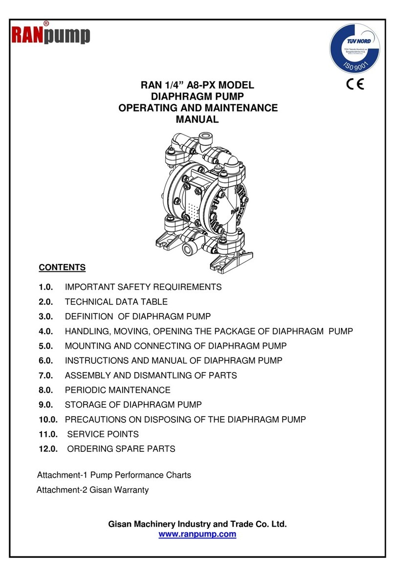
Ranpump F50-AX Operating instructions
Other Ranpump Water Pump manuals
Ranpump
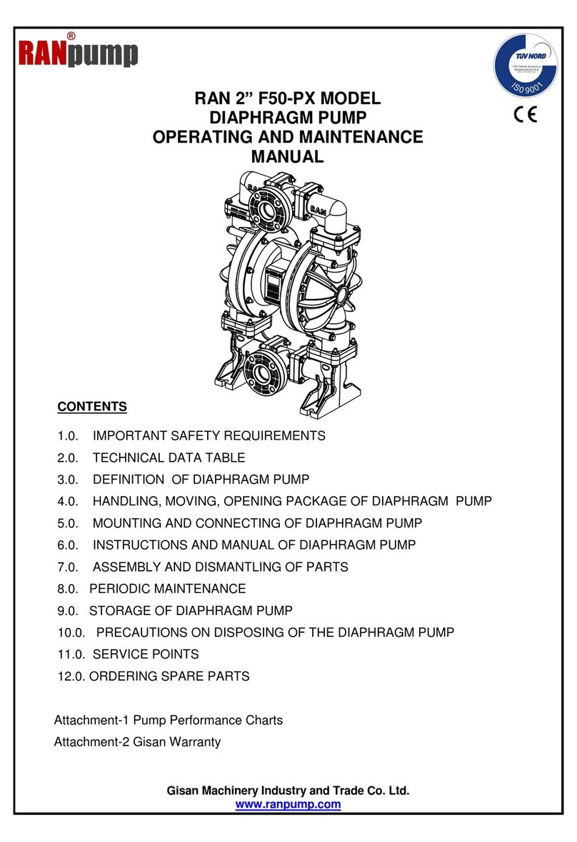
Ranpump F50-PX Operating instructions
Ranpump
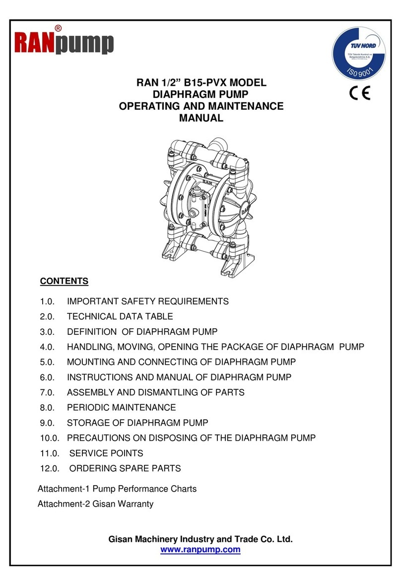
Ranpump B15-PVX Operating instructions

Ranpump
Ranpump TUV NORD G80-SX Operating instructions
Ranpump
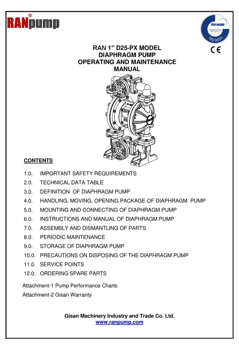
Ranpump D25-PX Operating instructions

Ranpump
Ranpump E40-SX Operating instructions

Ranpump
Ranpump RAN 3" G80-AX Operating instructions

Ranpump
Ranpump B15-PX Operating instructions
Ranpump
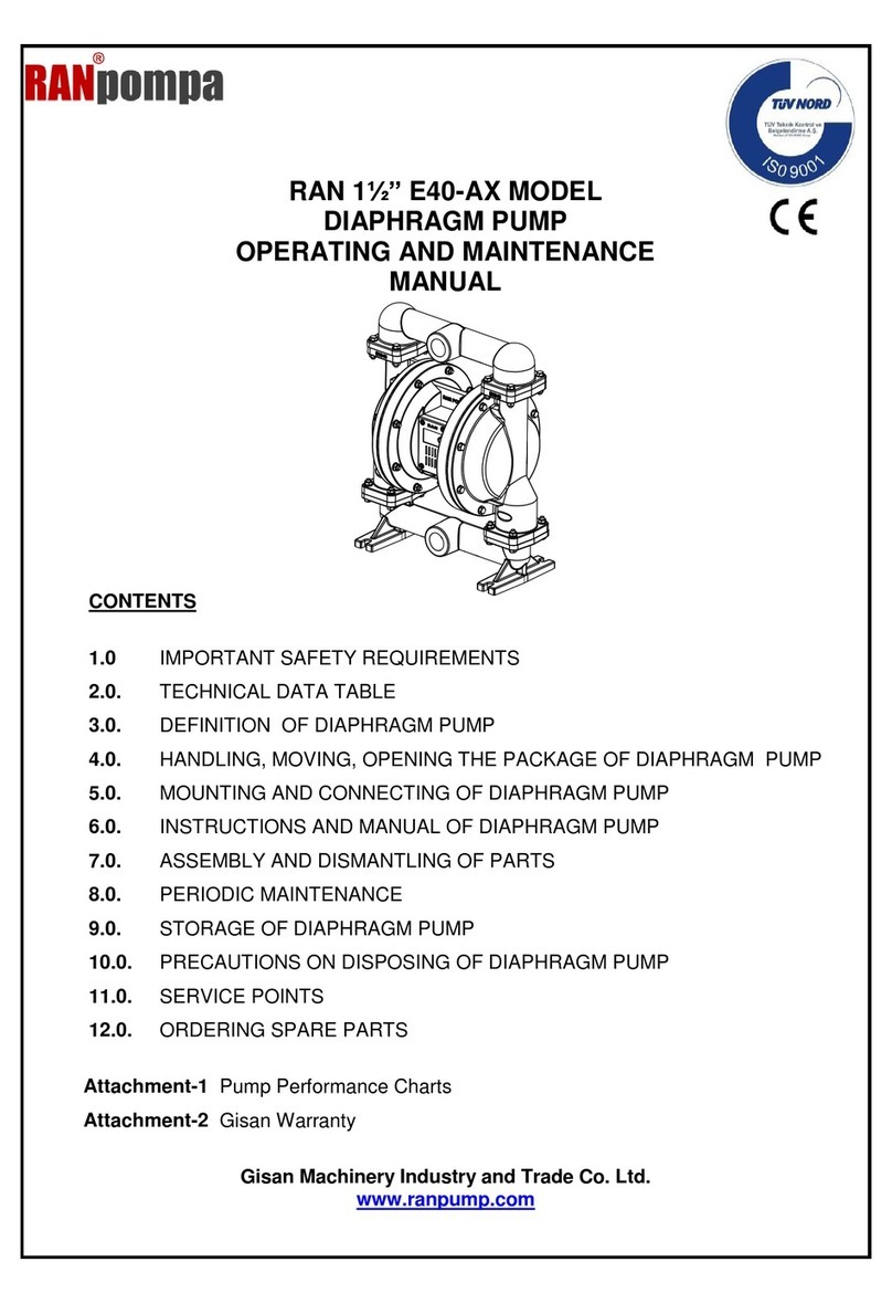
Ranpump E40-AX Operating instructions

Ranpump
Ranpump B15-AX Operating instructions
Ranpump
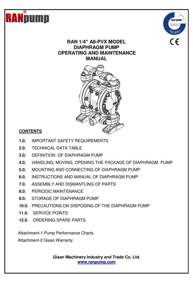
Ranpump A8-PVX Operating instructions
Popular Water Pump manuals by other brands

Watershed Innovations
Watershed Innovations HYDRAPUMP SMART FLEX Instructional manual

Graco
Graco Modu-Flo AL-5M instructions

Messner
Messner MultiSystem MPF 3000 operating instructions

Xylem
Xylem Bell & Gossett WEHT0311M Installation, operation and maintenance instructions

WilTec
WilTec 50739 Operation manual

Franklin Electric
Franklin Electric Little Giant 555702 HRK-360S instruction sheet

Ingersoll-Rand
Ingersoll-Rand PD02P Series Operator's manual

VS
VS ZJ Series Operating instruction

Flotec
Flotec FPZS50RP owner's manual

SKF
SKF Lincoln FlowMaster II User and maintenance instructions

Xylem
Xylem Lowara LSB Series Installation, operation and maintenance instructions

Water
Water Duro Pumps DCJ500 Operating & installation instructions

Action
Action P490 Operating instructions & parts manual

Flo King
Flo King Permacore Reusable Carbon Bag Disassembly. & Cleaning Instructions

ARO
ARO ARO PD15P-X Operator's manual

Pumptec
Pumptec 112V Series Operating instructions and parts manual

Virax
Virax 262070 user manual

Neptun
Neptun NPHW 5500 operating instructions
