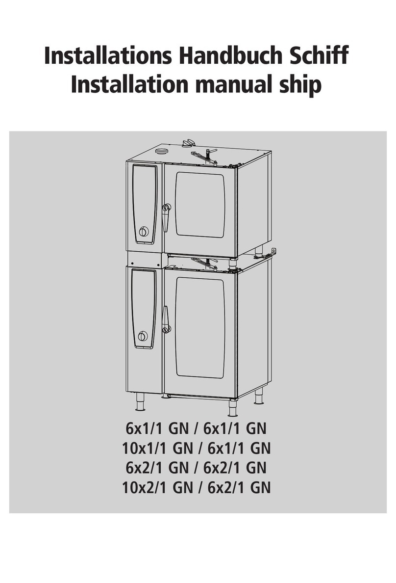
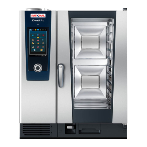
Rational Combi-Duo Gas User manual

EU-west
Combi-Duo Gas
Original-Installationsanleitung
Original Installation Manual

2 / 80 80.51.374_iCombi Pro-iCombi Classic_CD G_IM_V02_Eur-west
de.................................................................................................................................. 3
en.................................................................................................................................. 9
fr ................................................................................................................................... 14
es .................................................................................................................................. 20
it.................................................................................................................................... 26
pt-BR ........................................................................................................................... 32
nl ................................................................................................................................... 38
sv .................................................................................................................................. 44
da.................................................................................................................................. 49
no.................................................................................................................................. 54
fi.................................................................................................................................... 60
el ................................................................................................................................... 65

de
80.51.374_iCombi Pro-iCombi Classic_CD G_IM_V02_Eur-west 3 / 80
Inhaltsverzeichnis
1 Informationen zu dieser Anleitung......................................................................... 4
2 Sicherheit...................................................................................................................... 4
3 Produktbeschreibung................................................................................................ 6
4 Vorbereitungen........................................................................................................... 6
5 Installation.................................................................................................................... 7

1 | Informationen zu dieser Anleitung
de
4 / 80 80.51.374_iCombi Pro-iCombi Classic_CD G_IM_V02_Eur-west
1 Informationen zu dieser
Anleitung
Bei diesem Dokument handelt es sich um
einen vorläufigen Stand der Installations-
anleitung. Bitte beachten Sie den jeweili-
gen Versionsstand und das Datum.
Diese Anleitung beschreibt die Aufstellung
von Combi-Duo für die Geräte:
nLM1: iCombi Pro (iCP) 6-1/1 bis
10-2/1
nLM2: iCombi Classic (iCC) 6-1/1 bis
10-2/1
Diese Anleitung ist eine Ergänzung zur Ge-
räte-Installationsanleitung für iCombi
Pro / iCombi Classic. Lesen Sie die Anlei-
tung vor dem Aufbau durch. Die Installati-
onsanleitung ermöglicht einen sicheren
Umgang mit den Geräten und eine bestim-
mungsgemäße Installation.
Die Abbildungen in dieser Installationsan-
leitung sind beispielhaft und können vom
Gerät abweichen.
Informationen zu Wasseranschluss, Ab-
wasseranschluss, Elektroanschluss und bei
Gasgeräten Gas- und Abgasanschluss fin-
den Sie in der Geräte-Installationsanlei-
tung für iCombi Pro / iCombi Classic.
Alle Informationen aus der Geräte-Installa-
tionsanleitung für iCombi Pro / iCombi
Classic gelten entsprechend.
2 Sicherheit
Die Geräte sind so konstruiert, dass sie bei
vorschriftsgemäßer Installation keine Ge-
fahr darstellen. Die richtige Installation von
Combi-Duo wird in dieser Anleitung be-
schrieben.
Beachten Sie alle Sicherheitshinweise in
der Installationsanleitung zu iCombi Pro /
iCombi Classic.
nBeachten Sie die jeweiligen landesspe-
zifischen und lokalen Vorschriften und
Normen Ihres Landes.
nSchließen Sie das Gerät ausschließlich
entsprechend der Installationsanlei-
tung und den Angaben auf dem Ty-
penschild an.
nSchalten Sie das Gerät aus, wenn Sie es
vom Stromnetz abklemmen oder am
Stromnetz anschließen.
Beachten Sie zusätzlich folgende Gefah-
renhinweise für den Aufbau von Combi-
Duo:
GEFAHR
Gesundheitsschädliche Abgase
Erstickungsgefahr durch unzulässige
Konzentration von
gesundheitsschädlichen Abgasen.
nStellen Sie sicher, dass die
Belüftungsmöglichkeiten im
Aufstellraum ausreichend sind.
nFühren Sie vor der Inbetriebnahme
des Geräts eine Abgasanalyse durch.

2 | Sicherheit de
80.51.374_iCombi Pro-iCombi Classic_CD G_IM_V02_Eur-west 5 / 80
GEFAHR
Austretendes Gas
Explosionsgefahr durch austretendes
Gas.
nSchließen Sie die Gasversorgung.
nBerühren Sie keine elektrischen
Schaltelemente.
nLüften Sie den Raum.
nVermeiden Sie offenes Feuer und
Funken.
nInformieren Sie den zuständigen
Gasversorger oder die zuständige
Feuerwehr mit einem externen
Telefon.
WARNUNG
Quetsch- und Verletzungsgefahr durch
Kippen oder Drehen des Combi-Duo-
Aufbaus
Durch Kippen oder Drehen des Combi-
Duo-Aufbaus kann der Aufbau von der
Aufstellfläche fallen.
nKippen Sie den Aufbau nicht auf der
Aufstellfläche.
nStellen Sie beim Drehen des Aufbaus
sicher, dass das Gewicht der Geräte
gleichmäßig verteilt ist und sich die
Füße oder Lenkrollen des
Untergestells oder der
Nivellierbausatz auf der
Aufstellfläche befinden.
nBefestigen Sie den Aufbau mit vom
Hersteller vorgesehenem Zubehör.
WARNUNG
Verbrennungsgefahr durch heiße
Abluftrohre und Abgasrohre
Die Abluftrohre und Abgasrohre
können während des Betriebs des
Combi-Duo-Aufbaus sehr heiß werden.
nBerühren Sie die Abluftrohre nicht
während des Betriebs.
nBei Gasgeräten: Berühren Sie die
Abgasrohre nicht während des
Betriebs.
VORSICHT
Quetschgefahr durch das Gewicht der
Geräte
Finger, Hände und Füße können unter
den Geräten eingequetscht werden.
nTragen Sie geeignete Schutzkleidung
für Transport und Aufstellung.
nBauen Sie nur ein Gerät nach dem
anderen auf.
nHeben Sie die Geräte nur einzeln auf
die Aufstellfläche.
nBenutzen Sie Tragehilfen, z.B.
Tragegurte des Herstellers.
nBeachten Sie den Massemittelpunkt
der jeweiligen Geräte beim
Anheben.
nTragen Sie die Geräte nur an den
vorgesehenen Hebepunkten.

3 | Produktbeschreibung
de
6 / 80 80.51.374_iCombi Pro-iCombi Classic_CD G_IM_V02_Eur-west
HINWEIS
Beschädigung der Anschlüsse durch
Verschieben
Trennen Sie alle Anschlüsse bevor der
Combi-Duo bewegt wird. Schließen Sie
alle Anschlüsse nach Abschluss der
Arbeiten wieder vorschriftsgemäß an.
Richten Sie das Untergestell oder den
Nivellierbausatz waagerecht aus bevor
Sie den Combi-Duo-Aufbau wieder
aufstellen.
Lenkrollen: Ziehen Sie die
Feststellbremse fest.
3 Produktbeschreibung
Combi-Duo Varianten: Elektrogerät als
unteres Gerät
Folgende Combi-Duo-Varianten sind ver-
fügbar:
Unteres Ge-
rät: Gasgerät
Oberes Gerät Artikelnum-
mer
6-1/1 Gas
Rechtsan-
schlag
6-2/3 oder
6-1/1 Elek-
tro/Gas
60.75.751
6-2/1 Gas
Rechtsan-
schlag
6-2/3 oder
6-1/1 /
6-2/1 Elek-
tro/Gas
60.75.752
6-1/1 Gas
Linksanschlag
6-2/3 oder
6-1/1 Elek-
tro/Gas
60.75.753
6-2/1 Gas
Linksanschlag
6-2/1 Gas
Linksanschlag
60.75.754
Informationen zu weiteren Combi-Duo-
Varianten, wie mit Gasgeräten als unteres
Gerät, finden Sie in den dazugehörigen In-
stallationsanleitungen.
Lieferumfang [ Bild 01]
1 Grundplatte oben 2 Grundplatte un-
ten
3 Füße vorne 4 Füße hinten
5 Abgaskamin 6 Hitzeschutz-Ab-
deckung
7 Schachtabde-
ckung
8 Abgasrohre
9 Ethernet-Kabel
Abmessungen
Beachten Sie, dass sich bei einem Combi-
Duo Aufbau die Anschlusshöhen und die
Einfahrhöhen bei beiden Geräten ändern.
Zeichnungen für den Aufbau und genaue
Abmessungen und Höhe der obersten Ein-
schubschiene für die unterschiedlichen Zu-
sammenstellungen finden Sie in separaten
Maßzeichnungen.
HINWEIS!Wenn die Einschubhöhe über
1600 mm [63 Inch] liegt, bringen Sie den
Sicherheitsaufkleber am Gerät an.
Legende der Maßzeichnungen:
1 Höhe oberster
Einschub
2 Einfahrhöhe obe-
res Gerät
3 Einfahrhöhe un-
teres Gerät
4 Höhe Wasserab-
lauf oberes Gerät
5 Höhe Wasserab-
lauf unteres Ge-
rät
4 Vorbereitungen
Unteres Gerät aufstellen
Um das untere Gerät für den Combi-Duo-
Aufbau aufzustellen, montieren Sie das Ge-
rät auf einem Untergestell mit Füßen, Len-
krollen oder auf einem Nivellierbausatz.
Beachten Sie, dass der Wandabstand des
Combi-Duo-Gerätes mindestens 50mm
[1,97Inch] beträgt.

5 | Installation de
80.51.374_iCombi Pro-iCombi Classic_CD G_IM_V02_Eur-west 7 / 80
Beachten Sie zur Aufstellung des Gerätes
auf dem Untergestell die Beschreibung in
der Installationsanleitung des Gerätes.
Unteres Gerät ausrichten
nUntergestell ausrichten: Stellen Sie das
Gerät auf und prüfen Sie die Ausrich-
tung mit einer Wasserwaage im Gar-
raum. Falls erforderlich, richten Sie die
Lenkrollen oder Füße ebenmäßig aus,
sodass das Gerät sicher steht.
nNivellierbausatz ausrichten: Richten
Sie den Nivellierbausatz aus und prü-
fen Sie die Ausrichtung mit einer Was-
serwaage, bevor Sie das untere Gerät
auf dem Nivellierbausatz positionieren.
5 Installation
Combi-Duo und oberes Gerät aufbauen
HINWEIS
Montage und Befestigung des oberen
Gerätes auf der oberen Grundplatte
Das obere Gerät wird auf der oberen
Grundplatte nur mit drei Schrauben
befestigt. Die vierte Befestigung ist
durch die Abdeckung für Abgasrohre
schwer zugänglich und nicht zwingend
notwendig.
aDas untere Gerät ist auf einem Unter-
gestell mit Füßen oder Lenkrollen oder
einem Nivellierbausatz aufgestellt.
aDie Oberseite des unteren Gerätes ist
sauber und fettfrei.
1. Lösen Sie 3 Schrauben vom Deckel des
unteren Gerätes [ Bild 02].
2. Legen Sie die Combi-Duo Grundplatte
auf das untere Gerät. Richten Sie die
Grundplatte so aus, dass die geschlos-
sene, rechte Seitenblende der Platte
bündig mit der rechten Gerätewand
abschließt.
3. Befestigen Sie die Combi-Duo Grund-
platte mit 3Schrauben [ Bild 03].
4. Montieren Sie die Füße auf der Grund-
platte mit Hutmuttern [ Bild 04].
5. Stellen Sie die Abdeckung für die Ab-
gasrohre auf das untere Gerät
[ Bild 05].
6. Montieren Sie die Halter auf die Unter-
seite der oberen Grundplatte
[ Bild 06].
7. Befestigen Sie die obere Grundplatte
auf den Füßen [ Bild 07].
8. Entfernen Sie den Dichtungsgummi
rund um die Geräteboden-Kante des
oberen Gerätes [ Bild 08].
9. Setzen Sie das obere Gerät mit Hilfe
von Tragegurten auf den Combi-Duo
Zwischenbausatz auf [ Bild 09].
10. Befestigen Sie das obere Gerät mit
mindestens 3 Schrauben auf der obe-
ren Grundplatte des Combi-Duo Zwi-
schenbausatzes [ Bild 10].
11. Montieren Sie den Dichtungsgummi
rund um die Geräteboden-Kante des
oberen Gerätes [ Bild 11].
12. Falls ein Ethernet-Kabel an das obere
Gerät angeschlossen werden soll,
schließen Sie für eine bessere Zugäng-
lichkeit das Kabel an, bevor die Abgas-
und Entlüftungsrohre montiert wer-
den.
13. Befestigen Sie die Abdeckung für die
Abgasrohre mit Hutmuttern und Un-
terlegscheiben.
14. Montieren Sie die Abgas- und Entlüf-
tungsrohre [ Bild 12].
5 | Installation
de
8 / 80 80.51.374_iCombi Pro-iCombi Classic_CD G_IM_V02_Eur-west
15. Montieren Sie den Abgaskamin und
befestigen Sie diesen mit einer Hut-
mutter und Unterlegscheiben
[ Bild 13].
16. Montieren Sie die Schachtabdeckung
auf dem Abgaskamin [ Bild 14].
Türgriff des unteren Gerätes umdrehen
1. Bauen Sie den Türgriff des unteren Ge-
rätes aus: Entfernen Sie die Plastikab-
deckung des Türverschlusses auf der
Türinnenseite, indem Sie die Abde-
ckung zur Türinnenseite schieben und
herausnehmen [ Bild 15].
2. Lösen Sie die Schraube des Türgriffs
mit einem 5mm Innensechskant-
schlüssel [ Bild 16].
3. Ziehen Sie den Türgriff ab, drehen Sie
ihn um 180Grad und bauen Sie den
Türgriff wieder an [ Bild 17].
4. Bringen Sie die Plastikabdeckung wie-
der an [ Bild 18].

en
80.51.374_iCombi Pro-iCombi Classic_CD G_IM_V02_Eur-west 9 / 80
Table of contents
1 Information on this manual ....................................................................................10
2 Safety...........................................................................................................................10
3 Product description .................................................................................................11
4 Preparations ..............................................................................................................12
5 Installation..................................................................................................................12

1 | Information on this manual
en
10 / 80 80.51.374_iCombi Pro-iCombi Classic_CD G_IM_V02_Eur-west
1 Information on this manual
This document is a preliminary version of
the installation manual. Please note the rel-
evant version and date.
This manual describes how to set up
Combi-Duo for the following units:
nLM1: iCombi Pro (iCP) 6-1/1 to
10-2/1
nLM2: iCombi Classic (iCC) 6-1/1 to
10-2/1
This manual is to be used in addition to the
unit installation manual for iCombi Pro /
iCombi Classic. Read the manual before
assembly. The installation manual is there
to ensure that you use the units safely and
install them properly.
The illustrations in this installation manual
are examples only and may differ from the
unit.
You will find information on the water,
waste water, electrical connections, and
for gas units, on the gas and flue connec-
tions in the unit installation manual for
iCombi Pro / iCombi Classic.
All information from the unit installation
manual for iCombi Pro / iCombi Classic
apply accordingly.
2 Safety
This units are designed in such a way that
they present no danger if installed accord-
ing to instructions. This manual describes
how to install the Combi-Duo correctly.
Follow all safety instructions in the install-
ation manual for iCombi Pro / iCombi
Classic.
nAdhere to the relevant local regula-
tions and standards in your country.
nOnly connect the unit in accordance
with the installation manual and the in-
formation on the rating plate.
nSwitch the unit off before disconnect-
ing the mains power or connecting to
the mains.
Also note the following hazard warnings
when setting up the Combi-Duo:
DANGER
Toxic exhaust fumes
Risk of asphyxiation from unauthorised
concentration of harmful exhaust gases.
nEnsure that the ventilation options in
the installation area are adequate.
nPerform a flue gas analysis prior to
commissioning the unit.
DANGER
Leaking gas
Risk of explosion from leaking gas.
nClose the main gas supply.
nDo not touch any electrical controls.
nVentilate the room.
nAvoid naked flames or sparking.
nInform the responsible gas supplier
or the responsible fire service with
an external telephone.

3 | Product description en
80.51.374_iCombi Pro-iCombi Classic_CD G_IM_V02_Eur-west 11 / 80
WARNING
Risk of crushing and injury from
tipping or turning of the Combi-Duo
system.
Tipping or turning the Combi-Duo
system may make it fall off the
installation surface.
nDo not tip the system onto the
installation surface.
nWhen turning the body, make sure
that the weight of the equipment is
evenly distributed and that the feet
or castors of the base frame or the
levelling kit are on the installation
surface.
nSecure the system using the
appropriate accessories from the
manufacturer.
WARNING
Risk of burns from hot exhaust pipes
and flue pipes
The exhaust and flue pipes can become
very hot when operating the Combi-
Duo system.
nDo not touch the exhaust pipes
during operation.
nFor gas units: Do not touch the flue
pipes during operation.
CAUTION
Risk of crushing due to the weight of
the units
Fingers, hands and feet could be
crushed beneath the units.
nWear appropriate protective
clothing for transport and
installation.
nOnly install one unit at a time.
nOnly lift one unit at a time onto the
installation surface.
nUse carrying aids such as carrying
straps supplied by the manufacturer.
nNote the centre of mass when lifting
up each unit.
nOnly lift the units at the intended
lifting points.
NOTICE
Damage to the connections due to
moving
Unplug all connections before moving
the Combi-Duo. After the work has
been carried out, reconnect them all in
accordance with the instructions.
Level the stand or levelling kit before
setting up the Combi-Duo again.
Swivel castors: Apply the parking
brakes.
3 Product description
Combi-Duo variants: Electric unit as the
bottom unit
The following Combi-Duo variants are
available:

4 | Preparations
en
12 / 80 80.51.374_iCombi Pro-iCombi Classic_CD G_IM_V02_Eur-west
Bottom unit:
Gas unit
Top unit Article num-
ber
6-1/1 Gas
right-sided
hinge
6-2/3 or
6-1/1 Elec-
tric/Gas
60.75.751
6-2/1 Gas
right-sided
hinge
6-2/3 or
6-1/1 /
6-2/1 Elec-
tric/Gas
60.75.752
6-1/1 Gas
left-sided
hinge
6-2/3 or
6-1/1 Elec-
tric/Gas
60.75.753
6-2/1 Gas
left-sided
hinge
6-2/1 Gas
left-sided
hinge
60.75.754
You can find further information on other
Combi-Duo variants, such as with gas
units as the bottom unit, in the associated
installation manuals.
Scope of delivery [ Photo 01]
1 Base plate top 2 Base plate below
3 Feet at front 4 Feet at the rear
5 Exhaust gas stack 6 Heat protection
cover
7 Shaft cover 8 Exhaust pipe
9 Ethernet cable
Dimensions
Note that with a Combi-Duo system, the
connection heights and access heights
change for both units. You can find draw-
ings of the setup and precise dimensions
and height of the top rack rail for the dif-
ferent configurations in separate dimen-
sion drawings.
NOTICE!If the rack height is over 1600
mm [63 inches], affix the safety label to
the unit.
Key for dimension drawings:
1 Height of top
rack
2 Top unit access
height
3 Bottom unit ac-
cess height
4 Height of top
unit water drain
5 Height of bottom
unit water drain
4 Preparations
Position the bottom unit
In order to position the bottom unit for the
Combi-Duo setup, mount the unit onto a
stand with feet, castors or a levelling kit.
Note that the wall clearance of the Combi-
Duo unit is at least 50 mm [1.97 inches].
Note the description in the unit's installa-
tion manual for positioning the unit on the
stand.
Align the bottom unit
nAlign the stand: Position the unit and
check the alignment with a spirit level
in the cooking cabinet. If necessary,
align the castors or feet evenly so that
the unit is standing securely.
nAlign the levelling kit: Align the level-
ling kit and check the alignment with a
spirit level before positioning the
lower unit on the levelling kit.
5 Installation
Setting up the Combi-Duo and the top
unit
NOTICE
Mounting and attachment of the top
unit on the top base plate
The top unit is attached to the top base
plate with only three screws. The fourth
attachment is difficult to access through
the cover for flue pipes and is not
absolutely necessary.

5 | Installation en
80.51.374_iCombi Pro-iCombi Classic_CD G_IM_V02_Eur-west 13 / 80
aThe bottom unit is placed on a stand
with feet or castors or an auto levelling
kit.
aThe top side of the bottom unit is
clean and free of grease.
1. Loosen 3 screws from the lid of the
bottom unit [ Photo 02].
2. Place the Combi-Duo base plate on
the lower unit. Align the base plate so
that the closed, right side panel is flush
with the right unit wall.
3. Secure the Combi-Duo base plate with
3 screws [ Photo 03].
4. Install the feet on the base plate with
cap nuts [ Photo 04].
5. Place the cover for the flue pipes on
the bottom unit [ Photo 05].
6. Install the bracket on the bottom side
of the top base plate [ Photo 06].
7. Attach the top base plate to the feet
[ Photo 07].
8. Remove the rubber seal around the
unit feet edges of the top unit
[ Photo 08].
9. Place the top unit on the Combi-Duo
Intermediate Assembly Kit with the
help of carrying straps [ Photo 09].
10. Secure the top unit base plate of the
Combi-Duo Intermediate Assembly
Kit with at least 3 screws
[ Photo 10].
11. Install the rubber seal around the bot-
tom edge of the top unit
[ Photo 11].
12. If an Ethernet cable is to be connected
to the top unit, connect the cable be-
fore assembling the exhaust and vent-
ilation pipes for better accessibility.
13. Attach the cover for the flue pipes with
cap nuts and washers.
14. Mount the exhaust and ventilation
pipes [ Photo 12].
15. Mount the exhaust gas stack and at-
tach this with a cap nut and washer
[ Photo 13].
16. Mount the shaft cover on the exhaust
gas stack [ Photo 14].
Turn the door handle of the bottom unit
1. Disassemble the door handle of the
bottom unit: Remove the plastic cover
of the door lock on the inner side of
the door, by sliding the cover towards
the inner side of the door and taking it
out [ Photo 15].
2. Loosen the screws of the door handle
with a 5 mm Allen key [ Photo 16].
3. Pull the door handle off, turn it 180
degrees and reattach the door handle
[ Photo 17].
4. Apply the plastic cover [ Photo 18].

fr
14 / 80 80.51.374_iCombi Pro-iCombi Classic_CD G_IM_V02_Eur-west
Table des matières
1 À propos de ce guide ...............................................................................................15
2 Sécurité .......................................................................................................................15
3 Description du produit............................................................................................17
4 Préparatifs..................................................................................................................18
5 Installation..................................................................................................................18

1 | À propos de ce guide fr
80.51.374_iCombi Pro-iCombi Classic_CD G_IM_V02_Eur-west 15 / 80
1 À propos de ce guide
Le présent document constitue une ver-
sion provisoire du guide d'installation.
Veuillez vérifier le numéro et la date de la
version.
Ce guide décrit l’installation du kit Combi-
Duo pour les appareils suivants:
nLM1: iCombi Pro (iCP) 6-1/1 à
10-2/1
nLM2: iCombi Classic (iCC) 6-1/1 à
10-2/1
Ce guide constitue un complément au
guide d’installation des appareils iCombi
Pro / iCombi Classic. Veuillez lire le guide
en entier avant le montage. Ce guide d'ins-
tallation garantit une utilisation sécurisée
de l'appareil et une installation conforme.
Les illustrations dans ce guide d'installation
sont données à titre d'exemples et peuvent
être différentes de celle de l'appareil.
Pour obtenir les informations relatives aux
raccordements aux circuits d'alimentation
en eau, d'évacuation des eaux usées, d'ali-
mentation électrique et, dans le cas des
appareils fonctionnant au gaz, aux raccor-
dements d'alimentation en gaz et d'éva-
cuation des gaz de combustion, consultez
le guide d'installation des appareils iCombi
Pro / iCombi Classic.
Toutes les informations contenues dans le
guide d’installation des appareils iCombi
Pro / iCombi Classic s’appliquent en
conséquence.
2 Sécurité
Les appareils sont conçus de manière à
n'engendrer aucun danger en cas d'installa-
tion conforme aux instructions. L'installa-
tion correcte de Combi-Duo est décrite
dans ce guide.
Veuillez respecter toutes les consignes de
sécurité énoncées dans le guide d'installa-
tion des appareils iCombi Pro / iCombi
Classic.
nVeuillez respecter les réglementations
et normes locales et nationales de
votre pays.
nEffectuez le raccordement de l'appareil
en respectant strictement les
consignes du guide d'installation et les
indications figurant sur la plaque si-
gnalétique.
nÉteignez l'appareil avant de le débran-
cher de l'alimentation secteur ou de le
rebrancher.
Veuillez tenir compte également des men-
tions de danger suivantes concernant le
montage du kit Combi-Duo :
DANGER
Gaz de combustion nocifs pour la santé
Risque d’asphyxie due à une
concentration trop élevée de gaz de
combustion nocifs pour la santé.
nVeillez à ce que le système d'aération
dans le local d'installation soit
suffisant.
nAvant la mise en service, procédez à
une analyse des gaz de combustion.

2 | Sécurité
fr
16 / 80 80.51.374_iCombi Pro-iCombi Classic_CD G_IM_V02_Eur-west
DANGER
Échappement de gaz
Risque d’explosion dû à une fuite de
gaz.
nCoupez l'alimentation en gaz.
nNe touchez à aucun élément de
circuit électrique.
nAérez la pièce.
nÉvitez les flammes nues et les
étincelles.
nInformez-en le fournisseur de gaz
concerné ou l’unité de sapeurs-
pompiers locale en les appelant avec
un téléphone à l’extérieur des locaux.
AVERTISSEMENT
Risque de pincements ou de blessures
dus à un mouvement de basculement
ou de rotation de l’ensemble du kit
Combi-Duo
Un mouvement de basculement ou de
rotation de l’assemblage du kit Combi-
Duo peut entraîner sa chute depuis sa
surface d’installation.
nNe basculez pas l'assemblage sur la
surface d'installation.
nEn cas de rotation de l’assemblage,
assurez-vous que le poids des
appareils est réparti uniformément
et que les pieds ou les roulettes
pivotantes de la table de
soubassement ou que le kit de mise
à niveau soient bien placés sur la
surface d'installation.
nFixez l'appareil à l'aide de l'accessoire
prévu par le fabricant.
AVERTISSEMENT
Risque de brûlures dues aux tuyaux
très chauds d'évacuation de l’air et des
gaz de combustion
Les tuyaux d'évacuation de l’air et des
gaz de combustion peuvent devenir
brûlants pendant le fonctionnement des
appareils constituant le Combi-Duo.
nNe touchez pas les tuyaux
d’évacuation de l’air pendant le
fonctionnement de l’appareil.
nPour les appareils à gaz: Ne touchez
pas les tuyaux d’évacuation des gaz
de combustion pendant le
fonctionnement de l’appareil.
ATTENTION
Risque de pincements en raison du
poids de l'appareil
Les doigts, les mains et les pieds
peuvent être écrasés sous l'appareil.
nPortez un équipement de protection
approprié pour le transport et
l'installation.
nMontez un appareil à la fois.
nLevez les appareils sur la surface
d'installation, un à la fois.
nUtilisez les accessoires de portage,
par exemple les sangles du fabricant.
nTenez compte du centre de gravité
de chaque appareil au moment du
levage.
nPortez les appareils uniquement par
les points de levage prévus à cet
effet.

3 | Description du produit fr
80.51.374_iCombi Pro-iCombi Classic_CD G_IM_V02_Eur-west 17 / 80
INFORMATION
Détérioration des branchements liée
au déplacement de l'appareil
Retirez tous les branchements avant de
déplacer le Combi-Duo. Rebranchez-les
tous selon les consignes à la fin des
opérations.
Réglez la table de soubassement ou le
kit de mise à niveau pour qu’ils soient
bien de niveau avant de reposer
l’assemblage Combi-Duo.
Roues pivotantes : Serrez le frein
d'arrêt.
3 Description du produit
Variantes Combi-Duo : Appareil
électrique comme appareil du bas
Les variantes Combi-Duo suivantes sont
disponibles :
Appareil du
bas : Appareil
à gaz
Appareil du
haut
Numéro d’ar-
ticle
6-1/1 Gaz
Charnière à
droite
6-2/3 ou
6-1/1 Élec-
trique/Gaz
60.75.751
6-2/1 Gaz
Charnière à
droite
6-2/3 ou
6-1/1 /
6-2/1 Élec-
trique/Gaz
60.75.752
6-1/1 Gaz
Charnière à
gauche
6-2/3 ou
6-1/1 Élec-
trique/Gaz
60.75.753
6-2/1 Gaz
Charnière à
gauche
6-2/1 Gaz
Charnière à
gauche
60.75.754
Veuillez vous reporter aux guides d'instal-
lation correspondants pour obtenir des in-
formations d’autres variantes Combi-Duo,
par exemple la combinaison avec un appa-
reil à gaz placé en bas.
Contenu du kit Combi-Duo [ Image 01]
1 Plaque de base
en haut
2 Plaque de base
en bas
3 Pieds avant 4 Pieds arrière
5 Cheminée gaz de
combustion
6 Bouclier ther-
mique
7 Cache de conduit 8 Tuyaux évacua-
tion gaz de com-
bustion
9 Câble Ethernet
Dimensions
Veuillez tenir compte qu’avec un assem-
blage Combi-Duo, les hauteurs de raccor-
dement et d'insertion changent pour les
deux appareils. Les schémas d’assemblage,
les dimensions exactes et la hauteur du rail
du niveau supérieur pour les différentes
combinaisons sont disponibles dans des
schémas cotés séparés.
INFORMATION !Lorsque la hauteur des
niveaux est supérieure à 1600 mm [63
pouces], apposez l’autocollant de sécurité
sur l’appareil.
Légendes des schémas cotés :
1 Hauteur niveau
supérieur
2 Hauteur d'inser-
tion appareil du
haut
3 Hauteur d'inser-
tion appareil du
bas
4 Hauteur évacua-
tion d’eau appa-
reil du haut
5 Hauteur évacua-
tion d’eau appa-
reil du bas

4 | Préparatifs
fr
18 / 80 80.51.374_iCombi Pro-iCombi Classic_CD G_IM_V02_Eur-west
4 Préparatifs
Installation de l’appareil du bas
Pour installer l’appareil du bas dans l'as-
semblage Combi-Duo, montez l’appareil
sur une table de soubassement dotée de
pieds, de roulettes pivotantes ou d’un kit
de mise à niveau.
Respectez un écartement minimal de 50
mm [1,97pouce] par rapport à la paroi de
l’appareil Combi-Duo.
Pour la pose de l’appareil sur la table de
soubassement, reportez-vous à la descrip-
tion donnée dans le guide d’installation de
l'appareil.
Ajuster la mise à niveau de l’appareil du
bas
nAjuster la mise à niveau de la table de
soubassement : Posez l’appareil et vé-
rifiez sa planéité avec un niveau à bulle
dans l’enceinte de cuisson. Si néces-
saire, réglez la hauteur des roues pivo-
tantes ou des pieds comme il convient
afin que l'appareil soit stable.
nAjuster le kit de mise à niveau Ajustez
le kit de mise à niveau et vérifiez sa
planéité avec un niveau à bulle avant
de positionner l'appareil du bas sur le
kit de mise à niveau.
5 Installation
Monter le kit Combi-Duo et l’appareil du
haut
INFORMATION
Montage et fixation de l’appareil du
haut sur la plaque de base supérieure.
L’appareil du haut est fixé sur la plaque
de base supérieure uniquement par
trois vis La quatrième fixation est
difficilement accessible car il faut passer
par l’habillage des tuyaux d'évacuation
des gaz de combustion et elle n’est pas
indispensable.
aL'appareil du bas est posé sur une table
de soubassement dotée de pieds, de
roulettes pivotantes ou d’un kit de
mise à niveau.
aLa partie supérieure de l’appareil du
bas est propre et non grasse.
1. Desserrez les 3 vis du couvercle de
l’appareil du bas [ Image 02].
2. Posez la plaque de base Combi-Duo
sur l’appareil en bas. Ajustez la position
de la plaque de sorte que le panneau
latéral fermé de droite de la plaque soit
aligné sur la paroi de droite de l’appa-
reil.
3. Fixez la plaque de base Combi-Duo à
l'aide de 3 vis [ Image 03].
4. Montez les pieds sur la plaque de base
à l'aide de boulons à tête ronde
[ Image 04].
5. Placez l’habillage des tuyaux d’évacua-
tion des gaz de combustion sur l’appa-
reil du bas [ Image 05].
6. Montez les supports sur la face infé-
rieure de la plaque du haut
[ Image 06].

5 | Installation fr
80.51.374_iCombi Pro-iCombi Classic_CD G_IM_V02_Eur-west 19 / 80
7. Fixez la plaque de base supérieure sur
les pieds [ Image 07].
8. Retirez le caoutchouc d'étanchéité en-
tourant la bordure inférieure de l’appa-
reil du haut [ Image 08].
9. Utilisez les sangles pour poser l’appa-
reil du haut sur le kit intermédiaire
Combi-Duo [ Image 09].
10. Utilisez au moins 3 vis pour fixer l'ap-
pareil du haut sur la plaque supérieure
du kit intermédiaire du Combi-Duo
[ Image 10].
11. Montez le caoutchouc d'étanchéité en-
tourant la bordure inférieure de l’appa-
reil du haut [ Image 11].
12. Si un câble Ethernet est branché sur
l’appareil du haut, branchez le câble
avant de monter les tuyaux d'extrac-
tion d'air et d'évacuation des gaz de
combustion car il sera ainsi plus facile-
ment accessible.
13. Fixez l’habillage des tuyaux d’évacua-
tion des gaz de combustion à l’aide de
boulons à tête ronde et de rondelles.
14. Montez les tuyaux d'évacuation des
gaz de combustion et d’extraction d'air
[ Image 12].
15. Montez la cheminée d’évacuation des
gaz de combustion et fixez-la avec un
boulon à tête ronde et des rondelles
[ Image 13].
16. Montez le cache de conduit sur la che-
minée des gaz de combustion
[ Image 14].
Retourner la poignée de porte de
l'appareil du bas
1. Démontez la poignée de porte de l’ap-
pareil du bas : Retirez le cache plas-
tique du verrouillage de porte sur la
face intérieure de la porte en faisant
glisser le cache pour le dégager
[ Image 15].
2. Desserrez la vis de la poignée de porte
avec une clé Allen de 5 mm
[ Image 16].
3. Retirez la poignée de porte, tournez-la
à 180et remontez la poignée ainsi in-
versée [ Image 17].
4. Remettez en place le cache en plas-
tique [ Image 18].

es
20 / 80 80.51.374_iCombi Pro-iCombi Classic_CD G_IM_V02_Eur-west
Índice
1 Información acerca de este manual ......................................................................21
2 Seguridad ...................................................................................................................21
3 Descripción del producto........................................................................................23
4 Preparativos...............................................................................................................24
5 Instalación ..................................................................................................................24
Other manuals for Combi-Duo Gas
1
Table of contents
Languages:
Other Rational Oven manuals

Rational
Rational SelfCooking Center User manual

Rational
Rational Combi-Duo Gas User manual

Rational
Rational SCC WE 61G User manual

Rational
Rational LM1 Series User manual

Rational
Rational SelfCooking Center User manual

Rational
Rational SelfCookingCenter whitefficiency Installation guide

Rational
Rational iCombi Pro XS 6-2/3 User manual

Rational
Rational iVario Pro L User manual

Rational
Rational Combi Duo 6x1/1 GN / 6x1/1 GN User manual

Rational
Rational iVario 2-XS User manual