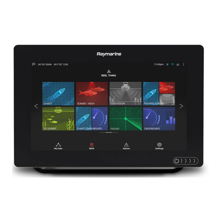
Raymarine Raydata User manual

RAYDATAInstallationandOperationHandbook
RayData
InstallationandOperationHandbook
IMPORTANT NOTICE
This device is only an aid to navigation. Its accuracy can be
affected by many factors, including equipment failure or defects,
environmental conditions and improper handling or use.
It is the user’s responsibility to exercise common prudence and
navigational judgement, and this device should not be relied upon
as a substitute for such prudence and judgement.

RAYDATA
In
s
t
a
ll
a
ti
on
a
n
d
O
p
eratio
n
H
a
n
dbook
RAYMARINE products are supported by a network of Authorized
Service Representatives. For information on Raymarine products and
services, contact either of the following:
UNITED STATES Raymarine Incorporated
22 Cotton Road
Unit H
Nashua
New Hampshire 03063-4219
Telephone: +1 603 881 5200
Fax: +1 603 864 4756
Raymarine Limited
Anchorage Park
Portsmouth
Hampshire PO3 5TD
England
Telephone: +44 (0) 2392 693611
Fax: +44 (0) 2392 694624
EUROPE
Copyright © Raymarine 2001
To the best of our knowledge, the technical and graphical information
contained in this handbook was correct when it went to press. However,
the Raymarine policy of continuous improvement and updating may
change product specifications without prior notice. Therefore,
unavoidable differences may occur, between the product and the
handbook, from time to time, for which liability cannot be accepted by
Raymarine.
SeaTalk and RayData are trademarks of Raymarine.

61

Preface i
Preface
Congratulations on the purchase of your RayData™ multi-function
instrument from Raymarine.
This handbook contains very important information on the installation
and operation of your new equipment. In order to get the best results in
operationandperformance,please read thishandbookthoroughly.
HowthisHandbookis Organised
Thishandbookisdivided into thefollowingchapters:
Chapter 1: Introduces the RayData, its features and its use, either
stand-alone or as part of a larger system.
Chapter 2: ProvidesinstructionsforinstallingtheRayData.
Chapter 3: Explainshowto start using theRayData,including
instructionsforturningiton,interpreting and changing thedatadisplays,
changingthelighting,andsending/receivingamanoverboardwarning.
Chapter 4: Providesinstructionsforsettingupthe RayData defaults,
suchasthenumericalunitsused, to suit yourprefences.Italsoexplains
how to calibrate your speed transducer to obtain an accurate speed
display.
Chapter 5: Explainshowtosetupalarmthresholdvalues,andhow to
dealwithalarmconditions.
Chapter 6: Providesdetailed reference information oneachofthe
displaypages,includingdepth,temperature,speed,logandnavigation
displays.
Chapter 7: Providesinformationtohelpyouto resolve any problems
youmayencounterwhenusingyour RayData.
Appendix A: ProvidesdetailsofthefunctionsofalltheRayDatakey
presses.
Appendix B: Liststhedatasources that maybeusedbythe RayData,
and their priorities.
Appendix C: Liststhesystemspecifications.
A glossary, index and the warranty registration card are included at the
end of the handbook, and a mounting template is attached just inside
the rear cover.

ii RAYDATAInstallationandOperationHandbook
Recommended Use
WhenyoufirstreceiveyourRayData, you should readChapters1and2,
andinstalltheequipment.Thenread Chapter 3, andfamiliariseyourself
with the basic operation of the RayData. You may wish to refer to the
RayData Quick Reference Card and to Chapter 6 for more details about
some displays.
Whenyouarehappyusingthe RayData, read Chapters4and5,decide
howyouwishtosetupyourdefaultsand alarms, and follow the
instructionsinthosechaptersto make yourchanges.Chapter4also
explainshowtocalibratethespeedsothatyou obtain an accurate
readingforyourvessel.
If you experience any difficulties with your RayData, refer to Chapter 7.
Conventions
Throughoutthishandbook,thekeysareshowninbold capitals: for
example, SPEED.
Terms in bold type are included in the glossary.
Warranty
To verify your RayData ownership, please take a few minutes to fill out
the warranty registration card found at the end of this handbook. It is
very important that you complete the owner information and return the
card to the factory in order to receive full warranty benefits.

Contents iii
Contents
Chapter 1: Introduction ......................................................1
1.1 Overview........................................................................... 1
1.2 Standard Displays and Facilities ......................................... 2
Data Displayed.................................................................. 2
Facilities............................................................................ 2
1.3 Additional Displays and Facilities ........................................ 2
Data Displayed.................................................................. 3
Facilities............................................................................ 3
Data Sent.......................................................................... 4
Chapter 2: Installation ........................................................5
2.1 Introduction ....................................................................... 5
2.2 EMC Installation and Service Guidelines............................. 6
IMPORTANT NOTE .......................................................... 6
Installation......................................................................... 6
Check Before Going to Sea................................................ 7
Servicing and Safety.......................................................... 7
2.3 Packing List....................................................................... 7
2.4 Installing the Depth and Speed Transducers ....................... 8
Transducer Type ............................................................... 8
Installing the Speed Transducer (Through Hull)................... 9
Siting of Depth Transducer (Standard Through Hull).......... 10
2.5 Transducer Cabling ......................................................... 10
2.6 Mounting the RayData ..................................................... 11
Panel Mounting ............................................................... 11
Trunnion Mounting .......................................................... 12
2.7 RayData Connections...................................................... 13
Stand-Alone System........................................................ 13
Larger System................................................................. 14

iv RAYDATAInstallationandOperationHandbook
Chapter 3: Getting Started ...............................................17
3.1 Introduction ..................................................................... 17
3.2 Using the Keys ................................................................ 18
3.3 Turning the RayData On and Off ...................................... 18
3.4 The Display ..................................................................... 19
Data Value ...................................................................... 19
Text Description .............................................................. 19
Trend Arrow .................................................................... 20
Additional Information ...................................................... 20
3.5 Changing the Information Displayed ................................. 20
3.6 Changing the Lighting...................................................... 22
3.7 Using the Locked Heading Facility .................................... 23
3.8 Man Overboard (MOB) .................................................... 24
Sending an MOB Warning ............................................... 24
Cancelling an MOB Warning ............................................ 25
3.9 Key Functions ................................................................. 25
Chapter 4: Setup and Calibration ....................................27
4.1 Introduction ..................................................................... 27
4.2 Using the Setup Pages .................................................... 28
4.3 Setup Options ................................................................. 28
Depth Offset.................................................................... 30
Sounder Control .............................................................. 31
Response Level .............................................................. 31
Mode .............................................................................. 31
4.4 Speed Calibration ............................................................ 31
Automatic Calibration....................................................... 32
Manual Calibration........................................................... 33

Contents v
Chapter 5: Alarms .............................................................35
5.1 Introduction ..................................................................... 35
5.2 Setting Alarms ................................................................. 36
Turning Alarms On and Off............................................... 37
Adjusting the Shallow Alarm Limit ..................................... 37
Adjusting the Deep Alarm Limit......................................... 39
Adjusting the Anchor and Temperature Alarm Limits ......... 40
5.3 Handling Alarms .............................................................. 41
Alarm Notification ............................................................ 41
Dealing with an Alarm ...................................................... 42
Chapter 6: The Display Pages .........................................43
6.1 Introduction ..................................................................... 43
6.2 The Depth Chapter .......................................................... 44
Main Depth ..................................................................... 44
Minimum Depth .......................................................... 46
Shallow Alarm............................................................. 46
Deep Alarm ................................................................ 47
Anchor Alarm.............................................................. 47
Sea Temperature ............................................................ 48
Temperature Alarm..................................................... 48
3-Line Page (Speed, Depth and Temperature).................. 49
6.3 The Speed Chapter ......................................................... 50
Speed Through Water ..................................................... 50
Maximum Speed ........................................................ 51
Average Speed .......................................................... 52
Speed Over Ground (SOG) ......................................... 52
Log/Trip .......................................................................... 53
3-Line Page .................................................................... 53
6.4 The Nav Chapter ............................................................. 54

vi RAYDATAInstallationandOperationHandbook
Position........................................................................... 55
Time & Date................................................................ 55
Waypoint/Bearing/Distance ............................................. 56
BRG/DTW/COG/SOG ................................................ 56
TTG/ETA/VMG........................................................... 57
Heading .......................................................................... 58
Boat Heading and Rudder Angle ................................. 58
Locked Heading .............................................................. 59
Locking and Unlocking the Heading ............................. 59
Changing the Locked Heading .................................... 60
Locked Heading Over-ride .......................................... 60
Chapter 7: Problem Solving.............................................61
7.1 Introduction ..................................................................... 61
7.2 Fault Finding ................................................................... 62
7.3 Absent Data .................................................................... 62
7.4 Self Test Mode ................................................................ 63
7.5 Factory Reset.................................................................. 63
7.6 Maintenance ................................................................... 64
7.7 Servicing ......................................................................... 64
Appendix A: Key Functions .............................................67
Appendix B: Data Sources...............................................69
B.1 Possible Configurations................................................... 70
B.2 SeaTalk and NMEA Data Display..................................... 71
Appendix C: Specification ...............................................73
Glossary .............................................................................75
G.1 Terms ............................................................................ 75
G.2 Abbreviations ................................................................. 75
Index ...................................................................................77

Chapter1:Introduction 1
Chapter1:Introduction
1.1 Overview
TheRayDataisa multi-function digitaldisplay,providingacleardisplay
ofimportantnavigationalinformationeither above orbelowdeck.
The RayData can be used in two ways:
• As a stand-alone unit, with depth and speed sensors, to display
depth, speed, temperature and log information.
• As part of a larger system, sharing data with other instruments
connected via a SeaTalk®interface, and/or receiving NMEA 0183
datafromother equipment.Sucha systemmayinclude morethan
oneRayData.
Mostofthestandarddatavaluescanbedisplayedinasingle-line
readout, with easy to read 1” (25mm) high digital characters. In addition,
a three-line display showing depth, speed and temperature can be
selected. Other displays show two to four items of related data on the
screen at one time.
OperationoftheRayDatarevolves around a“ChapterandPages”
concept.Therearefour chapters, eachwithmultiplepages and sub-
pagescontainingrelatedinformation.The chapters areDepth,Speed,
Nav and Setup; each of the first three of these is accessed using its own
dedicatedkey.Screenpromptsguide you throughthevariouspages,
makingtheRayDataan easy instrumenttouse.
Manydefaultsfor the datadisplayscan be setasrequired, so that,for
example,informationis presented inthepreferred units.
The RayData keys are always lit, taking the guesswork out of night-time
use.Thedisplaycan be backlitinlowlightconditions,andthelighting
intensity and the contrast can be adjusted.
The unit is lightweight and waterproof.

2 RAYDATAInstallationandOperationHandbook
1.2 Standard Displays and Facilities
When used as a stand-alone unit, with its direct-connection depth and
speed and temperature transducers, the RayData provides a range of
usefuldataandfacilities.
Data Displayed
TheRayDatastand-alonesystemcandisplaythefollowingitemsof
data:
•Depth,providingaclearindicationofthewaterdepthandhow it is
changing,fordetectionofshallowsandseafloortopography
•Minimum depth encountered,allowingyoutocheck the clearance
achievedonyourroute
•Speed throughthewater,givingyourcurrent speed together witha
graphicalindicationofwhetheryourspeedis increasing or decreasing
•Maximum speed achieved, for comparativepurposes
•Average speed,fortrip timing andcomparativepurposes
•Log and trip counters,to indicate distance travelledonthecurrent
tripandthetotal travelled todate
•Sea surface temperature, allowing you to detect suitable fishing
sites and determine whether the water is comfortable for swimming
Thespeed,depthandtemperaturecanallbedisplayed at once in a
three-linedisplaypage,allowingyouto monitor their statusataglance.
Facilities
The minimum depth, maximum speed, average speed and trip counter
can all be reset independently when required.
Alarm limits can be set for various depth and temperature functions,
and alarm conditions are reported on the screen together with an
audible alarm.
1.3AdditionalDisplaysandFacilities
BecausetheRayDatais compatible withtheRaymarine SeaTalk
standard, and with the NMEA 0183 standard, it can be installed as part
ofalargersystem and displaydatasentby other instruments,suchasa
navigation instrument or autopilot. A general diagram of such a system
is shown on the following page.

Chapter1:Introduction 3
D3032-1
2
2
2
Data Displayed
The RayData can display the following additional items of data, if the
appropriate information is available over a SeaTalk or NMEA interface:
• Heading
• Lockedheading
• Position, as Lat/Long or TD
• Speedover ground (SOG)
• Course over ground (COG)
• Waypoint number
• Bearing to waypoint (BTW) and distance to waypoint (DTW)
• Time and date
• Cross track error (XTE) distance
• Time to go (TTG), estimated time of arrival (ETA) and velocity made
good(VMG)to the nextwaypoint
• Boatheadingandrudderangle
Facilities
If the primary position data is lost, the RayData performs dead
reckoning calculations from the speed and heading data (if available),
and provides a DR position.
Whenheadinginformationisavailable,theheadingcanbelockedwitha
simple keypress. The Locked Heading display then shows the locked
heading (Course to Steer) and the actual heading, plus a graphic off-
course indication.

4 RAYDATAInstallationandOperationHandbook
The RayData will display a subset of the SeaTalk alarms sent by other
instruments on the system, including Watch alarms. It can also send,
display and cancel a Man Overboard (MOB) warning.
Data Sent
TheRayData’sprimaryfunctionistodisplaydatareceived from its own
transducers.However,ifitis connected tootherinstrumentsviaSeaTalk
interfaces,thefollowinginformation is sentorrepeatedto these other
instruments:
• Depth, speed and sea temperature derived from direct-connected
transducers.
• MOB warning and MOB warning cancel.
• Data recognised from the NMEA input (such as magnetic variation), if
itisnotalreadyavailableonthesystem.This data is converted into
SeaTalkformat.

Chapter2: Installation 5
Chapter2:Installation
2.1Introduction
ThischapterexplainshowtoinstallyourRayData.Ifyouareinstallingit
as a stand-alone unit, you will need to install the speed and depth
transducers and cables, and mount the RayData. If you are connecting
your RayData to a larger system, you should refer to the installation
instructionsfortheotherunits and forconnectiontotheSeaTalk bus.
Note:Beforeattemptinganyinstallation,you should readthe
ElectromagneticCompatibility(EMC) installationandserviceguidelines
provided in Section 2.2.
Thischaptercoversthefollowingtopics:
• Packing list
• Installing the depth and speed transducers
• Transducercabling
• MountingtheRayData
• RayDataconnections

6 RAYDATAInstallationandOperationHandbook
2.2 EMC Installation and Service Guidelines
IMPORTANT NOTE
AllRaymarine equipmentandaccessoriesaredesignedtothebest
industrystandardsfor use intheleisure marine environment.
Theirdesignand manufactureconformsto theappropriate
ElectromagneticCompatibility(EMC)standards,butgoodinstallationis
requiredtoensure that performanceis not compromised.Although
everyefforthasbeen taken toensurethatthey will performunderall
conditions,itis important tounderstandwhat factors couldaffectthe
operationofthe product.
Installation
Toavoidtheriskofoperating problems, all Raymarine equipmentand
cablesconnectedtoitshouldbe:
• Atleast3 feet(1m)from anyequipmenttransmitting orcables
carryingradiosignalse.g.VHFradios,cablesandantennas. In the
caseofSSBradios,the distance shouldbeincreasedto7ft (2m).
• Morethan 7ft (2m)from thepath of aradar beam. A radarbeam can
normallybeassumedtospread20 degrees above andbelowthe
radiatingelement.
• Theequipmentshouldbe supplied fromadifferentbattery than the
oneusedforenginestart.Voltagedropsbelow10v in the power
supplytoourproductscancause the equipment toreset. Thiswillnot
damagetheequipment,butwillcause the loss ofsomeinformation
andcanchangetheoperatingmode.
•GenuineRaymarine cablesshouldbeusedatalltimes.Cuttingand
rejoiningthesecablescancompromise EMC performanceandso
shouldbeavoidedunless doing soisdetailedinthishandbook.
• Ifasuppressionferriteis attached toacable,thisferrite should notbe
removed.Ifthe ferrite hastobe removed duringinstallationit must be
reassembledinthe same position.

Chapter2: Installation 7
Check Before Going to Sea
• Always check the installation before going to sea to make sure that it
isnotaffected by radiotransmissions,engine starting etc..
• Insomeinstallations,itmay not bepossibletopreventthe equipment
frombeingaffectedbyexternal influences. Ingeneralthiswillnot
damage the equipment but can lead to it resetting, or momentarily
may result in faulty operation.
Servicing and Safety
•Raymarine equipmentshouldbeservicedonlybyauthorisedRaymarine
serviceengineers.Theywillensurethatserviceproceduresand
replacementpartsused will notaffectperformance. There are no
userserviceablepartsinanyRaymarine product.
• Someproductsgeneratehighvoltages,and so never handlethe
cables/connectorswhenpowerisbeingsuppliedtotheequipment.
•AlwaysreportanyEMCrelated problem toyournearestRaymarine
dealer.Wewilluseanysuch information to improveourquality
standards.
2.3 Packing List
Your RayData display should be supplied with the following:
• Power lead
• SeaTalk daisy-loom plug to plug cable
• NMEA cable assembly, consisting of one 39in (1 metre) cable plus
twofemalelugconnectors
• Suncover
• Thumb studs (4)
• Thumb screws (4)
• This handbook
• RayData Quick Reference Card
Some packing options also include depth and speed transducers, as
described in the following section.
Inaddition,anoptionaltrunnionmountkitisavailable.

8 RAYDATAInstallationandOperationHandbook
2.4 Installing the Depth and SpeedTransducers
If you are installing your RayData as a stand-alone unit, you need to
install the depth transducer and the speed transducer (incorporating the
temperature transducer) that will be connected to the RayData.
The depth and speed transducers are normally supplied with detailed
installation and maintenance instructions. You must read these
instructions, together with the information in this chapter, before
attempting to install the transducers.
TransducerType
The RayData is supplied in various configurations. Depending on your
choice,oneofthefollowingtransducersetsisincluded:
• Plasticthroughhulldepthandspeedtransducers,suitableforusewith
GlassReinforcedPlastic(GRP),SteelandAluminiumhulls(with
system M78711).
Caution: Plastic through hull transducers must not be used on
vessels with wooden hulls.
• Bronze through hull depth and speed transducers, suitable for use
with fibreglass and wooden hull installations (with system M78709).
• Combineddepthand speed bronzetriducer(with system M78710).
The following transducers are also available as options:
• Retractable bronze depth transducer (part number M78717)
• Retractableplastic depth transducer(part number M78718)
• Plastictransom mounttriducer (partnumber M78917)
• Bronzelong-stem through hulltriducer (part numberM78918)
• Inhull puck (partnumber M78919)

Chapter2: Installation 9
Installing the SpeedTransducer (Through Hull)
For accurate speed readings, locate the speed transducer in the
shaded ‘clear flow’ areas as shown.
D587
The transducer should also be:
• Ahead of propellers (10% W.L. length minimum)
• At least 6in (150mm) from the keel (with sailing yachts siting should
be forward of the keel)
• Near the centreline of the vessel
• Clear of other through hull fittings or projections
• Have sufficient clearance inside the hull to allow the nut to be fitted
• Have 4in (100mm) clearance above the through hull fitting for
withdrawal
Note: The speed transducer cable can, if required, be shortened.
However,new1/8inlug connectors mustbecrimpedto the shortened
cable.

10 RAYDATA Installation and Operation Handbook
Siting of DepthTransducer (StandardThrough Hull)
The same mounting rules apply to the depth transducer as those listed
on the previous page for the speed transducer.
The depth transducer must be vertical to within 10°, forward, aft and
athwartships.
10° Max
D630
2.5Transducer Cabling
The depth and speed transducers are supplied with 32.5ft (10m) of
cable.Thesecablesarefittedwith female lug connectorsthatplug
directly into the back of the RayData (see below).
Allow some slack in the cables, so that the equipment can be serviced if
necessary.
Run the transducer cable back to the instrument. Avoid fluorescent
lights, engines and radio transmitting equipment. The cables should
also be kept clear of the bilges and be secured at regular intervals.
Note: Do not change the length of the depth transducer cable: this
will affect the performance of the transducer. For further
information, please contact Raymarine or an authorized Raymarine
agent.

Chapter2: Installation 11
2.6 Mounting the RayData
The RayData is waterproof and provided with a sun cover. It is
designed for above or below deck installation. You should mount it
where it is:
• Easily read by the helmsman
• Protected against physical damage
• At least 9in (230mm) from a compass
• At least 3ft (1m) from radio receiving equipment
• Accessible from behind for ease of installation and cable running
Although the RayData is designed to meet the CFR46 waterproofing
standard, it is advisable to mount it, whenever possible, so that it is not
exposed to the direct effects of salt spray or the hot sun.
The RayData can be mounted in two ways:
• On a panel (tabletop or console)
• Attached to a bulkhead or suspended overhead, using the optional
trunnion mounting kit
Panel Mounting
To mount the RayData on a tabletop or console:
1. Select a clear location at least 4.75in (120mm) square, that
conforms to the recommendations listed above.
D3065-1
SPEED
RAYDATA
DEPTH
NAV
MOB
LOCK
POWER
Table of contents
Other Raymarine Car Navigation System manuals