Raymarine RMK-9 Owner's manual

Installation and Operation
instructions
ENGLIS H
Date: 04-2013
Document number: 81351-1-EN
© 2013 Raymarine UK Limited
RMK-9
RMK–9

ENGLISH
Documentnumber:81351-1
Date:04-2013

Handbookinformation
Thishandbookcontainsimportantinformationregarding
yourproduct.
Thishandbookincludesinformationtohelpyou:
•planyourinstallationandensureyouhaveallthe
necessaryequipment;
•installandconnectyourproductasapartofyour
systemofRaymarineelectronics;
•obtainsupportifrequired.
ThisandotherRaymarineproductdocumentation
isavailabletodownloadinPDFformatfrom
www.raymarine.com.
Handbooks
TheRayNetkeypadhasthefollowinghandbooks
available:
Handbooks
DescriptionPartnumber
Installationandoperation
instructions
81351
RMK-9Mountingtemplate87187
Productinformation
TheRMK-9isaremotecontrolkeypadforRaymarine
multifunctiondisplays.Thekeypadisaclass1PoE
deviceandcanbepoweredusingasuitablenetwork
connectionprovidingPoEorcanbepowereddirectly
usingthededicatedalternatepowerconnector.The
keypadcanbemountedhorizontallyorverticallywitha
keypadmatforbothorientationssupplied.
A80217RMK–9keypad(Using
portraitkeypadmat.)
A80217RMK–9keypad(Using
landscapekeypadmat.)
Compatibility
Themultifunctiondisplaysshownbelowarecompatible
withtheRMK–9keypad.
•NewaSeries
•NewcSeries
•NeweSeries
•gSSeries
Multifunctiondisplaysrequiresoftwareversion7.xxor
later.
Note:NewaSeries,NewcSeriesandNeweSeries
displayscannotbepoweredonusingthekeypad.
Importantinformation
Warning:Productinstallation
andoperation
Thisproductmustbeinstalledandoperated
inaccordancewiththeinstructions
provided.Failuretodosocouldresultin
personalinjury,damagetoyourvessel
and/orpoorproductperformance.
Warning:Potentialignition
source
ThisproductisNOTapprovedforusein
hazardous/ammableatmospheres.Do
NOTinstallinahazardous/ammable
atmosphere(suchasinanengineroomor
nearfueltanks).
Warning:Productgrounding
Beforeapplyingpowertothisproduct,
ensureithasbeencorrectlygrounded,in
accordancewiththeinstructionsinthis
guide.
Warning:Positiveground
systems
Donotconnectthisunittoasystemwhich
haspositivegrounding.
Warning:Switchoffpower
supply
Ensurethevessel’spowersupplyis
switchedOFFbeforestartingtoinstallthis
product.DoNOTconnectordisconnect
equipmentwiththepowerswitchedon,
unlessinstructedinthisdocument.
Caution:Powersupply
protection
Wheninstallingthisproductensurethe
powersourceisadequatelyprotectedby
meansofasuitably-ratedfuseorautomatic
circuitbreaker.
3

Wateringress
Wateringressdisclaimer
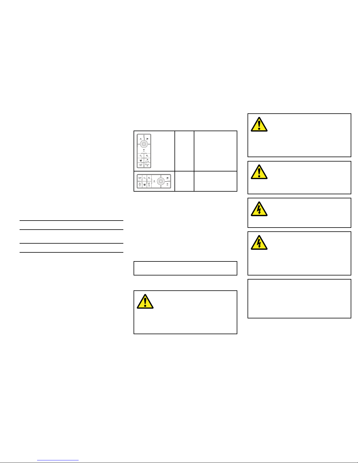
Althoughthewaterproofratingcapacityofthis
productmeetstheIPX6standard,waterintrusionand
subsequentequipmentfailuremayoccuriftheproduct
issubjectedtocommercialhigh-pressurewashing.
Raymarinewillnotwarrantproductssubjectedto
high-pressurewashing.
Disclaimer
Raymarinedoesnotwarrantthatthisproductis
error-freeorthatitiscompatiblewithproducts
manufacturedbyanypersonorentityotherthan
Raymarine.
Raymarineisnotresponsiblefordamagesorinjuries
causedbyyouruseorinabilitytousetheproduct,bythe
interactionoftheproductwithproductsmanufactured
byothers,orbyerrorsininformationutilizedbythe
productsuppliedbythirdparties.
EMCinstallationguidelines
Raymarineequipmentandaccessoriesconformto
theappropriateElectromagneticCompatibility(EMC)
regulations,tominimizeelectromagneticinterference
betweenequipmentandminimizetheeffectsuch
interferencecouldhaveontheperformanceofyour
system
CorrectinstallationisrequiredtoensurethatEMC
performanceisnotcompromised.
ForoptimumEMCperformancewerecommendthat
whereverpossible:
•Raymarineequipmentandcablesconnectedtoitare:
–Atleast1m(3ft)fromanyequipmenttransmitting
orcablescarryingradiosignalse.g.VHFradios,
cablesandantennas.InthecaseofSSBradios,
thedistanceshouldbeincreasedto7ft(2m).
–Morethan2m(7ft)fromthepathofaradarbeam.
Aradarbeamcannormallybeassumedtospread
20degreesaboveandbelowtheradiatingelement.
•Theproductissuppliedfromaseparatebatteryfrom
thatusedforenginestart.Thisisimportanttoprevent
erraticbehavioranddatalosswhichcanoccurifthe
enginestartdoesnothaveaseparatebattery.
•Raymarinespeciedcablesareused.
•Cablesarenotcutorextended,unlessdoingsois
detailedintheinstallationmanual.
Note:Whereconstraintsontheinstallation
preventanyoftheaboverecommendations,
alwaysensurethemaximumpossibleseparation
betweendifferentitemsofelectricalequipment,to
providethebestconditionsforEMCperformance
throughouttheinstallation
Declarationofconformity
RaymarineUKLtd.declaresthatthisproductis
compliantwiththeessentialrequirementsofEMC
directive2004/108/EC.
TheoriginalDeclarationofConformitycerticate
maybeviewedontherelevantproductpageat
www.raymarine.com.
Productdisposal
DisposeofthisproductinaccordancewiththeWEEE
Directive.
TheWasteElectricalandElectronicEquipment
(WEEE)Directiverequirestherecyclingofwaste
electricalandelectronicequipment.WhilsttheWEEE
DirectivedoesnotapplytosomeRaymarineproducts,
wesupportitspolicyandaskyoutobeawareofhow
todisposeofthisproduct.
Warrantyregistration
ToregisteryourRaymarineproductownership,please
visitwww.raymarine.comandregisteronline.
Itisimportantthatyouregisteryourproducttoreceive
fullwarrantybenets.Yourunitpackageincludesa
barcodelabelindicatingtheserialnumberoftheunit.
Youwillneedthisserialnumberwhenregisteringyour
productonline.Youshouldretainthelabelforfuture
reference.
IMOandSOLAS
Theequipmentdescribedwithinthisdocumentis
intendedforuseonleisuremarineboatsandworkboats
notcoveredbyInternationalMaritimeOrganization
(IMO)andSafetyofLifeatSea(SOLAS)Carriage
Regulations.
Technicalaccuracy
Tothebestofourknowledge,theinformationinthis
documentwascorrectatthetimeitwasproduced.
However,Raymarinecannotacceptliabilityforany
inaccuraciesoromissionsitmaycontain.Inaddition,
ourpolicyofcontinuousproductimprovementmay
changespecicationswithoutnotice.Asaresult,
Raymarinecannotacceptliabilityforanydifferences
betweentheproductandthisdocument.Please
checktheRaymarinewebsite(www.raymarine.com)to
ensureyouhavethemostup-to-dateversion(s)ofthe
documentationforyourproduct.
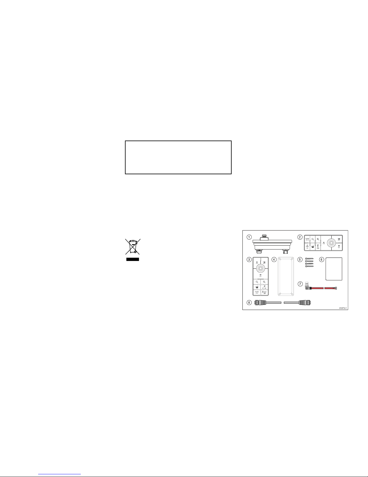
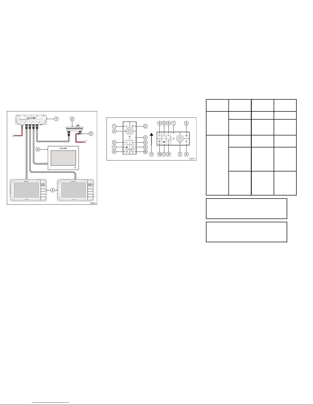
Partssupplied
Thepartssuppliedwiththekeypadareshownbelow.
D12712-1
1
3
8
7
456
2
1.Keypad.
2.Landscapekeypadmat.
3.Portraitkeypadmat.
4.Mountinggasket
5.4xmountingxings.
4RMK–9

6.Documentationpack.
7.Rightangledpowercable2m(6.6ft.).
8.RayNetnetworkcable2m(6.6ft.).
Locationandmounting
Keypaddimensions
A
B
C
D
E
F
D12726-1
A132.9mm(5.23in)
B119mm(4.7in)
C18.7mm(0.74in)
D8.5mm(0.33in)
E37mm(1.5in)
F90mm(3.5in.)
Flushmountingthekeypad
Forushmountingyoumustrebatethemounting
surfacetoaccommodatekeypad.
D12708-1
1.Checktheselectedlocationfortheunit.Aclear,
atareawithsuitableclearancebehindthepanel
isrequired.
2.Beforemodifyingthemountingsurface,refertothe
dimensionssuppliedinthisdocumenttoensure
thereisenoughspacefortheunitandallcables.
3.Fixthesuppliedmountingtemplatetotheselected
location,usingmaskingorself-adhesivetape.
4.Drill4holesasindicatedonthemountingtemplate
toacceptthexings.
5.Usingasuitableholesaw(thesizeandposition
isindicatedonthetemplate),makeaholeineach
cornerofthecut-outarea.
6.Usingasuitablesaw,cutalongtheinsideedgeofthe
rearcasingcut-outlineindicatedonthetemplate.
7.Usingarouterfollowtherebatecut-outlineonthe
templatetocutoutarebatewithadepthof8.5mm
(0.33in),toaccepttheunit.
8.Ensurethattheunittsintotheremovedareaand
thenremoveroughedges.
9.Placethesuppliedgasketontotherearofthe
keypad,ensuringthemountingholesarealigned.
10.Connectrelevantcables.
11.Placethekeypadintotherebateandsecureusing
thexingsprovided.
Note:Theappropriatetighteningtorqueanddrillbit
sizetousedependsonthethicknessofthemounting
surfaceandthetypeofmaterialitismadefrom.
Note:Thesuppliedgasketprovidesasealbetween
theunitandasuitablyatandstiffmountingsurface
orbinnacle.Thegasketshouldbeusedinall
installations.Itmayalsobenecessarytousea
marine-gradesealantifthemountingsurfaceor
binnacleisnotentirelyatandstifforhasarough
surfacenish.
Surfacemountingthekeypad
D12722-1
1.Checktheselectedlocationfortheunit.Aclear,
atareawithsuitableclearancebehindthepanel
isrequired.
2.Beforemodifyingthemountingsurface,refertothe
dimensionssuppliedinthisdocumenttoensure
thereisenoughspacefortheunitandcables.
3.Fixthesuppliedmountingtemplatetotheselected
location,usingmaskingorself-adhesivetape.
4.Drill4holesasindicatedonthemountingtemplate
toacceptthexings.
5.Usingasuitableholesaw,makeaholeineach
cornerofthecut-outarea.
6.Usingasuitablesaw,cutalongtheinsideedgeofthe
rearcasingcut-outlineindicatedonthetemplate.
7.Ensurethattheunittsintotheremovedareaand
thenremoveroughedges.
5

8.Placethesuppliedgasketontotherearofthe
keypad,ensuringthemountingholesarealigned.
9.Connectrelevantcables.
10.Secureusingthexingsprovided.
Note:Theappropriatetighteningtorqueanddrillbit
sizetousedependsonthethicknessofthemounting
surfaceandthetypeofmaterialitismadefrom.
Note:Thesuppliedgasketprovidesasealbetween
theunitandasuitablyatandstiffmountingsurface
orbinnacle.Thegasketshouldbeusedinall
installations.Itmayalsobenecessarytousea
marine-gradesealantifthemountingsurfaceor
binnacleisnotentirelyatandstifforhasarough
surfacenish.
Fittingthekeypadmat
Yourkeypadissuppliedwithaportraitandalandscape
keypadmat.
Youshouldtthekeypadmatwhichmatchesyour
chosenmountingorientation.
1.Ensurethekeypadmatisorientatedcorrectly.
2.Fitthekeypadmatintothekeypadsothatthe
keypadmattabsslideintotheholesinthekeypad,
asshownbelow.
D12 704 -2
3.Closetheoppositeendofthekeypadmatintothe
keypadensuringthattheendtabandallsidetabs
(shownbelow)clickrmlyintoplace.
D12705-2
Removingthekeypadmat
Thekeypadmatcanberemovedfromthekeypad
followingthestepsbelow.
D12713-2
123
Lockingtabsarelocatedatthepositionsshownabove.
Note:T akecareandensurethekeypadhousing
isnotdamaged
1.Usingathinbladedscrewdriverinsertthetipofthe
screwdriverintotherecessbetweentheedgeofthe
keypadmatandthekeypadhousingatlocation(1)
shownabove.
2.Gentlypushthescrewdriverawayanddownfrom
thekeypadmattoreleasethekeypadmattabs.
3.Repeatsteps1and2fortabsatlocations(2)and
(3).
4.Withall3tabsalongonesideofthekeypadfree
thekeypadmatshouldeasilycomeawayfromthe
keypad.
Connectionsoverview
D12728-1
1
2
1.Alternatepowerconnector.
2.Network/powerconnector.
Thealternatepowerconnectorisrequiredwhen
connectingtoanetworkwhichdoesnotsupportPower
overEthernetPoE.Thealternatepowerconnectormust
beconnecteddirectlytoapowersupply.
Note:Donotconnectthealternatepowerconnector
toaSeaT alkngnetwork.
Note:Onlyuseonepowersource.Thereisnoneed
toconnectthealternatepowerconnectorwhenthe
keypadisbeingsuppliedPoE.
Alternatepowerconnection
WhenthekeypadisnotsuppliedPoweroverEthernet
(PoE)thenthealternatepowerconnectionshouldbe
connecteddirectlytoa12Vdcor24Vdcpowersupply.
D12729-1
1
4
5
32
1.Keypad.
2.Rightangledpowercable.
3.Blacknegativewire.
4.Ground/shieldwire.
5.Redpositivewire.
6RMK–9

Warning:Productgrounding
Beforeapplyingpowertothisproduct,
ensureithasbeencorrectlygrounded,in
accordancewiththeinstructionsinthis
guide.
Grounding—Dedicateddrainwire
Thepowercablesuppliedwiththisproductincludesa
dedicatedshield(drain)wireforconnectiontoavessel's
RFgroundpoint.
ItisimportantthataneffectiveRFgroundisconnected
tothesystem.Asinglegroundpointshouldbeusedfor
allequipment.Theunitcanbegroundedbyconnecting
theshield(drain)wireofthepowercabletothevessel's
RFgroundpoint.OnvesselswithoutanRFground
systemtheshield(drain)wireshouldbeconnected
directlytothenegativebatteryterminal.
Thedcpowersystemshouldbeeither:
•Negativegrounded,withthenegativebatteryterminal
connectedtothevessel'sground.
•Floating,withneitherbatteryterminalconnectedto
thevessel'sground
Warning:Positiveground
systems
Donotconnectthisunittoasystemwhich
haspositivegrounding.
Keypadconnection
Thekeypadcanbeconnecteddirectlytoamultifunction
display’snetworkconnectororviaanetworkswitch.
Multiplekeypadscanbeconnectedtoasystem.Each
keypadcanbeusedtocontrolupto4multifunction
displays.IfthenetworkdoesnotprovidePowerover
Ethernet(PoE)thenthekeypadmustbepowered
separately.
Directconnection—gSSeriesmultifunctiondisplay
D12702-2
2
1
1.gSSeriesmultifunctiondisplay.
2.Keypad.
WhenconnectingthekeypaddirectlytoagSSeries
multifunctiondisplaythekeypadissuppliedwithPoE,
fromthemultifunctiondisplay.
Directconnection—Raymarinemultifunction
display
D12694-2
2
3
1
1.Multifunctiondisplay.
2.Keypad.
3.Rightangledpowercable.
WhenconnectingthekeypaddirectlytoaNewaSeries,
NewcSeriesorNeweSeriesmultifunctiondisplaythe
keypadisnotsuppliedwithPoE,andsorequirespower
usingthealternatepowerconnector.
Networkconnection—gSSeriesmultifunction
displays
D12709-2
2
1
3 3
1.gSSeriesmultifunctiondisplay(supplyingPoEto
thekeypad).
2.Keypad.
3.NetworkedgSSeriesmultifunctiondisplays.
WhenconnectingthekeypadtoagSSeries
multifunctiondisplaynetworkthekeypadissupplied
withPoE.
7

Networkconnection—Raymarinemultifunction
displays
D12697-3
4
12
3
4
1.Networkswitch.
2.Keypad.
3.Rightangledpowercable.
4.Networkedmultifunctiondisplays.
Whenconnectingthekeypadtoanetworkswitchthe
keypadrequiresaseparatepowersupplyusingthe
alternatepowerconnector.
Onceconnectedthekeypadmustbepairedwiththe
eachmultifunctiondisplayyouwanttocontrolusing
thekeypad.
Keypadcontrols
Connectingthekeypadallowsyoutocontrolyour
multifunctiondisplayremotely.
D1271 1-1
1
3
5
7
9
2
4
6
8
10
1011783 4
9 5 6 1 2
1.Home—presstoreturntothehomescreen.
2.Menu—accessesmenus.Pressagaintoclose
menus.
3.UniControl—providesarotarycontrolanda
joystickwithanOKpushbuttonforusingmenus
andapplications.
4.Back—presstoreturntoapreviousmenuor
dialoglevel.
5.RangeOut—presstorangeout.
6.RangeIn—presstorangein.
7.SwitchActive—presstoswitchtheactivepane,
ortoswitchtheactivemultifunctiondisplay(in
multipledisplaysystems).
8.WPT/MOB—pressandreleasetoaccessthe
waypointoptions.Pressagaintoplaceawaypoint.
PressandholdtoplaceaManOverboard(MOB)
markeratyourcurrentposition.
9.Standby(Auto)—presstodisengageintegrated
autopilot,pressandholdtoactivateAutomodeon
integratedautopilot.
10.Power—seetablebelow:
Congura-
tion
Display
State
Momentary
press
Pressand
hold
OffPoweron*—
1
Multifunction
displayOnOpen
shortcuts
page
Powerdown
Alldisplays
Off
Poweronall
displays*
—
Alldisplays
On
Open
shortcuts
pageon
active
display
Powerdown
alldisplays
Multiple
multifunction
displays
1DisplayOn
and1display
Off
Open
shortcuts
pageon
active
display
Power
downactive
display
Note:*OnlyapplicabletogSSeriesdisplays.
NewaSeries,NewcSeriesandNeweSeries
displayscannotbepoweredonusingthe
keypad.
Note:Inamultipledisplaycongurationwhere
displaysareindifferentstatesthedisplaysthat
areturnedoffcanonlybeturnedonusingthe
powerbuttononthedisplay.
11.JoystickUpdirection.
Pairingthekeypad
Thekeypadcancontrol1ormoremultifunction
displays.Multiplekeypadscanbeconnectedtoa
system.Eachkeypadcanbepairedwithupto4
multifunctiondisplays.
Withthekeypadconnectedtothemultifunctiondisplay:
1.SelectExternalKeypadfromtheExternalDevices
menu:homescreen→Set-up→SystemSettings
→ExternalDevices→ExternalKeypad.
8RMK–9

2.SelectPairKeypad.
3.Pressanybuttonontheexternalkeypad.
4.Fromthepop-upmessageselecttheorientationof
thekeypad.
Eitherlandscapeorportraitorientationsare
available.
Thekeypadisnowpaired.
Switchingtheactivepaneordisplayusingthe
keypad
TheSwitchActivebuttonisusedtoswitchtheactive
paneonamultiapplicationpageand/ortoswitchthe
activedisplay.
Withmultipledisplaysconnectedand/oramultiple
applicationpagedisplayed:
Cyclesequence
4
1235
D12703-1
1.PresstheSwitchActivebuttontoenterswitch
mode.
2.UsetheRotaryControltocyclethroughthe
availablepanesand/ordisplays.
Thekeypadwillcyclethroughdisplaysintheorder
inwhichtheywerepaired.Onmultiapplication
pagestheRangebuttonscanbeusedtoswitchthe
activeapplicationbetweenfullandsplitscreen.
3.PresstheBackbuttonortheSwitchActivebutton
toexitswitchmode.
Unpairingthekeypad
Thekeypadcanbeunpairedfromanindividualdisplay.
1.SelectExternalKeypadfromtheExternalDevices
menu:homescreen→Set-up→SystemSettings
→ExternalDevices→ExternalKeypad.
2.SelectClearPairings.
3.SelectYestounpairthekeypadwiththedisplay.
Determiningtheactivedisplay
Youcandeterminewhichdisplayiscurrentlyactive.
1.PresstheSwitchActivebutton.
Theswitcherpop-upisdisplayedonthescreenor
panethatisactive.
2.PresstheSwitchActivebuttonagaintoclosethe
switcherpop-up.
Theactivedisplayremainsthesame.
Raymarinecustomersupport
Raymarineprovidesacomprehensivecustomersupport
service.Youcancontactcustomersupportthroughthe
Raymarinewebsite,telephoneande-mail.Ifyouare
unabletoresolveaproblem,pleaseuseanyofthese
facilitiestoobtainadditionalhelp.
Websupport
Pleasevisitthecustomersupportareaofourwebsiteat:
www.raymarine.com
ThiscontainsFrequentlyAskedQuestions,servicing
information,e-mailaccesstotheRaymarineT echnical
SupportDepartmentanddetailsofworldwide
Raymarineagents.
Telephoneande-mailsupport
IntheUSA:
•Tel:+16033247900
•TollFree:+18005395539
•E-mail:[email protected]
IntheUK,Europe,andtheMiddleEast:
•Tel:+44(0)1329246777
•E-mail:[email protected]
InSoutheastAsiaandAustralia:
•Tel:+61(0)294794800
•E-mail:[email protected]
Productinformation
Ifyouneedtorequestservice,pleasehavethefollowing
informationtohand:
•Productname.
•Productidentity.
•Serialnumber.
•Softwareapplicationversion.
•Systemdiagrams.
Youcanobtainthisproductinformationusingthemenus
withinyourproduct.
Technicalspecication
Powerspecication
PoEclassClass1
Nominalsupply
voltage
12/24Vdc
Operating
voltagerange
10.8Vdcto31.2Vdc
Power
consumption
3.84W
Environmentalspecication
Operating
temperature
-25ºCto+55ºC(-13ºFto131ºF)
Storage
temperature
-30ºCto+70ºC(-22ºFto158ºF)
RelativehumidityMaximum75%
WaterproofratingIPX6
9

Wiredconnections
Network/power1xRayNetconnector
•gSSeries—1000Mb/splusPoE.
•a,c,eSeries—100Mb/s.
Alternatepower1xPowerconnector.
Keypadspares
ItemPartnumber
Keypadmatspare(includes
landscapeandportraitkeypad
mat.)
R70185
RightangledpowercableA06070
Networkcables
RayNettoRayNetcables
CablePartnumber
400mm(1.3ft)RayNetto
RayNetcable(female)
A80161
2m(6.56ft)RayNettoRayNet
cable(female)
A62361
5m(16.4ft)RayNettoRayNet
cable(female)
A80005
10m(32.8ft)RayNetto
RayNetcable(female)
A62362
20m(65.6ft)RayNetto
RayNetcable(female)
A80006
50mm(1.97in)RayNetto
RayNetcable(male)
A80162
RayNetright-angledcouplerA80262
RayNetcablepuller5-packR70014
RayNettoRJ45SeaTalkhsadaptercables
CablePartnumber
1m(3.28ft)RayNettoRJ45
SeaTalkhscable
A62360
3m(9.84ft)RayNettoRJ45
SeaTalkhscable
A80151
10m(32.8ft)RayNettoRJ45
SeaTalkhscable
A80159
400mm(1.3ft)RayNetto
RJ45SeaTalkhs(female)
cable
A80160
10RMK–9


www.ra ym a rin e .c o m
Other manuals for RMK-9
1
Table of contents
Other Raymarine Car Navigation System manuals