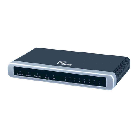
RayTalk RA-490 User manual


2
RA-490

3
Copyright Notice
Copyright © All rights reserved. No part of this document may be copied, reproduced, or transmitted by
any means, for any purpose without prior written permission.
Protected by patent.
Disclaimer
We shall not be liable for technical or editorial errors or omissions contained herein; nor for incidental or
consequential damages resulting from furnishing this material, or the performance or use of this
product. We reserve the right to change the product specification without notice. Information in this
document may change without notice.
Trademarks
Microsoft Win98, Windows 2000 and WinXP are registered trademarks of Microsoft Corporation.
General:All other brand and product names mentioned herein may be registered trademarks of their
respective owners. Customers should ensure that their use of this product does not infringe upon any
patent rights. Trademarks mentioned in this publication are used for identification purposes only and
are properties of their respective companies.

4
Table of Contents
1. Introduction...................................................................................................................................... 6
1-1 Package Contents ......................................................................................................................... 6
1-2 Features ........................................................................................................................................ 7
1-3 Precautions.................................................................................................................................... 7
1-4 Outlook .......................................................................................................................................... 8
1-4-1 Top Panel .......................................................................................................................... 8
1-4-2 Rear Panel ........................................................................................................................10
1-5 Technical Specifications.................................................................................................................11
1-5-1 Hardware Specifications....................................................................................................11
1-5-2 Software Specifications ...................................................................................................12
2. Installation...................................................................................................................................... 14
2-1 Wall-mounting.............................................................................................................................. 14
2-2 Connecting the Antennas ............................................................................................................ 15
2-3 Installation Requirements ............................................................................................................ 15
2-4 Getting Start................................................................................................................................. 17
2-5 How expanding your Account Generator Printer’s distance ........................................................ 18
2-6 POE Application........................................................................................................................... 19
3. Configuring the Wireless Subscriber Gateway .......................................................................... 20
3-1 Setting Wizard ............................................................................................................................. 20
3-2 Advanced Setup .......................................................................................................................... 44
3-2-1 System ............................................................................................................................ 45
3-2-2 WAN/LAN ........................................................................................................................ 49
3-2-3 Server.............................................................................................................................. 55
3-2-4 Authentication ................................................................................................................. 57
3-2-5 RADIUS Authentication ................................................................................................... 59
3-2-6 Billing............................................................................................................................... 62
3-2-7 Accounting ...................................................................................................................... 68
3-2-8 Credit Card...................................................................................................................... 81
3-2-9 Keypad ............................................................................................................................ 88
3-2-10 Customization ................................................................................................................. 96
3-2-11 Pass Through................................................................................................................ 122
3-2-12 Filtering ......................................................................................................................... 124
3-2-13 Share............................................................................................................................. 126
3-2-14 Portal Page.................................................................................................................... 127
3-2-15 Advertisement ............................................................................................................... 128
3-2-16 Walled Garden .............................................................................................................. 129

5
3-2-17 DDNS ............................................................................................................................ 131
3-2-18 LAN Devices ................................................................................................................. 133
3-2-19 Syslog ........................................................................................................................... 135
3-2-20 Session Trace ............................................................................................................... 142
3-2-21 SNMP............................................................................................................................ 143
3-2-22 Wireless ........................................................................................................................ 145
3-3 System Status............................................................................................................................ 149
3-3-1 System .......................................................................................................................... 150
3-3-2 Account List................................................................................................................... 152
3-3-3 Account Log .................................................................................................................. 153
3-3-4 Current User.................................................................................................................. 155
3-3-5 DHCP Client.................................................................................................................. 155
3-3-6 Session List................................................................................................................... 155
3-3-7 LAN Devices ................................................................................................................. 156
3-4 System Tools ............................................................................................................................. 156
3-4-1 Configuration................................................................................................................. 157
3-4-2 Firmware Upgrade .........................................................................................................158
3-4-3 System Account ............................................................................................................160
3-4-4 SSL Certificate .............................................................................................................. 164
3-4-5 Ping Command ..............................................................................................................165
3-4-6 Restart........................................................................................................................... 165
3-4-7 Logout ........................................................................................................................... 165
3-5 FAQ & Glossary......................................................................................................................... 166
3-5-1 Frequently Asked Questions ......................................................................................... 166
3-5-2 Glossary of Terms ......................................................................................................... 167
Appendix A. RJ-45 Connector Description ........................................................................................ 168

6
1. Introduction
The RA-490 Wireless Subscriber Gateway is a compact intelligent gateway integrated with a four-port
port-based VLAN switch. It provides Plug’ Play Internet access, advanced security and network
management.
The RA-490 Wireless Subscriber Gateway is designed for service providers, system integrator or
hotspot venue operator without backend-RADIUS-Server to have integrated solution for rapid
deployment, which can start hotspot service quickly and easily and enhance service performance.
The Wireless Subscriber Gateway is an ideal solution for hotel lobbies, coffee bars, airport lounges,
conference facilities and other sites that commonly host business travelers, and offers instant
high-speed Internet connections. With its IP Plug and Play technology, it accepts any client
configuration login, when client open browser the Wireless Subscriber Gateway immediately
recognizes new end-user and redirects their browser to customized Web pages. There’s no need for
end-user to change any of their default network (Static IP), e-mail (SMTP Server behind firewall), or
browser settings (HTTP Proxy) or load any special software to access hotspot service. It’s completely
Plug’ Play with any browser.
1-1 Package Contents
Please inspect your package. The following items should be included:
One RA-490 Wireless Subscriber Gateway
!Two antennas
!One AC Power Adapter for Wireless Subscriber Gateway
!One CD containing User’s Manual and MIB file
!Two screws for wall-mount
!One UTP Ethernet/Fast Ethernet cable (Cat.5 Twisted-pair)
One Account Generator Printer
!One AC Power Adapter for mini account generator printer
!One RJ-11 to DB9 male connector cable
!One Account Generator Printer User’s Guide
If any of the above items are damaged or missing, please contact your dealer immediately.

7
1-2 Features
!Wireless data rates up to 54Mbps
!Supports 100 Simultaneous Users
!IP Plug and Play (iPnP)
!Comprehensive security
64/128-bit WEP encryption
WPA encryption
IP/URL filtering
!Intelligent Management
!Built-in AAA (Authentication/Accounting/Authorization) and Billing mechanism
Note: The "PnP" Function only can be used with TCP/IP-based Network.
1-3 Precautions
!Never remove or open the cover. You may suffer serious injury if you touch these parts.
!Never install the system in the wet locations.
!Use only the original fitting AC power adapter otherwise there is a danger of severe electrical shock.
!Avoid exposing the Wireless Subscriber Gateway to direct sunlight or another heat source.
!Choose a well-ventilated area to position your Wireless Subscriber Gateway.

8
1-4 Outlook
Figure 1-1 RA-490 Wireless Subscriber Gateway Outlook
1-4-1 Top Panel
The top panel of the Wireless Subscriber Gateway is shown below.
Figure 1-2 RA-490 Wireless Subscriber Gateway Top Panel

9
Figure 1-3 LEDs
LEDs Indication
LED State Description
Off The Wireless Subscriber Gateway is not receiving electrical power.PWR
Green The Wireless Subscriber Gateway is receiving electrical power.
Off The Wireless Subscriber Gateway status is defective.
Green The Wireless Subscriber Gateway status is complete.
SYS
Green (Blinking) During firmware upgrades, this system LED will blink.
Off Port has not established any network connection.
Green A port has established a valid 10/100Mbps network connection.
WAN
Green (Blinking) 10/100Mbps traffic is traversing the port.
Off Port has not established any network connection.
Green A port has established a valid 10/100Mbps network connection.
LAN-1~
LAN-4
Green (Blinking) 10/100Mbps traffic is traversing the port.
Off The Wireless is not ready.
Green The Wireless Subscriber Gateway has established a valid wireless
connection.
WLAN
Green (Blinking) The Wireless connection is active.

10
1-4-2 Rear Panel
The rear panel of the Wireless Subscriber Gateway is shown below.
Figure 1-4 RA-490 Wireless Subscriber Gateway Rear Panel
1. Printer: Used to connect the Account Generator Printer.
2. LAN (1-4):
The rear panel supports four auto-sensing RJ-45 ports and all ports can be auto-switched to MDI-II
connections. The LAN ports used for linking hosts or other network devices. The individual port can be
either connected to 100BaseTX networks or 10BaseT networks. When connecting to a 100BaseTX
network, the ports operate at 100Mbps in half-duplex mode or 200Mbps in full-duplex mode. When
connecting to a 10BaseT network, the ports operate at 10Mbps in half-duplex mode or 20Mbps in
full-duplex mode.
3. WAN: One Ethernet port used for linking xDSL or Cable Modem.
4. Reset Button:
The Wireless Subscriber Gateway has a reset button at the rear panel of the device. Use this function
to reset the system back to factory defaults.
5. Power Jack: Used to connect the external power supply with the Wireless Subscriber Gateway.

11
1-5 Technical Specifications
1-5-1 Hardware Specifications
Network Specification
IEE802.3 10BaseT Ethernet
IEE802.3u 100BaseTX Fast Ethernet
IEE802.11g Wireless LAN
IEEE802.3af Power o ver Ethernet
ANSI/IEEE 802.3 NWay auto-negotiation
Wi-Fi Compatible
Connectors
One Printer Port (1 DB9 DTE male connector for Account Generator Printer)
Four LAN Ports (10BaseT/100BaseTX Auto cross-over)
One WAN Port (10BaseT/100BaseTX Auto cross-over)
Encryption
WEP (Wired Equivalent Privacy) 64/128-bit RC4
WPA (Wi-Fi Protected Access)
External Antenna Type
2dBi (Max) Dual detachable diversity antenna with reverse SMA
LED Indicators
One POWER LED
One WAN 10/100M Link/Activity LED
Four LAN 10M/100M Link/Activity LEDs
One Wireless Link/Activity LED
One System LED
Power Requirement
External Power Adapter
Input: 100-240 VAC, 50/60 Hz
Output: 5V, 2A
Environment Conditions
Operating Temperature: 0 to 50°C
Storage Temperature: -10 to 60°C
Operating Humidity: 10~80% non-condensing
Storage Humidity: 10% to 90% non-condensing

12
Certifications
FCC part 15 Class B, CE, CSA, VCCI Class B, TELEC, CE / R&TTE, C-Tick, JATE
Dimension
Size: 242 (L) x 130.5 (W) x 112.6 (H) mm
Weight: About 420g (Net)
Mounting
Desktop, Wall mounted
1-5-2 Software Specifications
Networking
•IEEE802.3 10BaseT Ethernet
•IEEE802.3u 100BaseTX Fast Ethernet
•IEEE802.3af Power o ver Ethernet
•IEEE802.11b Wireless LAN
•IEEE802.11g Wireless LAN
•Supports 100 Simultaneous Users
•IP Plug and Play (iPnP)
•HTTP Proxy Support
•WEP Data Encryption
•SMTP Server Redirection
•DHCP Server
•DHCP Relay
•Static IP WAN Client
•DHCP WAN Client
•PPPoE WAN Client
•PPTP WAN Client
•NAT
•IP Routing
•NTP (Network Time Protocol) Support
•IP Multicast support
Marketing Cooperation
•Advertisement URL link
•Walled garden
•Customize Login Page
•Portal Page

13
AAA/Billing
•Built-in Authentication
•Web-based Login Page Authentication
•Exclusive Printer Accounting without PC operating
•Web-based Accounting
•Flexible Billing Profiles and Price Plan
•Flexible Billing Mechanism (Pre-Paid and Post-Paid)
•Flexible Time Mechanism (Time to Finish and Accumulation)
•Credit Card Support (Authorize.net and iValidate.net)
•External PS/2 Keypad Support
Security
•Layer 2 Isolation
•SSL Login Page
•SSL Administration
•VPN Pass through (IPSec/PPTP/L2TP)
•Customize SSL Certificate
•Pass through Destination IP/URL
•Pass through Source IP/MAC
•Restricted Destination Filtering IP/URL
•Share LAN Resources
Management
•Administrator/Super Subscriber/Account Manager Management Access
•Remote Browser-based Configuration and management
•Authorized remote management (Access Control List)
•Firmware Upgrade via HTTP/TFTP
•Scheduled Firmware Upgrade
•Backup/Restore/Factory Default Setting
•LAN Device Management
•Dynamic DNS
•System Information Table
•Real-time Current User List/ DHCP Clients List/ Session List/ Account List
•Syslog
•Status Report (Daily/Monthly/System/Network)

14
2. Installation
The followings are instructions for setting up the Wireless Subscriber Gateway. Refer to the illustration
and follow the simple steps below to quickly install your Wireless Subscriber Gateway.
2-1 Wall-Mounting
The Wireless Subscriber Gateway can be wall-mounted on a wall by applying the two mounting
brackets on screws.
Figure 2-1 Wall-Mounting Bracket - Bottom of RA-490 Wireless Subscriber Gateway
Please refer to the following instructions for mounting a Wireless Subscriber Gateway on a wall or other
surface.
1. Install two screws on a wall according to the relative positions shown below.
Figure 2-2
2. Hang Wireless Subscriber Gateway on the wall by sliding the two screws in the mounting brackets.
Note: If the screws are not properly anchored, the strain of the cables connected to the Wireless
Subscriber Gateway rear panel connectors could pull out the Wireless Subscriber Gateway from
the wall.

15
2-2 Connecting the Antennas
The Wireless Subscriber Gateway provides two antenna connectors on the rear of the unit.
Figure 2-3 Antenna Connectors
2-3 Installation Requirements
Before installing the Wireless Subscriber Gateway, make sure your network meets the following
requirements.
System Requirements
The Wireless Subscriber Gateway requires one of the following types of software:
!Windows 98 Second Edition/NT/2000/XP
!Red Hat Linux 7.3 or later version
!MAC OS X 10.2.4 or later version
!Any TCP/IP-enabled systems like Mac OS and UNIX (TCP/IP protocol installed)
!Standard phone line for xDSL modem
Or
Coaxial cable for Cable modem
!Web Browser Software (Microsoft I.E 5.0 or later version or Netscape Navigator 5.0 or later
version)
!One computer with an installed 10Mbps, 100Mbps or 10/100Mbps Ethernet card
!UTP network Cable with a RJ-45 connection (Package contents)
Note: Prepare twisted-pair cables with RJ-45 plugs. Use Cat.5 cable for all connections. Make sure
each cable not exceed 328 feet (Approximately 100 meters).

16
ISP Requirements
Verify whether your ISP use fixed or dynamic IP. If it is a fixed IP, be sure to get the IP from your ISP.
For dynamic IP, which is mostly used, the PC will get the IP automatically whenever it hooks up on
the modem.
Dynamic IP
!Dynamic IP Setting
Fixed IP
!Your fixed IP address for the Wireless Subscriber Gateway
!Your subnet mask for the Wireless Subscriber Gateway
!Your default gateway IP address
!Your DNS IP address
PPPoE
!Your user name from your ISP
!Your password from your ISP
PPTP
!PPTP Server IP Address from your ISP
!PPTP Local IP address from your ISP.
!PPTP Local IP subnet mask from your ISP.
!Your user name from your ISP
!Your password from your ISP
Your PC Requirements
The Static IP settings for the PC
!Your PC’s fixed IP address
!Your PC’s subnet mask
!Your PC’s default gateway IP address
!Your PC’s primary DNS IP address
Note:
1. The gateway’s default IP address setting is “10.59.1.1”.
2. The gateway’s default subnet mask setting is “255.0.0.0”.
The Dynamic IP settings for the PC
We recommend that you leave your IP settings as automatically assigned. By default, the Wireless
Subscriber Gateway is a DHCP server, and it will give your PC the necessary IP settings.

17
2-4 Getting Start
1. Place the Wireless Subscriber Gateway and Account Generator Printer on a flat work surface.
2. Connect the DB9 connector of printer cable to the Wireless Subscriber Gateway’s device port at the
rear panel of the device.
3. Connect the other end of the printer cable to the Account Generator Printer’s RJ11 port at the rear
panel of the device. Check that the account generator printer status LED lights.
4. Ensure that your modem and computer are both switched on.
5. Use the supplied cable to connect the Wireless Subscriber Gateway's WAN port to the modem.
Check that the Cable/xDSL Status LED lights.
6. Connect your computer to one of the 10/100 LAN ports on the Wireless Subscriber Gateway. Check
that the LAN Port Status LED lights.
7. Configure the further parameters via a Web browser.
Figure 2-4 RA-490 Wireless Subscriber Gateway Connection

18
2-5 How expanding your Account Generator Printer’s distance
1. Place the Wireless Subscriber Gateway and Account Generator Printer on a flat work surface.
2. Connect the DB9 connector of printer cable to the Wireless Subscriber Gateway’s device port at the
rear panel of the device.
3. Connect the other end of the printer cable to the telephone jack’s RJ11 port.
4. Use the phone line (2-pair cable with RJ11 plugs) to connect the Account Generator Printer’s RJ11
port at the rear panel of the device.
5. Connect the other end of the phone line to the telephone jack’s RJ11 port. Check that the account
generator printer status LED lights.
6. Done.
Figure 2-5 Account Generator Printer Connection
Note: By using the phone line you can increase the maximum distance up to 15 meter.
Telephone surface jack

19
2-6 POE (Power over Ethernet) Application
Figure 2-6 POE Connection
Note: To use the RA-490’s POE feature, follow the instructions for your specific POE device.

20
3. Configuring the Wireless Subscriber Gateway
3-1 Setting Wizard
Step 1: Start your browser, and then enter the factory default IP address 10.59.1.1 in your browser’s
location box. Press Enter.
Figure 3-1 RA-490 Web Browser Location Field (Factory Default)
Step 2: The Wireless Subscriber Gateway configuration tools menu will appear. In the Username and
Password field, type the factory default user name admin and password admin and click
Login. If you are first time setting the system, the wizard setup screen will appear. You will be
guided, step-by-step, through a basic setup procedure.
Figure 3-2 Configuration Tools Menu
Figure 3-3 Wizard Setup Screen
Username: admin
Password: admin
Table of contents
Other RayTalk Gateway manuals

