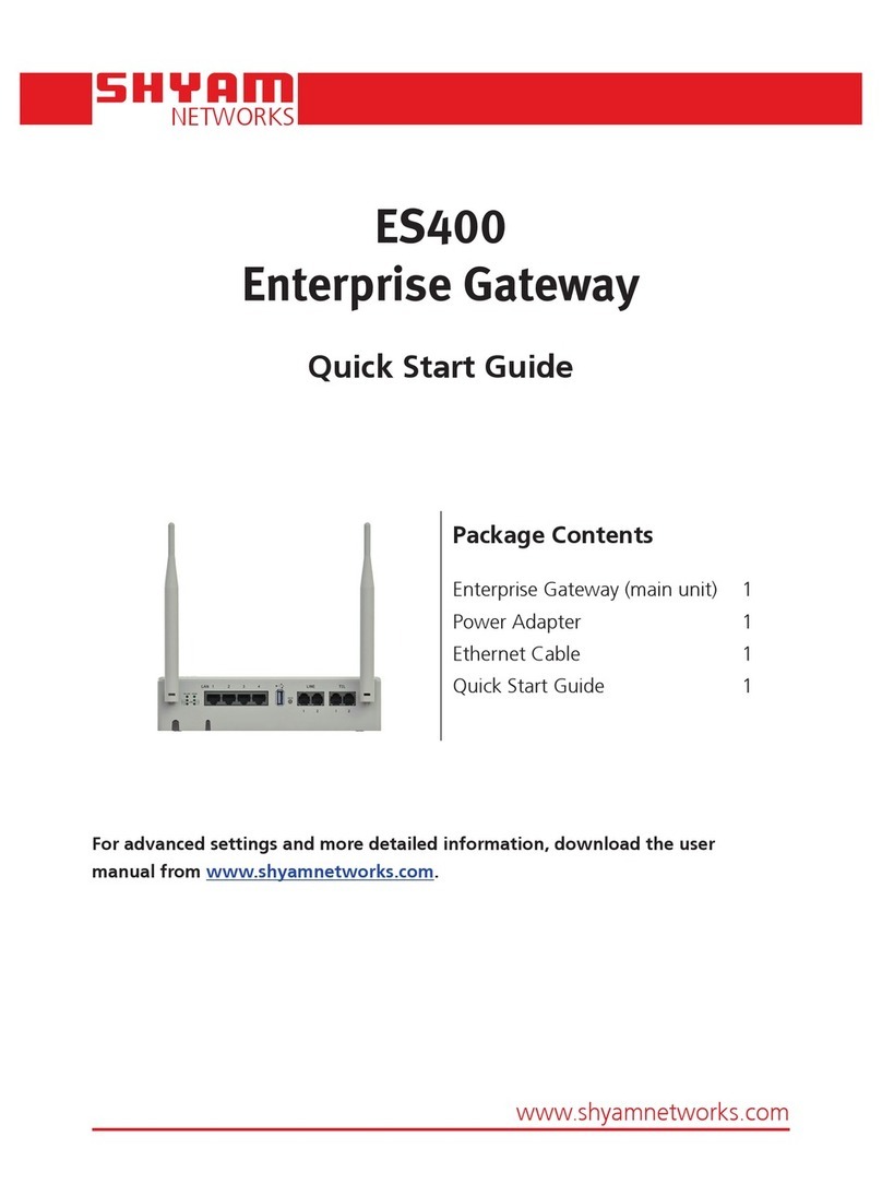
INTELCO INTD0909 Instruction manual

GSM Gateway INTD0909
voice / data
INTD0909
www.pelekis.tech
Please read carefully the instructions in order to
get all the benefits of this device.
Page 2 General Description - Specification
Page 3 Wiring-Connection
Page 4 Quick-Start Setup
Page 5 LEDs Indication
Page 6 SMS programming codes
Page 7 Extra Information - Technical support
GSM Gateway
voice / data
Rev. 1.01 March 2016
Quick-Start Manual

INTELCO ELECTRONICS 2ISO9001/2015 Rev. 1.01 March 2016
The GSM gateway INTD0909 is an electronic device which can be used as a
stand alone voice & data communication gateway for almost any remote use. It is
specially
designed for elevator installations and combined with INTD0900, it unlocks many
features for reliable, robust and secure emergency GSM/Phone line calls.
The GSM gateway INTD0909 operates with 230V AC mains input or from a
backup battery (SLA type) 6,3V. If mains power fails, it switches to backup battery
operation and it can fully operate for up to 6 hour. The device does real time
battery charging/conditioning/maintaining and RF antenna signal strength
monitoring.
Combined with our external I/O expansion card, the INTD0909 can be trans-
formed as an Input/output wireless remote monitoring and controlling device!
Caution : The installation and settings of the device, must be done by a qualified
person.
General Description:
Specifications:
Power supply 230V AC 50Hz
Power consumption 3.5W continuous, all features on, all led on
Network bands GSM 850/900/1800/1900MHz
Operation temperature 0-60°C
Operation humidity 10-80% (non condensing)
On board battery type Sealed Lead Acid GEL type 6V/1.3Ah
Battery charger type Trickle charging with MCU monitoring
SIM card type Standard, 3V
On board connectivity 2 optically isolated inputs
2 relay outputs
Optional add on card serially controlled ,for ex-
tending up to 8 inputs / 8 Outputs
Phone Line connection Standard RJ-45 jack
Ext. Line connection Standard RJ-45 jack
Dimensions (External) 60 x 210 x 145 mm (H x W x D)
Weight (Total/w Battery) 1Kg

INTELCO ELECTRONICS 3ISO9001/2015 Rev. 1.01 March 2016
Connect the antenna at the terminal to the side of the box. Make sure for good
locking
Connect at the terminal PHONE of the device the telephone which will be used
(simple telephone or emergency telephone).
Install the SIM Card to SIM holder. Make sure that you have deactivated the
PIN number first.
Connect the 2 cables (Black and Red) to the right poles of the battery.
Connect the power cable to the terminal and plug it to the 230V AC.
Make a short circuit at the jumper “RESET” beside of the terminal BAT.
Wiring-Connection:
N
L
NC
Power
Outputs
Inputs
R1
R1
C1
R2
C2
R1
C1
C2
R2
INTELPHONE
SIM Card
RESET
Fuse
LED Indication
Line
Battery
Network
signal
strength
Net Status
AC
Battery (6,3V)
External

INTELCO ELECTRONICS 4ISO9001/2015 Rev. 1.01 March 2016
Quick-Start Setup:
In order to startup the GSM Gateway device, please power up the device and then
short RESET pins by placing the RESET jumper. At startup of the device one short
buzz sound.
Device makes a quick check on AC power supply. If there is no AC power, device
will start up, powered from Battery if connected and it is good charged. While de-
vice performs the action above all onboard leds are keep blinking every 500 ms .
After 4-5 sec device will start seeking for network to connect according to provider
of the applied SIM card and while this action S1,S2 and S3 leds are blinking and
Network led is blinking every 500 ms indicating that no network found till now. If
Network can not be found in a specific period of time, device timeout the process.
If Network did not found, device will work with “NO SIM Card detect” and can only
make outgoings call to (112) . If Network is approached device will work with “SIM
Card detect” and fully functional.
When S1,S2 and S3 leds stop blinking and Network led blink every 3 seconds then
onboard buzzer will buzz 2 times with short pause between.
Double buzzing sound let the user know that the startup process is just finished and
device is READY FOR USE, with every feature available to the user according the
status of network connection.
Functions with “SIM Card detected” :
Voice Ready
SMS Ready
Data Ready (Not Available)
Battery check
Functions with “SIM Card not detected” :
Limited Voice Ready ( International Emergency Number (112))
Battery check
STEP 1
STEP 2
STEP 3
STEP 4

INTELCO ELECTRONICS 5ISO9001/2015 Rev. 1.01 March 2016
LEDs Indication
LED status Description
ON AC power presents
OFF AC power does not presents
AC Led
LED status Description
ON Hook off
OFF Hook on
Blink* (2 on / 4 off) Ringing
Blink* (0,5 on / 0,5 off) Connection established
LINE Led
LED status Description
Blink* (0,5 on / 0,5 off) Network disconnected
Blink* (0,5 on / 3 off) Network connected
NET Led
Description
S1 S2 S3
0 0 0 Signal not Detectable or < -115dBm
1 0 0 Signal < - 91dBm (Weak)
1 1 0 Signal < - 71dBm (Good)
1 1 1 Signal < - 51dBm (Excellent)
LED status
Signal Leds
*Blink is in seconds.
LED status Description
ON Battery is full charged
Blink* (3 on / 1 off) Battery over 70%.
Blink* (1 on / 3 off) Battery over 50%
OFF Battery not connected
BAT Leds

INTELCO ELECTRONICS 6ISO9001/2015 Rev. 1.01 March 2016
SMS Programming Table
Command Description Edit - Delete Ask
USER AUTHORIZED
1 Calling number (4) #0000#1#...n...,_,...n2..,...n3…*
Example : n =00302102323345 #0000#1#?
2 Low battery call number #0000#2#6974587393*
Delete : #0000#2#_* #0000#2#?
3 User password #0000#3#1E5D* -
4 Buzzer function #0000#4#0*(OFF)
#0000#4#1* (ON) #0000#4#?
5 Missed call function #0000#5#0*(OFF)
#0000#5#1* (ON) #0000#5#?
6 Ask monitor - #0000#6#?
7
Outputs-Relays
R1
R2
R1,R2
#0000#7#R1=1✶,R1=0✶
#0000#7#R2=1✶,R2=0✶
#0000#7#R1=0,R2=0✶
#0000#7#R1=1,R2=1✶
#0000#7#?
8 Inputs-Optocouplers #0000#8#0*(AUTO OFF)
#0000#8#1*(AUTO ON) #0000#8#?
ADMIN AUTHORIZED
20 Admin password #1111#20#1E5D* -
21 Auto-run number #1111#21#6974587393*
Delete : #1111#21#_* #1111#21#?
22 Voice function #1111#22#0* (OFF)
#1111#22#1* (ON) -
23 Ask IMEI - #1111#23#?
24 SIM Card notifications #1111#24#0* (OFF)
#1111#24#1* (ON) -
Note:
‘ _ ’ : Variable reset to 0, delete.
‘ * ’ : Save or Act on variable.
‘ ? ’ : Ask the content of variable.
‘ # ’ : Change parameter field.
‘ , ’ : Change scope of variable if more than one Ex.(#0000#7#R1=1,r8:0,r7=0,r1=0* )

INTELCO ELECTRONICS 7ISO9001/2015 Rev. 1.01 March 2016
Extra Information
For any extra information about installation or the operation mode of the device,
please refer to the GSM Reference Manual which is uploaded at our website.
Technical Support
For technical support of this product, please refer to the local distributor
or contact Intelco Electronics.
Intelco Electronics Contact Info :
Tel. :+30 210 23 23 345
Fax :+30 210 23 86 382
Website : www.intelco.gr

INTELCO ELECTRONICS 8ISO9001/2015 Rev. 1.01 March 2016
Table of contents
Popular Gateway manuals by other brands
Comarch
Comarch TNA Gateway Plus user manual
Analytica GmbH
Analytica GmbH AnaGate CAN duo user manual
THOMSON
THOMSON SPEEDTOUCH 546 - VERSION 6 Installation and setup guide
Shenzhen Hongdian Technologies
Shenzhen Hongdian Technologies H8922SS user manual
ETC
ETC NET 3 installation guide

Arris
Arris SURFboard SBG6950AC2 quick start guide
