Razor Bat Wing User manual

SIDE MOUNT SYSTEM
MANUAL
RAZOR BAT WING

2
Content
1 The Razor BAT Wing 3
1.1 Package Content 3
1.2 Overview 4
2 Rigging the Razor BAT Wing 10
2.1 Tools 10
Step 1: Adjusting and Attaching the top of the BAT Wing 11
to the DSP of the Razor Harness
Step 2: Attaching and Adjusting the BAT Wing Waist Bungee 12
Step 3: Attaching and Adjusting the BAT Wing Rear Bungee 14
to the Razor Harness
Step 4: Adjusting and Attaching the Large Diameter Inflation 17
Hose of the Primary wing to the Razor Harness
Step 5: Positioning the Oral Inflator Hose of the Backup Wing 20
Step 6: Correct Use of the BAT Wing 22
Last Step: Go Diving! 26
Table of contents

3
1 The Razor BAT Wing
HEAVY DUTY 3 LAYER DOUBLE
REDUNDANT WING WITH 45LBS
/ 20KGS LIFT IN BOTH THE
PRIMARY AND BACKUP.
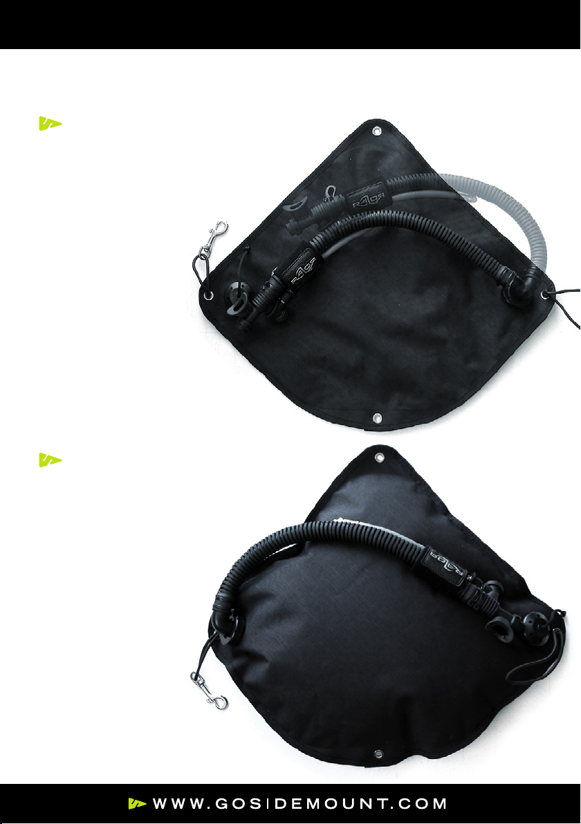
A Primary wing:
B 19” large diameter inflation
hose with fixed low profile
elbow and power inflator
C Large Razor Logo Wrap for
large diameter Inflation Hose
D 8” LPI Hose fit-
ted with Hose Hat
E Heavy Duty Pull Dump Valve
F Backup Wing:
G Oral Inflation Hose with
Bite-On Mouthpiece
H Low Profile Coin Dump Valve
I Separate Extension Piece
for fitting the top of the
BAT Wing to the DSP
of the Razor Harness
J Long Waist Bungee with
snap bolt attached
K Short Waist Bungee
no snap bolt
L Wing Tab with Bungee cord
M Wing Tri-glide (this will
already be fitted to your
Razor Harness if you
ordered a complete RSMS)
N 2 Button head screws
2 Washers
1 Hex nut
1.1 Package Content
BE
AD
F
J
K
N
I
N
L
G
H
C
M

4
Once your Razor Harness and T Weight System have been set up then you
can attach the BAT Wing to the Harness.
The BAT Wing should be worn with the Primary Wing on the outside and the
Backup Wing on the inside.
This makes finding both the Primary and Backup wing dump valves easier
and allows both to be vented more effectively and the Backup wing is very
well protected.
The design of the BAT wing places the position of
the dump valve and the inflator elbow in a well
protected low profile position between the Side
Mount tanks and the diver’s body.
In addition the outside material of the wing is not
placed between a hard object such as the dump
valve and the ceiling of a cave, or a sharp object
in a wreck for example where it may be more
prone to damage.
In the very unlikely event that the dump
valve or inflator elbow or large diameter
inflation hose should be damaged these
components are easily and cheaply
replaced which is not the case if the
wing material is damaged.
The BAT Wing is supplied with a 19”
long large diameter inflation hose
and an 8” long LPI hose fitted with
a hose hat.
This configuration should fit just
about everyone but shorter large
diameter inflation hoses of 16”
or 13” and shorter LPI hoses of
6” or 4” can be purchased
separately in order to custo-
mize hose lengths if required.
1.2 Overview
1 The Razor BAT Wing

5
The Hose Hats can be removed from the LPI hoses simply by just pulling
them off if required but are recommended for quick one hand operation of
the LPI/Schrader valve connection especially when diving in cold water with
thick gloves.
Hose hats can be purchased separately if you need to replace any or wish to
fit them to any existing LPI hoses.
The dump valve and the
large diameter inflator
hose elbow have compa-
tible fittings and can be
positioned on either the
left or right hand side of the
BAT wing according to
diver preference.
1.2 Overview
1 The Razor BAT Wing

6
Normally when using a Drysuit the dump
valve will be positioned on the left hand
side of the wing with the large diameter
Inflator hose on the right hand side
of the wing. The large diameter
inflation hose will deliver in
front of the diver across the
chest from the right hand
side with the LPI hose
delivering from the
regulator on the
right SM tank.
The BAT wing is supplied
already set up in this configuration.
When using a wetsuit normally the fittings
should be switched so that the large
diameter inflator hose is on the left
hand side and the LPI hose can
deliver from the regulator on the
left hand Side Mount tank.
1.2 Overview
1 The Razor BAT Wing

7
When changing the fittings make sure that they are not cross threaded
when screwing them in. The best way to do this is to turn anti clock-
wise until the threads drop into position and then tighten gently. No
force should be used to get the threads started.
1.2 Overview
1 The Razor BAT Wing
When the Inflator hose is unscrewed remember
to also take out the sealing O ring and replace
it in the other fitting with the rounded side
of the O ring facing down so that the flat
side of the inflator elbow will seal against
the flat side of the O ring.
The inflator elbow is keyed and it is im-
portant that it drops into position so that
it will seal on the O ring when the fitting is
screwed back into place.
8
The orientation of the elbow can be
adjusted so that the large diameter
inflation hose routes comfortably
under the arm and across
the chest.
To do this start the threads a couple of
turns but do not tighten them until the
correct orientation of the elbow is
achieved making sure the keyed
flange drops into place to
ensure a seal and then
tighten fully.
Once fitted pressure
test the seal by
inflating the wing
and making sure
it is airtight.
1.2 Overview
1 The Razor BAT Wing

9
When replacing the dump valve it is important that the spring is located in
the right position in the center and can move freely so that the valve does
not stick in the closed position.
Hold the dump cord and spring under
a little tension as you screw the fitting
back into place.
After tightening the dump valve
fully check to make sure that it
operates correctly and that the
spring moves freely when the cord
is pulled.
Check correct operation of
the wing by inflating and
deflating it and making sure
there are no leaks from either
of these fittings before going diving.
1.2 Overview
1 The Razor BAT Wing

10
You will need the following tools to rig your Razor BAT Wing:
2 Rigging the Razor BAT Wing
2.1 Tools
A hex wrench to fasten the button head screws.
(included with the complete system in the
Universal Spares Kit.)
A lighter to burn and seal the ends of the cut webing and elastic bungee cord.
A knife or scissors to cut the harness webbing and the elastic bungee cord.

11
The top of the BAT Wing bolts into the DSP of the
Razor Harness and should be positioned so that
the waist bungee cord and dump valve / infla-
tor elbow are at the height of your belly button just
above the waist strap of the Razor Harness.
Depending on the individual setup the top of the
wing can be bolted directly into the DSP or the
separate extension piece can be added
if required to get a perfect fit.
Ideally the top hole in the DSP should be
used to leave the bottom hole free to
attach the Lumbar Strap of the T Weight
System but you can attach both the
BAT Wing and the T Weight System
to the same hole either at the top or
bottom of the DSP using the longer
button head screw provided if
required.
Step 1: Adjusting and Attaching the top of the BAT Wing
to the DSP of the Razor Harness
2 Rigging the Razor BAT Wing

12
STYLES
1 A simple overhand knot
tied into the end of the
bungee cord will hold the
right hand side bungee in
place. This knot should be
on the inside of the wing.
B On the left hand side of
the wing a short waist bun-
gee cord is held in place
with 2 overhand knots tied
either side or the wing
grommet to secure it.
The BAT Wing Waist Bungee is designed to secure
the sides of the BAT Wing in a low profile stream-
lined position even when the wing is inflated and
still give easy unrestricted access to all of the Razor
Harness attachment points.
The waist bungee on the right hand side of
the BAT wing should have a long loop with
a small snap bolt attached to it. This will
feed across the waist and through the loop
of the crotch strap of the Razor
Harness and clip into the
short bungee loop attached
to the left hand side of
the BAT wing.
Step 2: Attaching and Adjusting the BAT Wing Waist Bungee
2 Rigging the Razor BAT Wing
A
B

13
The waist bungee should be fairly snug with the wing completely deflated and
both bungee cords will need to be adjusted to achieve the correct length and
tension to keep the BAT wing in a nice low profile position when it is inflated
and to prevent it from floating away from the divers body.
It will take a little bit of trial and error to get the length/tension correct so
leave the bungee cords long to begin with and do not tie the knots too tight
so that they can be released and moved easily if necessary.
Once the correct length is achieved then any excess bungee can be cut off
and the ends of the cords burnt to seal them and the knots snugged tight.
Step 2: Attaching and Adjusting the BAT Wing Waist Bungee
2 Rigging the Razor BAT Wing

14
The BAT Wing Rear Bungee is designed to secure the bottom of the
BAT Wing in a low profile streamlined position even when the wing
is inflated and still give easy unrestricted access to all of the Razor
Harness attachment points as well as the coin dump valve of the
Backup wing.
The Rear Bungee is secured to the BAT Wing with the Wing
Tab and the BAT Wing can be quickly and easily removed
from the Razor Harness by undoing the button head
screw leaving just the Wing Tab and bungee cord still
attached to the MBP.
The bungee cord is attached to the Wing
Tab with a Lark’s Head Hitch (aka Lanyard
Hitch). The bight of the Larks Head should
be on the outside of the wing tab.
Step 3: Attaching and Adjusting the BAT Wing Rear Bungee
to the Razor Harness
2 Rigging the Razor BAT Wing

15
The Wing Tab can also be removed from the bungee cord if required by pass-
ing the hitch of the Lark’s Head Hitch back over the body of the Wing Tab
which will just leave the bungee cord attached to the MBP.
Step 3: Attaching and Adjusting the BAT Wing Rear Bungee
to the Razor Harness
2 Rigging the Razor BAT Wing
The bottom of the BAT Wing with the Wing Tab
attached should line up with the slot of the Wing
Tri-glide of the Razor Harness that holds the Butt
B ring in position. The Wing Tri-glide can be
moved up or down the crotch strap webbing of
the Razor Harness to achieve the desired location.
This ensures that the Butt B ring will not be cov-
ered by the BAT Wing and will remain accessible
at all times even with the wing fully inflated.

16
The free ends of the bungee cord coming
from Lark’s Head Hitch on the Wing Tab
should be passed through the slot of the
Wing Tri-glide attached to the Razor Harness
and then run up to the MBP and passed
through the two holes either side of slot B.
The bungee cord can be locked in place with
a simple overhand knot tied on the inside of
the MBP.
The bungee cord should have some tension
on it with the BAT Wing completely deflated
so that it will be held in a streamlined low
profile position when inflated and will pull
tight when deflated.
It will take a little bit of trial and error to get
the length/tension correct so leave the bungee
cords long to begin with and do not tie the
knots too tight so that they can be released
and moved easily if necessary. Once the cor-
rect length is achieved then any excess bun-
gee can be cut off and the ends of the cords
burnt to seal them and the knots snugged
tight.
Step 3: Attaching and Adjusting the BAT Wing Rear Bungee
to the Razor Harness
2 Rigging the Razor BAT Wing

17
Step 4: Adjusting and Attaching the Large Diameter
Inflation Hose of the Primary wing to the Razor Harness
2 Rigging the Razor BAT Wing
With the BAT Wing now attached to the Razor Harness the harness should
be put on so that the large diameter inflation hose and power inflator can be
correctly positioned. The large diameter inflation hose with the power inflator
can be configured to use from either the right or left hand side.
This can be changed easily to a left hand delivery
orientation if required by removing the 2 cable ties
locking the power inflator in place and then rotat-
ing it 180 degrees before fastening with 2 new
cable ties to resecure it in place.
The BAT Wing is supplied with the large diameter
inflation hose and power inflator delivering from
the right hand side but it can be easily changed to
deliver from the left hand side if required as previ-
ously noted.
The “clocking” of the power inflator is also sup-
plied with a right hand delivery orientation with
the oral inflation mouthpiece facing up towards the
diver with the power inflator button and Schrader
valve on the underside.

18
Step 4: Adjusting and Attaching the Large Diameter
Inflation Hose of the Primary wing to the Razor Harness
2 Rigging the Razor Harness:
The oral inflator mouthpiece should now face up towards the diver with the
power inflator button and Schrader valve on the underside.
The large diameter inflation hose will run over the kidney area under the arm
and across the lower chest. The end of the Power inflator will be attached to
the D ring on the opposite shoulder with a loop of bungee cord tied with a
Fisherman’s knot through the loop of a small swiveling snap bolt.
The bungee loop can be positioned between the large diameter inflation hose
and LPI hose while diving so that it is securely retained.
The LPI hose to the power inflator should route directly across the chest from
the 5th port in the end of the swiveling turret of the regulator first stage.
It will run under the large diameter inflation hose.

19
Step 4: Adjusting and Attaching the Large Diameter
Inflation Hose of the Primary wing to the Razor Harness
2 Rigging the Razor BAT Wing
The large diameter inflation hose can be
secured to the lower shoulder strap of the
Razor Harness below the shoulder D ring
using the large Logo Wrap pro-
vided with the BAT Wing.
Please note that the BAT Wing Logo
Wrap which has to go around the large
diameter inflator hose as well as the web-
bing of the Razor Harness is larger than
the 2 Logo Wraps that come with the
Razor Harness. They should not be con-
fused as they are not interchangeable.
The orientation of the keyed hose elbow
can be adjusted as noted earlier to ensure
a streamlined comfortable routing of the
large diameter inflator hose. This is done
by loosening the locking ring a few turns
until it is possible to lift out the locking
plate of the elbow then rotating it until it
locks back into the desired orientation and
tightening the locking ring ensuring that it
has bottomed out properly and is forming a
good seal.

20
The oral inflator of the Backup wing should be routed over the right shoulder
and can be held securely in place by passing it under the neoprene logo
wraps on the right hand shoulder of the Razor Harness webbing.
The hose should bend towards the center of the chest just above the right
shoulder D ring and should be long enough to reach the mouth comfortably.
It can be held in place in a clean streamlined fashion by passing it through a
couple of bicycle tire inner tubes placed around the large diameter inflation
hose spaced a few inches apart.
The oral inflation hose should be positioned either on top or on the inside of
the large diameter inflation hose so as not to interfere with the LPI hose to
the power inflator that is routed underneath it.
Any excess hose can be cut off to customize the length. Remove the bite
on mouthpiece, cut the hose to the desired length and then replace the
mouthpiece.
Step 5: Positioning the Oral Inflator Hose of the Backup Wing
2 Rigging the Razor BAT Wing
Table of contents
Other Razor Diving Instrument manuals


