Razor eLEG User manual

www.Razorinternational.com Page 1 of 8
eLEG Owners Manual
Specifications
eLEG www.Razorinternational.com Page 2 of 8
Supply Voltage
9 to 30 Volt DC
Lift Capacity
25 Tonnes (60,000lb)
Leg Speed
34cm/min (13.5”/min) on high gear
eLEG Kit Weight
135~145Kg (dependant of foot Configuration)
Environmental
Fully weather & waterproof
Temperature
-30oC to 60oC (-22oF to 140 oF) (reduced performace at extremes)
eLEG Installation Instructions
PARTS LIST FOR eLEG
POWER KIT, consisting of:
•Battery (12volt)
•Battery Harness with 30 amp fuse (not shown)
•Battery Bracket
•Charge Harness(not shown)
•Battery Strap
•2 x M8 Clamp bolts, Spring washers and plates
•Charger (12 volt @ 2 amps)
•4 x M8 Bolt, Spring, Flat Washers & Nuts
•Battery Cover
•Rubber Pad(not shown)
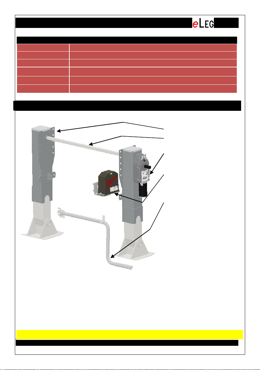
POWER KIT - ALTERNATIVE
•Extension Harness
•Offside Leg
•Square hollow
connecting shaft
•Drive Leg complete with
electric drive (gearbox
and motor) and controller
•Power Kit (as per below)
Note: This kit must be
used to supply the drive
leg power
•eLEG manual handle
with mounting hardware
CAUTION: DO NOT WELD TO TRAILER WITHOUT DISCONNNECTION NEGATIVE.

Installation Instructions
eLEG www.Razorinternational.com Page 3 of 8
•Read the entire instructions through prior to starting the installation to
ensure you have all the tools and equipment necessary to carry out the work.
•Unpack the eLEG parts and power kit and check components.
eLEG Installation Instructions
1. Mount the landing legs as per normal landing leg fitment, ensuring to cut the
square hollow shaft to the correct length and fitted between the legs so that
the offside leg is driven from the drive leg. The correct length must ensure
that no lateral pressure is applied to the drive shafts of the geared and slave
leg in the fully installed position(no bolts required)
2. Locate a solid point on the trailer chassis to mount the power kit, taking due
note of the size required for the battery (approximately 24cm wide, 21cm
high and 13cm deep (9 1/2'' x 8 1/4 '' x 5''). It must also be mounted in close
proximity to the drive leg as it will need to be connected to via the harness
supplied. The battery should be mounted in the orientation shown.
3. Using the supplied Template supplied to
mark hole locations is the trailer chassis.
(21cm x 6.5cm hole centres, 8.25'' x 2.5'')
Drill 4 off 9mm (3/8'') diameter holes.
4. Bolt the battery bracket to the trailer chassis with the bolts supplied,
ensuring to fit the spring washers.
5. The charge harness now needs to be connected to a power source on the
trailer. (9 to 30 Volts DC). There are three wires available to be connected to
keep the eLEG battery charged. The negative or common is and must
be connected to the trailer negative, there is a blue and brown wire available
that can be connected to a power source on the trailer. Typically the brown
can be connected to the running or clearance lights the blue wire could be
connected to either an auxiliary or even the stop lights on the trailer. You only
need one but two is an advantage. Refer to the wiring schematic shown.
Ensure the electrical connections to the trailer harness are robust and sealed.
Note: Make sure a proper earth is established between battery negative and
the trailer electrical circuit. (Experience has shown that electrical problems
caused by bad earth or low trailer voltage is responsible for most problems
associated with the installation of the eLEG. This affects the ability to keep
the battery charged. A test of the charge circuit is to connect the blue (or
brown) charge wire to the battery positive; a solid yellow LED light indicates
charger is operating as it should)

Installation Instructions
eLEG www.Razorinternational.com Page 4 of 8
6. Then connect the drive unit to the battery harness via the harness supplied.
Secure and protect the wiring as appropriate to minimise damage
7. Finally, locate a solid point
on the trailer chassis to
mount the eLEG manual handle
with hardware. Drill two
off 9mm (3/8'') diameter holes
using the bracket as a template
and bolt the handle bracket to
the trailer chassis.
Then lock manual handle with L bolt and clip into the hanger clip.
-ve
+ve
Brown Wire Trailer +ve (clearance
light)
Blue Wire Trailer +ve (auxillary)
White Wire Trailer –ve (earth)
Charger
Leg
Drive
12V Battery
Electrical Schematic
30 amp fuse
hanger
clip
L bolt
handle
bracket
eLEG
manual
handle
Operating Instructions
eLEG www.Razorinternational.com Page 5 of 8
eLEG Operating Instructions
Installed correctly your eLEG will give you years of trouble free service.
The electric drive and its associated battery are sealed maintenance free
items.
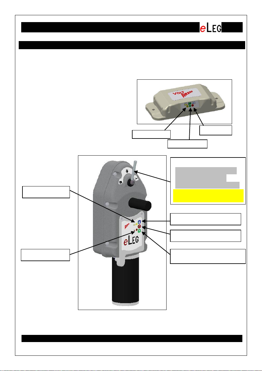
Your eLEG comes with a battery
charger. It is located inside the
battery cover. It will charge your
battery to the correct voltage if
connected to the trailer electrics as
described above. This is vital for the
longevity of the battery and to
ensure the eLEG landing legs
function correctly
Raise Button - Blue
Stop Button - Red
Lower Button - Green
Gear Change Lever
Elephant –Heavy lift
Central –Neutral
Cheetah–Fast Speed
Red LED
Yellow LED
Red LED
Yellow LED
Green LED
CAUTION: STOP MOTOR
BEFORE CHANGE GEAR

Operating Instructions
eLEG www.Razorinternational.com Page 6 of 8
CHARGER
The battery charger has three LED lights. For indication of the condition of the
battery and of power supply from the trailer their functions is as per the table
below:
CONTROLLER
To operate the legs you must first initiate (or wake up) the controller. This is
required to prevent the inadvertent or accidental operation of the legs which
could lead to hazardous and even dangerous situations.
You should also select the gear position you require. The high speed gear,
which is indicated by a , is generally used to get the legs to the ground fast
and also return them to their home position (fully up) once they have cleared
the ground. The high load gear, which is indicated by n,is generally used to
lift a loaded trailer once the legs are on the ground. The neutral position,
indicated by , is only used if there is a problem and it allows you to still
manually wind the leg. (refer below)
To initiate the controller press and hold the Stop button for 2 seconds. The
Red LED and Yellow LED will flash twice to acknowledge the controller has
been activated. It is noted that if the gear selection is in neutral you cannot
initiated the unit and you will get four Red LED flashes to indicate this
condition. First change the gear selection away from the neutral position
You may now operate in the legs in either direction by pressing the down
(green) button or the up (blue) button.
The legs will continue to travel in the direction selected until the preset load
condition is met. If the legs are travelling down in high speed this will be when
the legs first hit the ground, if they are going up it will be when the legs reach
the end of their travel and are fully home. (Note: The Maximum run time is 2
minutes)
The gear selection lever is simple operated by rotating it by hand either to the
left or right. If the legs are operating and the gear selector is changed it will
stop the motor and the Red LED will illuminate while in the neutral position.
The drive can be restarted once either high load or high speed is selected.
The Controller has two LED lights for indication of the operation and the
battery condition their functions is as per the table below:
Red LED
This indicates that supply is connected
Yellow LED
This indicates that the battery is charging.
Green LED
This indicates that the battery is fully charged

Operating Instructions
eLEG www.Razorinternational.com Page 7 of 8
Manual Operation.
In the event that there is a problem and the drive will not operate. You can still
operate the legs manually.
To do this first remove the plastic protective sleeve from the drive shaft that
protrudes out from the gearbox (shown below). Put the gear selector in the
neutral position. This will disengage the motor from the legs. Attach the
eLEG manual handle supplied to the shaft( locked with 10mm L bolt) and wind
as per a normal manual set of landing legs.(Refer page 4 for detailed parts
breakdown).
Red LED
One Flash
A button activation is acknowledged by one flash.
Note: this is only once the controller is initiated as
elsewhere described.
One flash also indicates that the pre-set maximum
increase in load has been exceeded and the
motor has been stopped.
It will flash once again if the button is pressed for the
same direction indicating this is an inhibited operation.
Two Flashes
Indicates that the pre-set maximum load has been
reached and the motor has been stopped
It will flash twice again if the button is pressed for the
same direction indicating this is an inhibited operation.
Three Flashes
This indicates a locked mechanical condition such
as gear failure or motor failure
(Check motor and gearbox)
Four Flashes
An over temperature condition has been reached.
Allow time to cool down before operating again.
Continuous
Indicates that the gear lever is in the neutral
position and you cannot operate the eLEG in that
condition. You must change the lever to a gear
setting before you can operate the eLEG.
Note: this will only occur once the controller is initiated.
Yellow LED
Five Flashes
This indicates that the battery is low and requires
to be charged.
Note: this will only flash once the controller is initiated.
Red LED &
Yellow LED
Two Flashes
Both LED’s will flash twice upon controller
initiation. Refer operation instructions

Service and Maintenance
eLEG www.Razorinternational.com Page 8 of 8
eLEG Service
The eLEG power drive gearbox is designed to be maintenance free. There is
no serviceable parts. The gearbox is a sealed pre-lubricated unit, as is the
battery, the charger and controller.
Should any of the components have an issue, the drive system has been
designed to be modular so that each component can be readily replaced in
minutes. These components are the battery and its associated charger, the
electric motor and the electronic controller. Please refer to the illustration
below for change out of each component.
To remove electric motor first
remove the two M8 bolts and the
motor can then be pulled out
from the gear box(Note: The
longer M8 screw is bolted to the
left hole of the controller).
Electric
Motor
Motor retaining bolts &
spring washers
(6mm Hex Key
required,Max Torque
20N.m/14.75ft.lb)
Note: Long M8 bolt must
go in the left side
To remove the controller,
first disconnect the
harness and remove the
motor then remove the two
M4 screws and the
controller can be lifted out.
Controller
Controller
retaining screws
(T20 Torx key
required, Max
Torque 2N,m/
/1.47ft.lb
CAUTION: DO NOT ATTEMPT TO REMOVE BEFORE
FIRST DISCONNECTING BATTERY POWER
Drive Shaft protective cover.
Remove to operated gearbox
manually with standard crank
handle
Refer page 2 for
detailed parts
breakdown
Table of contents


