Loctite EQ RC30 User manual

1
EQ RC30 Manual Reservoir
IDH 2814022
Operating Manual

2
Table of Contents
1Please Observe the Following...................................................................................................3
1.1 Emphasized Sections...........................................................................................................3
1.2 For Your Safety.....................................................................................................................3
1.3 Unpacking and Inspection ..................................................................................................3
1.4 Packing List...........................................................................................................................4
1.5 Features.................................................................................................................................4
1.6 Field of Application (Intended use) ...................................................................................4
2Description...................................................................................................................................5
2.1 Theory of Operation..................................................................................................................5
2.2 Operating Elements and Connections ..................................................................................5
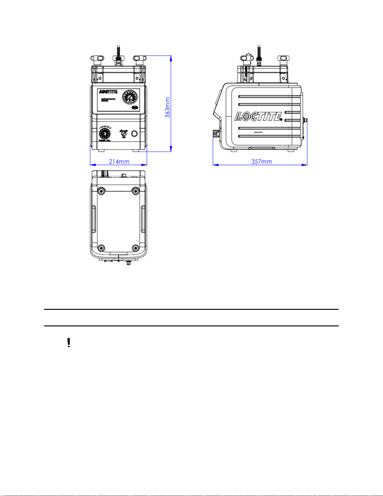
3Technical Data.............................................................................................................................6
4Installation....................................................................................................................................7
4.1 Environmental and Operating Conditions..............................................................................7
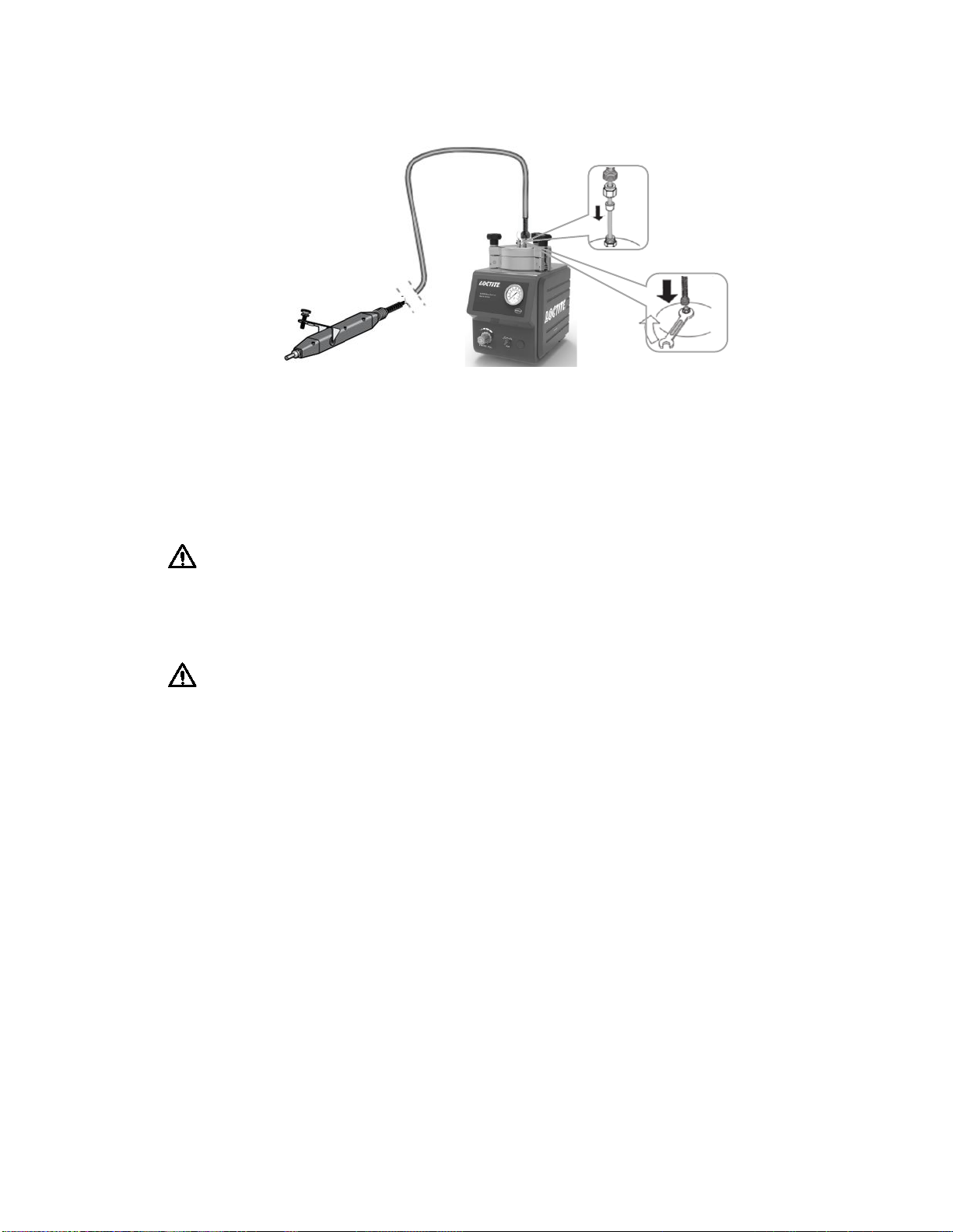
4.2 Connecting the Unit..................................................................................................................8
4.3 Filling and Refilling the Product Reservoir............................................................................9
5Operation....................................................................................................................................10
5.1 First Operation.........................................................................................................................10
5.2 Adjust the Level Sensor.........................................................................................................11
6 Application Hints.......................................................................................................................13
7Troubleshooting.........................................................................................................................13
8Care and Maintenance .............................................................................................................15
9Accessories and Spare Parts...................................................................................................16
10 Diagrams ....................................................................................................................................16
11 Warranty.....................................................................................................................................17
12 Declaration of Conformity........................................................................................................18

3
1 Please Observe the Following
1.1 Emphasized Sections
Warning!
Refers to safety regulations and requires safety measures that protect the operator
or other persons from injury or danger to life.
Caution!
Emphasizes what must be done or avoided so that the unit or other property is not
damaged.
Notice:
A notice gives recommendations for better handling of the unit during operation or
adjustment as well as for service activities.
1.2 For Your Safety
For safe and successful operation of the unit, read these instructions
completely. If the instructions are not observed, the manufacturer can assume no
responsibility.
Do not expose the connecting cable to heat, oil, or sharp edges.
Make sure the Unit stands stable and secure.
Use only original equipment replacement parts.
Always disconnect the power supply before servicing the unit.
Observe general safety regulations for the handling of chemicals such as
Loctite®adhesives and sealants. Observe the manufacturer’s instructions as stated
in the Safety Data Sheet.
While under warranty, the unit may be repaired only by an authorized Loctite
service representative.
1.3 Unpacking and Inspection
Carefully unpack the Loctite®EQ RC30 Manual Reservoir and examine the items
contained in the carton. Inspect the unit for any damage that might have occurred in

4
transit. If such damage has occurred, notify the carrier immediately. Claims for
damage must be made by the consignee to the carrier and should be reported to the
manufacturer.
1.4 Packing List
•EQ RC30 Manual Reservoir x 1
•Equipment Manual x 1
•Reservoir Tank Fitting: ¼ inch NPT x ¼ Inch Tubing x 1
•Bottle Holder x 1
•¼” NPT to 6 mm inlet supply line connector x 1
•Anti-Bubbler Fitting and Tubing Kit x 1
•Bottle spacer disc x 1
1.5 Features
•User-friendly design.
•Operational with manual dispense valve
•Includes Low level sensor for process control
•Equipped with a 0 to 7 bar (0-100psi) manual pressure regulator
•Easy to read pressure gauge
•Accommodates a variety of Loctite packages.
1.6 Field of Application (Intended use)
The Loctite EQ RC30 Manual Reservoir is suitable for the application of Loctite
adhesive with a manual applicator at manual workstations such as in workshops,
laboratories, and industrial installations.
It is possible to dispense anaerobic, UV curing adhesives and cyanoacrylate adhesives.
The reservoir can accommodate 250ml, 500gram, 1 liter and 2kg adhesive packages
which deliver adhesive to dispensing valves.
The capacity of the EQ RC30 Manual Reservoir is:
-500 gr. bottle for CA Products -1 lb. bottle
-250 ml bottle for Anaerobics -1 Liter bottle
-Bottle with a φ124mm and -2kg bottle
a height of 250mm

5
2 Description
2.1 Theory of Operation
The Loctite EQ RC30 Manual Reservoir is connected to an external pneumatic supply.
An uncovered bottle of Loctite® product is placed directly into the EQ RC30 Manual
Reservoir, the feedline is inserted into the product, and the reservoir lid is clamped in
place.
The manual reservoir is equipped with a 0 to 7 bar (0-100psi) pressure regulator that
regulates the dispensing pressure of the reservoir. Adhesive is fed from the reservoir
to a manual dispense valve. When the valve is actuated to open then adhesive flows
through the outlet dispense needle.
The amount of product dispensed is controlled by four main factors:
•Dispensing pressure set in the reservoir
•Length of time the dispensing valve remains open
•Valve stroke
•Dispensing needle size
2.2 Operating Elements and Connections
4
1
3
5
6
8
9
10
2
7

6
1. Reservoir Pressure Regulator
2. Air Pressure ON/OFF Switch
3. Reservoir Pressure Gauge
4. Valve Pressure Relief
5. Reservoir/Feedline Fitting
6. Reservoir Knob x 3
7. Reservoir Lid
8. Pneumatic Connection P in
9. Low Level Connector XS2
10. Low Level Sensor
3 Technical Data
Dimensions (L x H x W): 214x363x357 mm
Total weight: Kg (lbs.) 3.5 (8)
Pneumatic Supply: Clean, dry air not to exceed 116 psi (8bar). and
filtered with a maximum of 10 micron.
Pneumatic hose size: External dia. 6mm
Operating Temperature: +10 °C to +40 °C (+50 °F to +104 °F)
Storage Temperature: - 10 °C to +60 °C (+14 °F to +140 °F)

7
4 Installation
Before using the equipment for the first time check it carefully for signs of
external damage. If any shipping damage is found DO NOT USE THE EQUIPMENT –
return it to your supplier immediately.
4.1 Environmental and Operating Conditions
-Keep product feedline as short as possible. The shorter the feedline the smaller the
specific resistance and lower the dispensing pressure can be. Avoid kinking of the
feedline.

8
-Use flexible pneumatic hoses and Loctite supplied product feedlines to prevent
unnecessary loads on the fitting and to ensure compatibility.
-Keep all fittings tight.
-No direct sunlight; no UV light.
-No condensing humidity.
-Avoid direct contact with water.
4.2 Connecting the Unit
-Use only the cable and hose sets supplied.
-Connect the air pressure supply to reservoir P in (8).
-If connecting to an external controller, connect the tank cord to the 9 pin D-sub
connector XS2 (9) located on the rear panel of reservoir.
-Insert feedline through the reservoir lid to the dimension shown below. Alternatively
use the reference line shown on the housing to set the feedline length. Cut the end
of the feedline at an angle as shown below.
-Connect dispensing valve.

9
-If two dispense valves are used, remove blanking plug from the reservoir lid and
replace with additional reservoir/tube fitting.
4.3 Filling and Refilling the Product Reservoir
Warning!
Never fill the product directly into the reservoir!
The pneumatic and safety devices would become clogged and therefore ineffective!
Warning!
Before loosening the reservoir locking knobs (6), the EQ RC30 Manual Reservoir
must be depressurized (pressure-free)!
When dispensing cyanoacrylate and an empty signal is shown, refill the product
reservoir immediately, since air in the product line results in curing of the product!
The reservoir is depressurized when the depressurizing valve (2) is in “OFF” position
and reservoir pressure gauge (3) indicates no pressure.
•Loosen the reservoir knobs and remove the lid.
•Check that there is no condensed moisture at the bottle or the sensor surface.

10
•Place the bottle in the bottle holder (see the right figure).
•Check that the product bottle inserted in the bottle holder is
pressed again the level sensor.
•Insert the product feedline into the bottle and put on the lid.
•Uniformly tighten the reservoir knobs by hand.
•Set the depressurizing valve (2) to “ON” position (pressurize)
by hand.
•Continue dispensing with the selected dispensing pressure.
5 Operation
5.1 First Operation:
Warning!
Before loosening the reservoir locking knobs (6), the EQ RC30 Manual Reservoir
must be depressurized (pressure-free)!
The EQ RC30 Manual Reservoir is depressurized when the reservoir pressure gauge
indicates no pressure.
In any case:
•Set the depressurizing valve (2) to position (depressurize).
5.1.1 Inserting the Product Bottle
Follow procedure as described in section 4.3.
5.1.2 Priming the Feedline
•Check that the product reservoir and the dispensing valve are connected correctly
according to their instruction manuals.

11
Notice:
To avoid air bubbles during dispensing, the product line must be filled and then purged
of air.
•Position the dispensing valve as specified in its instruction manual to ensure
bubble-free filling of the product line.
•Set the pressure regulator (2) to a dispensing pressure of 0.5bar (approx. 7 psi)
and open the manual dispense valve until
the produce flows out.
•For viscous products, increase the pressure
slowly in steps until the product flows out.
Warning!
Hold the dispensing valve upright enables air
to be purged out of the valve.
5.1.3 Adjusting the Dispensed Quantity
If the dispensed flow is too slow or too fast:
•On the pressure regulator (1) increase or decrease the dispensing pressure.
•Open the dispensing valve to check the dispensed quantity.
•Repeat the last two steps until the desired dispensed quantity is achieved.
If the desired dispensed quantity is not achieved:
•Attach a larger (or smaller) dispensing needle, repeat the steps of Section 5.1.3.
5.2 Adjust the Level Sensor
Notice:
The level sensor is set in manufacturing and can be adjusted according to the type of
product used, the size of the bottle, and orientation of the basket with spacers if
required. If small bottles are used the supplied Bottle spacer disc can be placed in

12
the base of the reservoir to raise the height of the bottle to reduce the residual
adhesive in the bottle when low level is used.
Before adjusting the Level Sensor:
1. Remove the plastic cap from the backside of reservoir.
2. Connect the reservoir cord to the connector XS2 (9) on the
reservoir as well as to socket of the controller to be used.
3. Empty a bottle of the product you use.
4. Leave as much residue in the bottle as is required in order
to prevent air getting into the product feed line.
5. Insert the product bottle. For small bottles use the bottle holder. For 250ml product
bottle, pay attention to ensure the bottle is aligned with the level sensor.
6. Check that the product bottle inserted into the bottle holder is pressed against the
level sensor. Only then the correct adjustment of the level sensor is possible.
Procedure to Adjust the Level Sensor:
1. Turn controller power switch - “ON”.
2. Remove the metal screw from the level sensor.
3. With an electrician’s screwdriver, find the point at which
the sensor switches to the condition inactive. The LED is
OFF”.
4. Check this adjustment with a full bottle and an empty bottle again.
5. Refit the metal screw to the level sensor.
6. Put the plastic cap back.
Notice:
The correct adjustment is exactly the point when the sensor switches “OFF”.
Do not go beyond that point!

13
6 Application Hints
As with all adhesives, performance depends on conditions of use. Suggestions or
recommendations contained herein are for guidance only since actual conditions of
use are outside the supplier’s control.
6.1 Shutdown for Longer Periods of Non-use (>recommended idle time)
•Disconnect the pneumatic supply from the unit.
•Clean the product hose and dispensing valve.
Recommended maximum idle times for different products are shown below:
Adhesive
Maximum idle time for dispensing Systems
Anaerobic
2 weeks
Cyanoacrylate
1 week
UV-acrylate
2 weeks
Acrylate
1 week
Epoxy
2 weeks
Activator
n.a.
Primer
n.a.
6.2 Returning to Operation after Longer Periods of Non-use
•Reconnect the pneumatic supply to the unit.
•Check the installation according to Chapter 4.
•Return to operation according to Section 5.1.
7 Troubleshooting
Before proceeding with any repair or maintenance operation disconnect the EQ RC30
Manual Reservoir from the main air supply.

14
Malfunction
Possible Cause
Corrective
No needle movement on
the pressure gauge.
No air pressure present.
Check pneumatic supply.
Product reservoir not
switched on.
Check product reservoir.
Pressure gauge is defect.
Replace pressure gauge.
The desired pressure is not
achieved.
Supply pressure
inadequate.
Increase the supply pressure.
No Product, too little or too
much product.
Dispensing pressure not
set correctly.
Adjust dispensing pressure
setting.
Pressure hose not properly
connected.
Connect air pressure hose
correctly.
Dispensing needle is
clogged, too small or too
large.
Replace the dispensing
needle.
Dispensing valve not
correctly connected or
defect.
Check the dispensing valve
(see instruction manual for
dispensing valve).
Product reservoir not
switched on.
Check product reservoir.
Product reservoir is empty.
Refill product reservoir (see
Section 4.3).
Air bubble in the product
Product reservoir is empty.
Refill product reservoir (see
section 4.3).
Dispensing valve not
correctly connected or
defective.
Check the dispensing valve
(see instruction manual for
dispensing valve).
Product reservoir pressure
is too high.
Lower pressure, longer
dispensing time.
Pressurized air escapes
between reservoir housing
and reservoir lid.
Reservoir Knob is not
tightened.
Tighten the reservoir knob.
O-ring leaks.
Grease or renew the O-ring.
Pressurized air escapes at
the product connection 5.
Union nut on the product
connection 5 not tightened.
Carefully tighten the union nut.

15
8 Care, Cleaning and Maintenance
8.1 Care
-Occasionally the O-ring at the reservoir lid should be lubricated with silicone grease.
This will prolong the life of the O-ring.
Notice: Clean hands after application of grease to ensure surfaces to be
bonded are clean.
-Clean the sensor surface as required.
-Both the bottle surface and the sensor surface must be free of condensed moisture!
8.2 Cleaning
-Prior to extended idle times or when changing of the product type, clean the product
hose and the dispensing valve.
-Loosen reservoir locking knobs (6) and remove the reservoir lid (7).
-Clean product residue from the outside of the feedline hose.
-Remove the product bottle and insert a container with approx. 0.5 liter of cleaning
agent.
-Put on the reservoir lid (7) and uniformly tighten the reservoir locking knobs (6).
-Operate the dispenser continuously until dry air streams out of the dispensing valve
(see operating instructions for the dispensing valve).
-Remove the empty cleaning agent container.
8.3 Maintenance
-Check the reservoir knobs and the product feed line on a regular basis. If there is
any sign of cracks, replace them!
-Clean, dry, filtered air must be used. If it is not, the solenoids on the controller will
be fouled over time.
Notice: If the required air quality is not achieved, install a Loctite® filter
regulator. In the US order a 5 m filter using Part Number 478603. In Europe or Asia,
order a 10 m filter using Part Number 88649.

16
9Accessories and Spare Parts
Item
Description
IDH#
Spare Parts
1
Reservoir/tube Tank Fitting, ¼ inch NPT x ¼ inch Tubing
360636
3
¼ inch O.D. Black PE Teflon Lined feedline Tubing (10mtr/33ft length)
142646
4
Tank Lid O-ring for Reservoir
478505
5
Pressure Safety Relief Valve
360462
6
Anti-Bubbler Kit, 2 Adapters & 2 Sleeves
478569
7
Silicone Grease, 6 Gram Tube
88722
Accessories
1
Loctite Air Filter, Regulator, Gauge (Mechanical version) - US
478603
Loctite Air Filter, Regulator, Gauge (Mechanical version) –EU/Asia
88649
10 Diagrams
EQ RC30 Manual Reservoir Pin Connection:

17
11 Warranty
Henkel expressly warrants that all products referred to in this Instruction Manual for Loctite®
EQ RC30 Manual Reservoir (hereafter called “Products”) shall be free from defects in
materials and workmanship. Liability for Henkel shall be limited, as its option, to replacing
those Products which are shown to be defective in either materials or workmanship or to
credit the purchaser the amount of the purchase price thereof (plus freight and insurance
charges paid therefor by the user). The purchaser’s sole and exclusive remedy for breach of
warranty shall be such replacement or credit.
A claim of defect in materials or workmanship in any Products shall be allowed only when it
is submitted in writing within one month after discovery of the defect or after the time the
defect should reasonably have been discovered and in any event, within (12) months after
the delivery of the Products to the purchaser. This warranty does not apply to perishable
items, such as fuses, filters, lights, etc.. No such claim shall be allowed in respect of products
which have been neglected or improperly stored, transported, handled, installed, connected,
operated, used or maintained. In the event of unauthorized modification of the Products
including, where products, parts or attachments for use in connection with the Products are
available from Henkel, the use of products, parts or attachments which are not manufactured
by Henkel, no claim shall be allowed.
No Products shall be returned to Henkel for any reason without prior written approval from
Henkel. Products shall be returned freight prepaid, in accordance with instructions from
Henkel.
NO WARRANTY IS EXTENDED TO ANY EQUIPMENT WHICH HAS BEEN ALTERED,
MISUSED, NEGLECTED, OR DAMAGED BY ACCIDENT.
EXCEPT FOR THE EXPRESS WARRANTY CONTAINED IN THIS SECTION, HENKEL MAKES
NO WARRANTY OF ANY KIND WHATSOEVER, EXPRESS OR IMPLIED, WITH RESPECT TO
THE PRODUCTS.
ALL WARRANTIES OF MERCHANTABILITY, FITNESS FOR A PARTICULAR PURPOSE, AND
OTHER WARRANTIES OF WHATEVER KIND (INCLUDING AGAINST PATENT OR
TRADEMARK INFRINGEMENT) ARE HEREBY DISCLAIMED BY HENKEL AND WAIVED BY
THE PURCHASER.

18
THIS SECTION SETS FORTH EXCLUSIVELY ALL OF LIABILITY FOR HENKEL TO THE
PURCHASER IN CONTRACT, IN TORT OR OTHERWISE IN THE EVENT OF DEFECTIVE
PRODUCTS.
WITHOUT LIMITATION OF THE FOREGOING, TO THE FULLEST EXTENT POSSIBLE UNDER
APPLICABLE LAWS, HENKEL EXPRESSLY DISCLAIMS ANY LIABILITY WHATSOEVER FOR
ANY DAMAGES INCURRED DIRECTLY OR INDIRECTLY IN CONNECTION WITH THE SALE
OR USE OF, OR OTHERWISE IN CONNECTION WITH, THE PRODUCTS, INCLUDING,
WITHOUT LIMITATION, LOSS OF PROFITS AND SPECIAL, INDIRECT OR CONSEQUENTIAL
DAMAGES, WHETHER CAUSED BY NEGLIGENCE FROM HENKEL OR OTHERWISE.
12 Declaration of Conformity
TO BE CONFIRMED

19
Henkel Corporation
One Henkel Way
Rocky Hill, CT 06067-3910
USA
Henkel Canada Corporation
2515 Meadowpine Boulevard
Mississauga, Ontario L5N 6C3
Canada
Henkel Corporation
Automotive/ Metals H.Q.
32100 Stephenson Hwy,
Madison Heights 48071
USA
Henkel Capital, S.A. de C.V.
Calzada de la Viga s/n Fracc.
Los Laureles
Loc. Tulpetlac, C.P. 55090
Ecatepac de Morelos, MEXICO
Henkel Singapore Pte Ltd
401, Commonwealth Drive
#03-01/02 Haw Par Technocentre
SINGAPORE 149598
Henkel (China) Company Ltd.
No. 928 Zhang Heng Road,
Zhangjiang, Hi-Tech Park, Pudong,
Shanghai, China 201203
Henkel Loctite Korea
8F, Mapo Tower, 418,
Mapo-dong, Mapo-gu,
Seoul, 121-734, KOREA
Henkel Japan Ltd.
27-7 Shin Isogo-cho, Isogo-ku
Yokohama, 235-0017
JAPAN
Henkel AG & Co. KGaA
Henkelstraße 67,
40191 Düsseldorf
Deutchland
www.equipment.loctite.com
® and ™ designate trademarks of Henkel Corporation or its affiliates. ® = registered in the U.S. and elsewhere.
© Henkel Corporation. All rights reserved. Data in this operation manual is subject to change without notice.
Manual P/N: n/a, Rev A, Date: 10/18/2021
Table of contents
Other Loctite Industrial Equipment manuals

Loctite
Loctite Zeta 7411-S User manual

Loctite
Loctite Zeta 7411-S User manual

Loctite
Loctite ZETA 7401 User manual

Loctite
Loctite UVALOC 400 User manual

Loctite
Loctite CL15 UV User manual

Loctite
Loctite Zeta 7215 User manual

Loctite
Loctite EQ CL32 LED Spot 365nm User manual

Loctite
Loctite Hysol 98038 User manual
Popular Industrial Equipment manuals by other brands

Reich Kupplungen
Reich Kupplungen R-Flex HBSX-8-RH Series Assembly instructions

Siemens
Siemens SITRANS WFS300 operating instructions

Siemens
Siemens ULTRAMAT 23 Series Equipment manual

Proluxe
Proluxe Doughpro DP2300PRE Operation manual

TLV
TLV PowerDyne P46S instruction manual

ABB
ABB HT610642 Operation manual