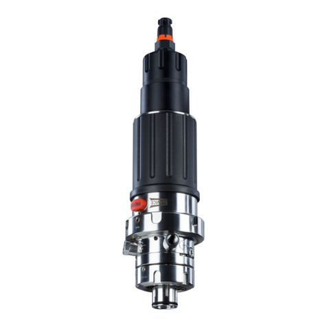
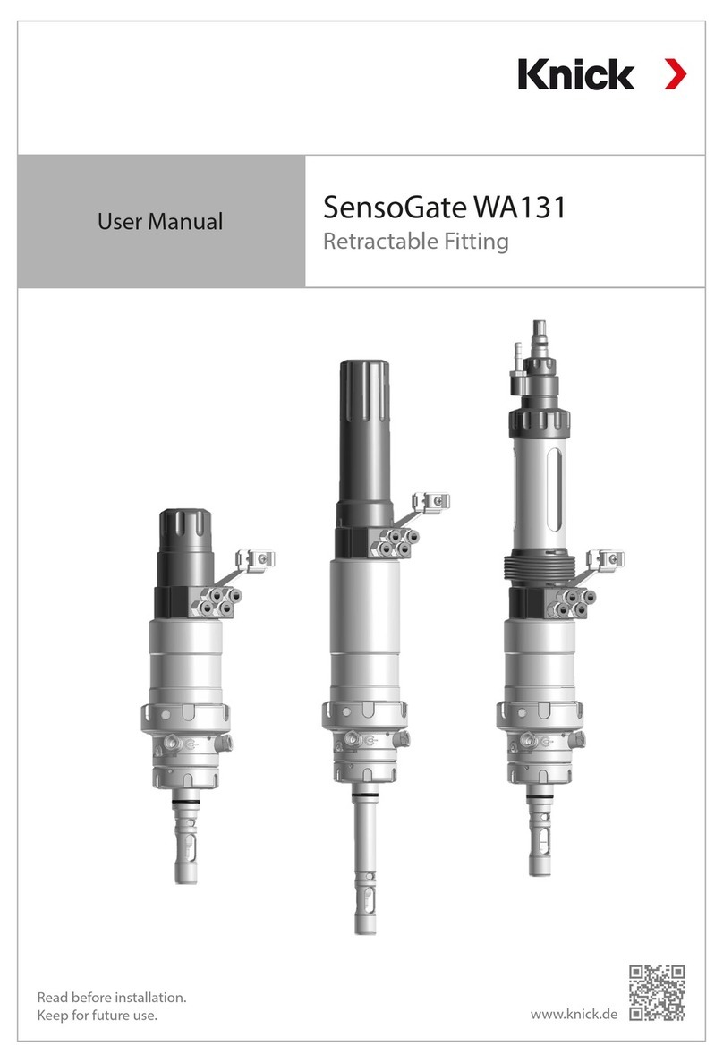
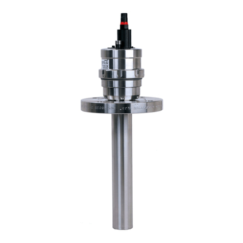
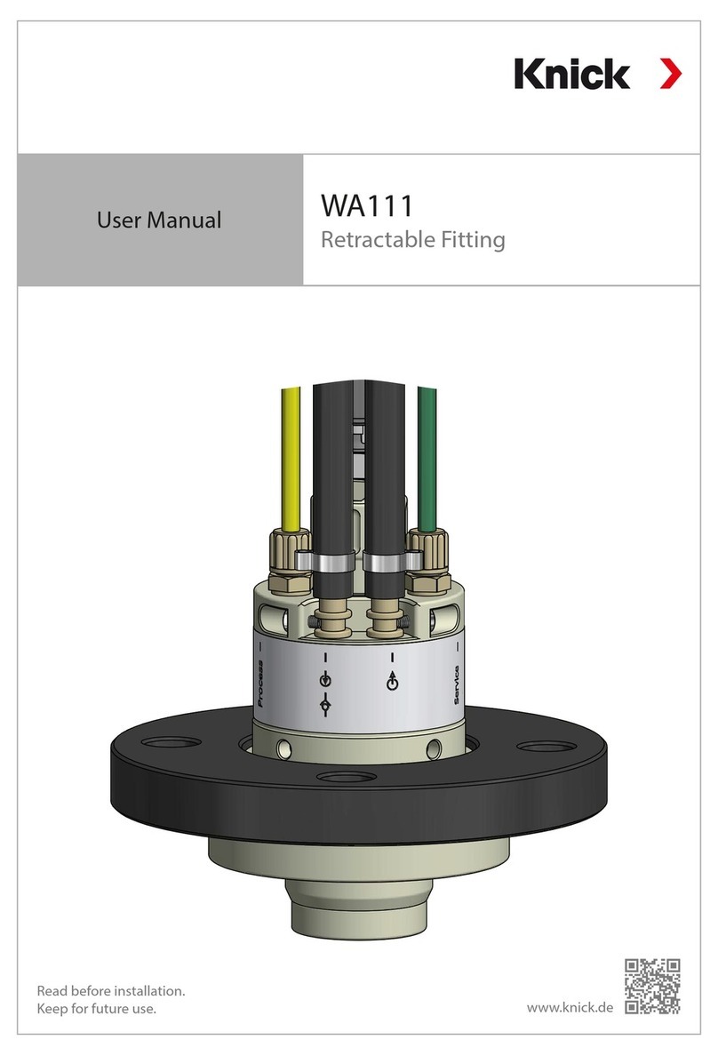
Knick Ceramat WA 153 User manual

User Manual
English
Latest Product Information: www.knick.de
Ceramat WA 153
Sensor Lock-Gate

Warranty
Defects occurring within 1 year from delivery date shall be remedied free of charge at our plant
(carriage and insurance paid by sender).
©2014 Subject to change without notice
Exclusions from warranty
Wear parts (gaskets) and damage caused by improper use are excluded from warranty.
Return of products
Please contact our Service Team before returning a defective device. Ship the cleaned device to the address
you have been given. If the device has been in contact with process fluids, it must be decontaminated/
disinfected before shipment. In that case, please attach a corresponding Declaration of Contamination
(seepage39), for the health and safety of our service personnel.
Trademarks
The following trademarks are used in this manual without further marking:
Ceramat®, Protos®, Unical®, Uniclean®
are registered trademarks of Knick Elektronische Messgeräte GmbH & Co. KG, Germany

3
Safety Information
Please note:
Supplementary information is provided in the Ceramat Maintenance Instructions (Maintenance / Spare Parts /
Accessories)
NOTICE
Process-related risks
Knick Elektronische Messgeräte GmbH & Co. KG assumes no liability for damages caused by process-related
risks known to the operator, which would in fact not permit the use of the sensor lock-gate.
!
WARNING
Always make sure that the sensor lock-gate cannot be activated by other persons during servicing or
installation (eg, cleaning or replacing the sensor).
During operation the drive unit of the sensor lock-gate is rotating rather quickly by 140°.
There is a risk of injury!
Be sure to observe:
Work on the sensor lock-gate must only be performed by personnel authorized by the operating company
and specially trained for handling and operating the sensor lock-gate.
!
WARNING
Use in accordance with EC-Type-Examination Certificate
The Ceramat WA 1**-X... sensor lock-gate,
EC-Type-Examination Certificate KEMA 04ATEX4035, with the marking II 1 GD c II,
is a Category 1 device intended for use in Zone 0 or Zone 20.
The following shall be observed in accordance with EN 13463-1:
The Ceramat WA 1**-X... sensor lock-gate shall not be used as Category 1 equipment if process-wetted parts
of the process adaptation contain, by mass
- more than 10 % in total of aluminum, magnesium, titanium and zirconium, or,
- more than 7.5 % in total of magnesium, titanium and zirconium.
The Ceramat WA 1**-X... sensor lock-gate shall not be used as Category 2 equipment if process-wetted parts
of the process adaptation contain, by mass
- more than 7.5 % in total of magnesium.
When the Ceramat WA 1**-X... sensor lock-gate is used as Category 3 equipment, there are no special
requirements for the material.
If it can be proved for the application that there is no risk of ignition from incendive friction, impact or
abrasion sparks, then the limitations given above shall not apply.
Please note:
For permanent use in a liquid process medium, it can be assumed that there is no risk of ignition.
Please note:
From the product code, you can see which materials are used in your product.
The product code is printed on the rating plate and included in this user manual.

4Table of Contents
Safety Information .........................................................................................................................3
Table of Contents............................................................................................................................4
Intended Use...................................................................................................................................5
Rating Plates................................................................................................................................................................ 6
Package Contents...........................................................................................................................7
Product Coding...............................................................................................................................8
Function Description....................................................................................................................10
Composition of the Sensor Lock-Gate........................................................................................11
Information on Installation .........................................................................................................13
Connection to Unical or Uniclean ...............................................................................................17
Installing/Removing a Sensor .....................................................................................................18
pH Sensors.................................................................................................................................................................19
Sensor Dismount Guard........................................................................................................................................19
Installing/Removing a Solid-Electrolyte Sensor........................................................................20
pH Sensors, Oxygen Sensors, Conductivity Sensors..................................................................................20
Installing/Removing a Liquid-Electrolyte Sensor......................................................................21
pH Sensors.................................................................................................................................................................21
Cavity Rinsing Function ...............................................................................................................23
Maintenance Work on the Drive Unit .........................................................................................24
Removing the Drive Unit .............................................................................................................25
Installing the Drive Unit...............................................................................................................26
Installation Dimensions...............................................................................................................27
Solid Electrolyte.......................................................................................................................................................27
Liquid Electrolyte.....................................................................................................................................................28
Process Adaptations and Immersion Depths (Examples).........................................................................29
Specifications................................................................................................................................30
Maintenance Intervals .................................................................................................................31
Lubricants, O-Rings ......................................................................................................................32
Sealing Kits for Maintenance and Servicing ..............................................................................33
Accessories / Spare Parts .............................................................................................................34
Declaration of Contamination.....................................................................................................39
Index..............................................................................................................................................40

5
The Ceramat pneumatic sensor lock-gate with ceramic sealing is used for installing a sensor for measuring
process variables in liquid media. The sensor can be cleaned, calibrated, or replaced under process conditions
(pressure and temperature).
Since the pneumatic drive unit and the process unit with the ceramic sensor lock-gate are separate modules,
the drive unit can be removed and replaced under process conditions.
The sensor lock-gate is suitable for sensors with an outer diameter of 12 mm, for sensors:
• with solid electrolyte, length 225 mm, sensor head with PG 13.5
• with liquid electrolyte, length 250 mm
• for optical sensors with a body diameter of 12 mm or 12.7 mm (1/2“)
(For installing an optical sensor, you require a special adapter which is listed in the Product Coding under
“Special version”. Information on design and use of the suitable adapter is provided in a supplementary
datasheet.)
The Ceramat sensor lock-gate allows:
• inserting and retracting the sensor under process pressure (sensor lock-gate)
• calibrating or adjusting the measuring system and cleaning the sensor in the running process
(different options available)
• removing or replacing the sensor after separation from the process (in SERVICE position)
The Ceramat sensor lock-gate has been developed and manufactured in compliance with the applicable
European directives and standards.
Compliance with the European directives and standards is confirmed by the EC Declaration of Conformity.
Compliance with the European Harmonized Standards for use in hazardous locations is confirmed by the
EC-Type-Examination Certificate.
To ensure smooth performance of the measuring points with the Ceramat, a number of important operating
and maintenance parameters must be complied with (see Ceramat Maintenance Instructions).
There is no particular direct hazard caused by the operation of the device in the specified environment.
Intended Use
!
CAUTION
Safe use
• If you are not sure whether the sensor lock-gate can be safely used for your intended application, please
contact the manufacturer.
• Take account of the influences of humidity, ambient temperature, chemicals and corrosion.
• To ensure safe use of the equipment, you must follow the instructions given in this manual and observe
the specified temperature and pressure ranges.
!
WARNING
Application in hazardous locations
For hazardous-area applications, the sensors used must ensure proper separation of the ATEX zones. When
the sensor lock-gate is in SERVICE position, the sensor may be replaced within a Zone 1 hazardous location.

6Intended Use
Rating Plates
Ceramat WA 15x-N
Drive
Process
Ceramat WA 15x-X
Drive
Process
Process, small rating plates

7
Package Contents
Check the shipment for transport damage and completeness.
The package should contain:
• Sensor lock-gate
• Documentation
• Test certificates

8Product Coding
WA 153-
Explosion protection For hazardous area Zone 1
Without
Sensor Sensor, Ø 12 mm with PG 13.5
pH sensor Ø12 mm with pressurization, pres-
sure chamber for compressed air supply
Optical sensor, Ø 1/2” (12.7 mm)
Optical sensor, Ø 12 mm
Material of gaskets FKM
EPDM
EPDM - FDA
FKM - FDA
FFKM - FDA
FFKM
Material of
sensor protection sleeve
Hastelloy C22
PEEK
1.4404
Titanium
Material of sensor socket Hastelloy C 22, without protection
Hastelloy C 22, short protection
1.4404, without protection
1.4404, short protection
1.4404, long protection
1.4404, full protection
PEEK, without protection
Titanium, without protection
Titanium, short protection
Scraper for sensor socket Without
PEEK, natural
Immersion depth Special immersion depth 23-104 mm (1 mm increments)
Immersion depth 105 mm (max.)
Process-wetted material Hastelloy C22
1.4404
Titanium
Process adaptation Flange, loose, 1.4571, PN10/16, DN 50
Flange, loose, 1.4571, PN10/16, DN 65
Flange, loose, 1.4571, PN10/16, DN 80
Flange, loose, 1.4571, PN10/16, DN 100
Flange, loose, 1.4571, PN10/16, DN 125
Flange, loose, 1.4571, PN10/16, DN 150
Flange, loose, 1.4571, PN10/16, DN 200
Flange, loose, 1.4571, PN40, DN 50
Flange, loose, 1.4571, PN40, DN 65
Flange, loose, 1.4571, PN40, DN 80
Flange, loose, 1.4571, PN40, DN 100
Flange, loose, 1.4571, PN40, DN 125

9
WA 153-
Flange, loose, 1.4571, PN40, DN 150
Flange, loose, 1.4571, PN40, DN 200
Dairy pipe DN 50
Dairy pipe DN 65
Dairy pipe DN 80
Dairy pipe DN 100
Flange, loose, ANSI 316,150 lbs, 2”
Flange, loose, ANSI 316, 150 lbs, 2 1/2”
Flange, loose, ANSI 316, 150 lbs, 3”
Flange, loose, ANSI 316, 150 lbs, 3.5”
Flange, loose, ANSI 316, 150 lbs, 4”
Flange, loose, ANSI 316, 150 lbs, 5”
Flange, loose, ANSI 316, 150 lbs, 6”
Flange, loose, ANSI 316, 300 lbs, 2”
Flange, loose, ANSI 316, 300 lbs, 2 1/2”
Flange, loose, ANSI 316, 300 lbs, 3”
Flange, loose, ANSI 316, 300 lbs, 3.5”
Flange, loose, ANSI 316, 300 lbs, 4”
Flange, loose, ANSI 316, 300 lbs, 5”
Flange, loose, ANSI 316, 300 lbs, 6”
G2 1/4 for ARF210/215 K 8
Clamp 2.5" J 3
Clamp DN 50, DIN 32676 J H
BioControl, 1.4404, DN 65 L 2
Varivent 1.4404 (from DN 50) V 1
Probe guard Without
With, version 1
Special version Without
Equipped with special grease (provided by customer)
Sensor protection tube for optical sensor (Hellma) with Ø12 mm
and additional anti-twist protection for the sensor cables,
rotating adapter 1/2”/PG13.5 (according to drawing)
Customer-specific special datasheet
Sensor protection tube for opt. sensor with Ø12 mm or 1/2” (12.7 mm)
and additional anti-twist protection for the sensor cables,
rotating adapter Ø12 mm (1/2”)/PG13.5 (according to drawing) J
Ceramat, inlet and outlet made of 1.4404 K
Entries shown in italics are special options, delivery time on request
Product Coding
10 Function Description
Mounting
• Possible mounting angle: 15° above horizontal.
• Mounting angle 360° (i.e. even upside down) for
special sensors only containing thickened electrolytes
which thus cannot flow.
The pneumatically operated sensor lock-gate allows calibrating or adjusting the measuring system and clean-
ing the sensor in the running process. For that purpose, the sensor can be moved between two positions:
PROCESS position: The sensor is located in the process medium.
SERVICE position: The sensor is located in the calibration chamber.
In SERVICE position the measuring system can be calibrated or adjusted or the sensor can be cleaned.
Using compressed air, a control unit such as the Unical 9000 moves the sensor between SERVICE position
and PROCESS position and leads different calibration and/or cleaning liquids to the sensor located in the
calibration chamber.
These liquids leave the calibration chamber through an outlet hose, i.e. they are displaced from the
calibration chamber by following liquids or by compressed air.
To replace the sensor, you must move the sensor lock-gate into SERVICE position.
With the Unical 9000 probe controller, all media, control air, and the check-back cable for position indication
of the probe are connected to the sensor lock-gate through a compact connector (multiplug).
Since the pneumatic drive unit and the process unit with the ceramic sensor lock-gate are separate modules,
the drive unit can be removed and replaced under process conditions.
15°
15°

11
The Ceramat sensor lock-gate consists of 2 main units: drive unit and process unit.
The drive unit performs the movements required to open and close the ceramic rotary slide
and to move the sensor into and out of the process.
The process unit comprises the ceramic sensor lock-gate with calibration chamber in the probe hous-
ing as well as the process adaptation (e.g., flange or dairy-pipe screw joint). Drive unit and process unit
can be separated by the operator even under process pressure when certain safety precautions are taken
(see“Maintenance Work on the Drive Unit” on page24).
Composition of the Sensor Lock-Gate
Process adaptation
(eg, flange)
Drive unit
Process unit
Fixing bracket
Probe housing
with ceramic
rotary slides
Media connection
to Unical 9000(X)
probecontroller
(not included with
sensor lock-gate)
Sensor
connecting cable
Multiplug
Outlet for
rinsing/calibration media
(outlet hose not
included with
sensor lock-gate)
Coupling nut

12 Composition of the Sensor Lock-Gate
Drive units
Process adaptations (examples)
Flange Dairy-pipe screw joint Varivent
Drive unit for sensors with
solid electrolyte
Drive unit for sensors with
liquid electrolyte

13
Information on Installation
For operation of the Ceramat, you must connect control air, rinsing or calibration media, and the
electricalcheck-back signal for indicating the probe position.
There are two basic options for this.
When the Ceramat is operated with a Unical or Uniclean electro-pneumatic controller and the Protos measur-
ing system, the cables and tubings for air pressure, rinsing/calibration media and check-back are combined in
a single hose with just one plug connection (multiplug). This hose is referred to as media connection.
This media connection is installed on the Ceramat together with the outlet hose.
When you do not use a probe controller (Unical or Uniclean and Protos measuring system), you can connect
the supply lines for control air, rinsing/calibration media and electrical check-back to the Ceramat with a free
hose connection via the ZU 0631 standard-media interface.
Connection for operation with
Unical/Uniclean und Protos
Connection for operation with
ZU 0631 standard media interface

14 Information on Installation
15°
15°
Installing the outlet hose
Do not install the outlet hose more than 1 meter below calibration chamber level (see figure 2).
Doing so raises the danger of air being sucked out of the calibration chamber due to the drop in pressure.
Leakage of the calibration chamber due to gravity alone is prevented by the loop in the outlet hose when the
Ceramat is installed at an angle of up to 15° above the horizontal (see figure 1).
With horizontal to upside-down installations, you must install an appropriate hose bend above the level of
the calibration chamber to prevent leakage from the calibration chamber (see figure 2).
max.
1 meter
Calibration chamber
level
Above level of calibration chamber
Calibration chamber
Outlet hose
Hose bend
Inlet
Sensor
Fig. 1
Fig. 2

15
Connecting the outlet hose
Turn the outflow nipple so that the outlet hose
points outwards (see figure on the left). Before
tightening the coupling nut, correctly align and
insert the outflow nipple!
Outlet hose
Coupling nut
Coding recesses
Coding bars
Outflow nipple
Information on Installation
Installing the sensor cable
(pH, oxygen, and conductivity cables)
Attach the connecting cable (A) to the sensor and
connect to the fixing bracket (B) in a loop as shown in
the illustration.
Using clamp (C), attach the cable lightly so that the
cable is secured and not constricted. The rotational
movement of the Ceramat would otherwise damage
the cable.
A
B
C
F
NOTICE
Check positioning of coding recesses and coding
bars to lock the connection.
NOTICE
The cable loop must be long enough so that the
cable does not impede the stroke movement of
the fitting.
Connect equipotential bonding cable to terminal
(F) (if required).

16 Information on Installation
The following procedure is recommended for
installing the media connection (also applies to
installation of ZU 0631 standard-media interface):
Attaching the hose to the fixing bracket of the
Ceramat
Attach the bracket of the media connection to
the fixing bracket of the Ceramat with mounting
screws.
Mounting screws
Connecting the multiplug
Connect multiplug (A)
with 2 screws (B) as shown.
A
B

17
Connection to Unical or Uniclean
The media connection is available in 5 m, 10 m, 14 m, or 17 m length (other lengths on request).
It consists of a Ø 30 mm corrugated hose with a metal coil.
You can also order special lengths (also heated or with wall ducts).
2 variants are available:
• for rinsing only (without branch outlet to media adapter)
• for calibration and cleaning function (with branch outlet to media adapter)
Connections
The connections for media adapter and sensor lock-gate are of a plug-in design. They are mechanically fixed
by screwing. Each fluid is fed to the sensor lock-gate through a separate tube of the media connection.
Check valves in the multiplug minimize contamination and prevent mixing of the calibration fluids.
Connection to Unical or Uniclean
The corrugated hose is screwed to the joining piece of the Unical or Uniclean.
You can easily feed the different media tubes through the slit in the securing nut. The different tube lengths
and diameters provide for a clear assignment to the different connection points (color coded).
See also Unical 9000(X) / Uniclean 900(X) installation manual.
Connection to media adapter
This connection is plugged and screwed to the media adapter. It includes the media tubing.
Electrical connection is made via a plug-in connector.
See also Unical 9000(X) / Uniclean 900(X) installation manual.
Connection to Unical 9000(X)
or Uniclean 900(X)
Connection to media adapter
(omitted for“rinsing only” variant)
Multiplug for connecting the Ceramat

18 Installing/Removing a Sensor
NOTICE
Sensors must only be installed or removed by trained personnel authorized by the operating company.
The Ceramat sensor lock-gate must be in SERVICE position.
This position is attained by:
• the “Maintenance”menu when controlled by Protos 3400(X)
(see user manual of PHU 3400(X)-110 module)
• the service switch (see Unical 9000(X) installation manual)

19
Sensor Dismount Guard
(only for sensors with solid electrolyte)
In conjunction with the Unical or Uniclean electro-pneumatic
controllers and the Protos measuring system, the Ceramat is
fitted with a sensor dismount guard. This serves to prevent the
immersion of the sensor lock-gate without sensor (a message
is triggered in the Protos). If the sensor is absent or incorrectly
mounted, compressed air noticeably and audibly escapes from
below the drive's coupling nut.
The outflowing compressed air is detected by a flow switch
in the Unical and signals the missing or incorrectly mounted
sensor to the Protos.
The sensor dismount guard only works with a correctly
installed O-ring (B) and slip ring (A) on the sensor. If these
elements are not present, the “Sensor dismounted” message is
shown in the Protos display.
Before installing a new sensor, check whether there are any
sealing elements at the bottom of the sensor holder from
previous installations which have not been removed!
A
B
Installing/Removing a Sensor
Note
When using a PEEK scraper ring on the sensor socket of the Ceramat, or when retrofitting a Ceramat with
sensor socket including scraper ring as accessory ZU 0705, ZU 0706, or ZU 0707 (see Accessories page 35),
the proper functioning of the sensor dismount guard in combination with the Unical/Uniclean cannot be
guaranteed. Buildup of contaminations can result in high stripping forces which impair the functioning of the
sensor dismount guard.
NOTICE
Therefore, the operator of the Ceramat must always make sure that a sensor is installed before moving the
probe to PROCESS position (measuring).
pH Sensors
Be sure to follow the assembly instructions step by step.
Preparations:
• Check whether the sensor is damaged (glass broken?).
Never install a damaged sensor.
• Check whether slide washer or O-ring on the sensor are damaged and replace if required.
• Remove watering cap from the sensor tip and rinse sensor with water.

20 Installing/Removing a Solid-Electrolyte Sensor
Installing the sensor
1) Move probe into SERVICE position.
The sensor must only be installed in SERVICE position.
2) Use appropriate sensors (C) only:
Diameter: 12-0.5 mm Length: 225 mm
Observe pressure resistance of the sensor.
3) Before installing the sensor, check that there is no liquid
flowing out of the outlet (ceramic slides or probe hous-
ing might be defective).
4) Check whether slide ring (A) or O-ring (B) on the sensor
are damaged.
5) Screw in the sensor head (19 mm A/F, PG 13.5 thread)
with a max. torque of 3 Nm (recommended tool: 19mm
wrench, eg, Knick ZU0647).
6) Install sensor cable and media connection (see
“Information on Installation“ on page13).
ZU 0647
A
B
C
Removing the sensor:
1) Move probe into SERVICE position. The sensor must only
be removed in SERVICE position.
2) Before removing the sensor, check that there is no liquid
flowing out of the outlet (ceramic slides or probe hous-
ing might be defective).
3) Loosen the sensor plug.
4) Loosen the sensor using a suitable tool and pull it out.
Be sure not to cant the sensor because it might break
(recommended tool for removing the sensor:
19 mm A/F, eg, Knick ZU0647 wrench).
Tool for sensor installation
pH Sensors, Oxygen Sensors, Conductivity Sensors
Other manuals for Ceramat WA 153
1
Table of contents
Other Knick Industrial Equipment manuals

Knick
Knick ARD 250 User manual

Knick
Knick SensoGate WA131MH User manual

Knick
Knick ARD50EL User manual

Knick
Knick SensoGate WA131 User manual

Knick
Knick ProLine P16800 User manual

Knick
Knick SensoGate WA 132 Series User manual

Knick
Knick Ceramat WA 154 User manual

Knick
Knick Ceramat WA160 User manual

Knick
Knick WA111 User manual