Loepfe YARNMASTER 3N1 Install guide

YARNMASTER ®3N1
46261003en
Fitting Instruction
Schlafhorst ACO 240


Loepfe Brothers Ltd.
Kastellstrasse 10
P. O. Box 582
8623 Wetzikon/Switzerland
Phone +41 43 488 11 11
Fax +41 43 488 11 00
E-Mail service@loepfe.com
Internet www.loepfe.com
YarnMaster®is a registered trademark of Loepfe Brothers Ltd.
for Switzerland and other countries.
All further company and product names are trading names or
registered trademarks of the relative companies.
The content of this Operating Instruction is protected by cop-
yright. All rights reserved. No part of this may be reproduced
in whatever form (by printing, photocopying, microfilm or oth-
er) without a written grant of Loepfe Brothers Ltd., nor may it
be processed or distributed by any electronic mean.
Copyright©2012 Loepfe Brothers Ltd., Switzerland
03. 2012 / Version 1.0.0

43N1
INHALTSVERZEICHNIS

TABLE OF CONTENTS
Table of Contents
Safety Instructions 7
Norms and Regulations 7
Instruction Manual 7
Liability 7
Operational Notes 8
Fitting 3N1 9
Preparation of Major Cabling 10
SCU Side 10
Power Supply Connection 11
LAN to Q-Board 12
Connection 4K to SCU 13
Fitting of Sensors 14
Cabling of the Section Electronic (SE) 16
Connections to SAG 17
Power Supply for SE 18
Q-Board Connections 20
Earthing of SE-Board 21
SE Address 22
Labeling of SE-Board 22
Sensor Cables 23
Specifications 25

3N1

73N1
SAFETY INSTRUCTIONS
Norms and Regulations
The LOEPFE YarnMaster®3N1 yarn clearing system is a prod-
uct which has been inspected for technical safety. It complies
with the following directives:
98 / 37 / EEC Machinery Directive
2006 / 95 / EC Low Voltage Directive
2004 / 108 / EC Electromagnetic Compatibility
Instruction Manual
To prevent faults and operating errors, we recommend to
carefully read this Instruction Manual and to carefully follow
the instructions given.
!Indicates warnings which, if not properly observed,
could harm your health, impair the functioning of
the equipment or the security of your data.
Note: The screen representations in this manual serve as illus-
tration only. They should not be used as setting examples!
A copy of this Instruction Manual must be kept easily acces-
sible near the machine.
Liability
The manufacturer assumes no liability for damage caused by:
Noncompliance with the safety, operating and mainte-
nance instructions contained in this Manual.
The use of spare parts / non-OEM parts / conversion parts
not supplied by us.
Unauthorized conversion and modification of the yarn
clearer.
Normal wear.
Safety Instructions

83N1
SAFETY INSTRUCTIONS
Operational Notes
The installation of the equipment should only be performed
by qualified personnel being familiar with all safety checks,
installation and service guidelines.
Improper operation of the equipment could cause hazards.
In accordance with 98 / 37 / EEC, 2006 / 95 / EC, 2004 / 108 /
EC. Do not open any covers (cooling, fire protection, contami-
nation, spark interference etc.)
Electronic components and assemblies (printed circuit
boards) are endangered by electrostatic charges! Be-
ware of touching the soldered connectors, pin contacts be-
fore they have been discharged statically. Hold the units at
the periphery only.
Upgrade works must be carried out with switched off
mains switch only. Failing to observe this warning may
lead to death or severe injuries!
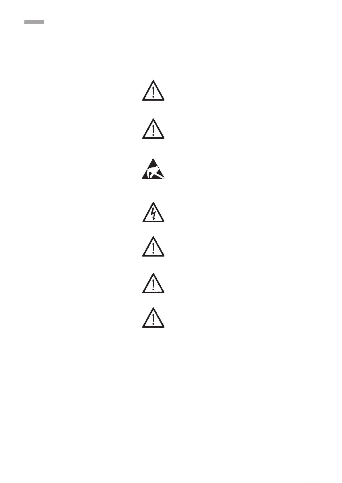
This yarn clearer system must be connected to the power
supply only after installation of all front panels, plug-in boards
and provided covers, in particular of the central unit.
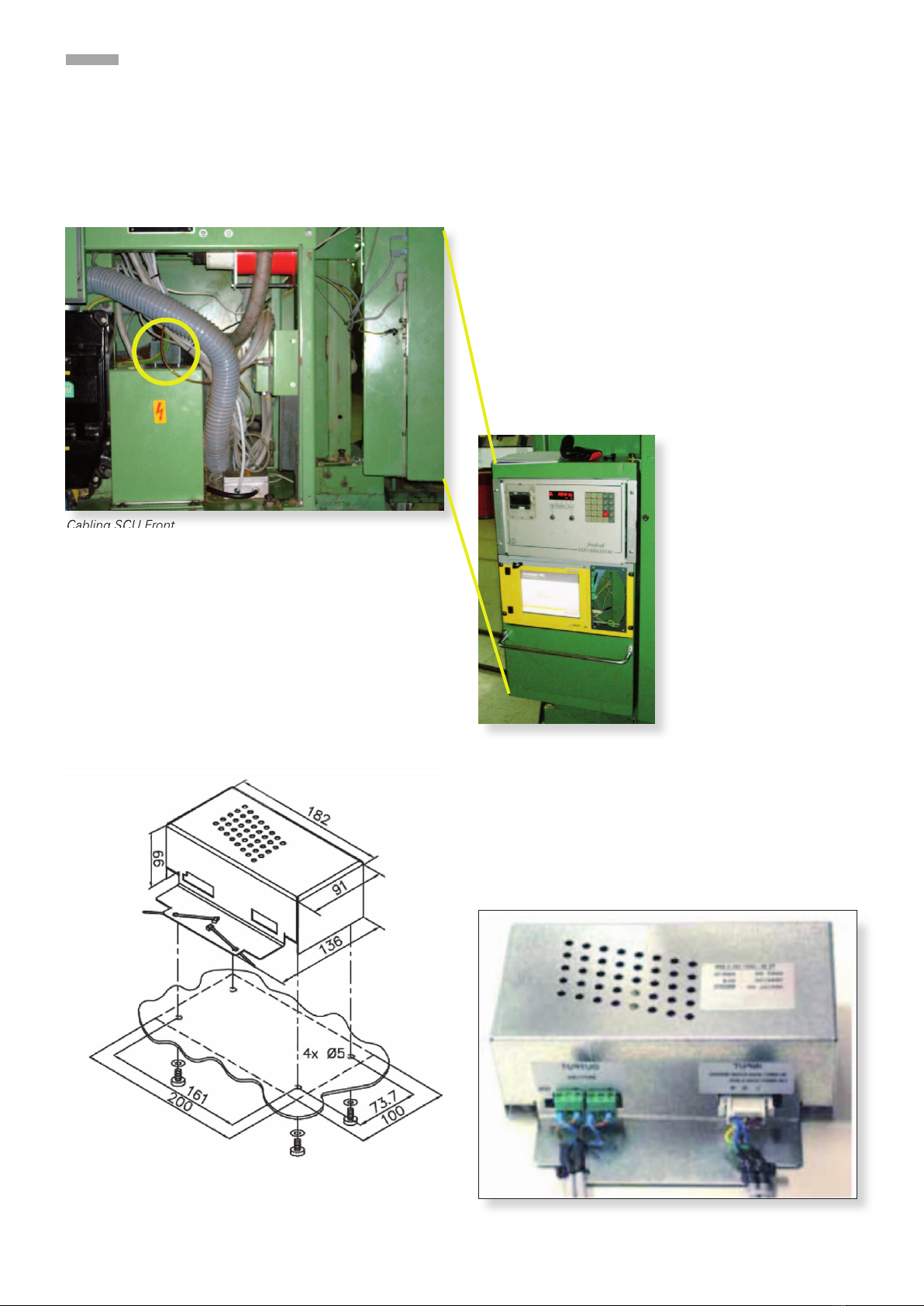
Connect the supply input of the Q-UNIT 3N1 to a 24Vdc SELV
supply, that is switched off if the machine is switched off, or
if the emergency button is pushed.
Make the earth connections.
Unit specifications see last page.

93N1
FITTING 3N1
Fitting 3N1
Basic situation is a machine without any clearer system.
If there is one fitted to the machine, it must be removed before installing 3N1
Time instructions (based on 240 Rotors)
Time for Approx. man hours
Deinstallation of old system 14
Installation of 3N1 (full and basic) 36
Time for: Hours
Start up 5
Time for: (only one time) Hours
Teaching 8
Work on Informator:
Usually this should be done by the ACO responsible person in the mill.
Print or save report with all data.
!Note: Start up and checks in the Diagnosis

10 3N1
PREPARATION OF CABLING
SCU Side
Power supply 24 V
Ground
4K
LAN to Q-Board
The power supply must be installed by an electrician
Cabling SCU Front
1. Drill 4 holes Ø 5mm and deburr.
2. Install the power supply as shown. Mounting parts and
cable ties are provided
3. Fix the power input and power output cables with the ca-
ble ties to the power supply, as shown.
4. Make sure that the cables are tied at the cable mantle and
not at the wires.
Power Supply connections
Power Supply mounting
4x spring washer M4 DIN6798
4x screw M4x10 DIN7985
Preparation of Major Cabling
Cabling SCU Front

113N1
PREPARATION OF CABLING
Black: Power supply from machine or external
White: Power supply for SCU: 24V (30W), only use one
of the outputs!!
Power: To be connected with an external power supply or
have it connected to the machine electronics by an electri-
cian. Power from Schlafhorst’s control unit.
Power Supply Connection

12 3N1
PREPARATION OF CABLING
LAN to Q-Board
Yellow: LAN to Q- Board
Red: 4K cable to 4K card at Schlafhorst Informator
Blue: Ground: to housing (or somewhere else with an as-
sured ground)
White: power cable for power supply, front side as installed.
Black: power supply from machine or external.
Remove the cover:
Use the cable track to fit the cable before you feed it into the
cable channel (above). This cable goes directly to the first SE
Board (long LAN cable)
Connect the 4K cable to the interface in
the Informator.

133N1
PREPARATION OF CABLING
Connection 4K to SCU
Red: 4K
4K cable to 4K card (inside of the Informator)
The card is written down.

14 3N1
FITTING OF SENSORS
Prepare the sensors and screw the mounting piece to the
sensor.
Screw the sensing head into the existing hole of the bar (Pic-
ture 1) and position it in the middle of the hole of the mount-
ing piece (Picture 2). It is necessary to do it in this way to be
able to make a readjustment.
Picture 2Picture 1
Fitting of Sensors

153N1
FITTING OF SENSORS
At least: the measuring slit should be in the range of the press
roller. (Picture)
If this is not so, the metal bar with with screwed on sensor
should be slided. This should be done by the mill mechanics.
To do this the adjusting parts for the sensor should be used,
if available.
Adjustment

16 3N1
CABLING OF THE SECTION ELECTRONIC (SE)
Cabling of the Section Electronic (SE)
1Main powerline (from machine or external line) Specification see power supply unit
Black: 1/ 2 Power supply 24V for SE
Yellow: LAN to SE-boards (splitter on each section)
Red: Start / Stop cable IF to connect the SAG)
For exact cabling see the following description. Before starting with the cabling the sensors should be fitted!
View from below
machine head first section
freefree
Informator
SAG unit calculator LOEPFE power supply
1
2

173N1
CABLING OF THE SECTION ELECTRONIC (SE)
Connections to SAG
Red: Q-Stop cable, each for one side (12 rotors)
The SAG board requires an Interface print. It can be simply
plugged on.
Position 1 to connector lower connector on the SE-Board
Position 2 to connector superior connector on the SE-Board
(top connector)

18 3N1
CABLING OF THE SECTION ELECTRONIC (SE)
Power Supply for SE
The power supply must be installed separately. The conduc-
tor is looped in in series. The main conductor can be pow-
ered by Schlafhorst or externally. A first cable is laid from this
power supply up to the first empty shaft door. There it is con-
nected to the serial line, which must be laid into the shafts.
The transformer must be screwed onto the empty shaft cover
(see drawing page 10).
Black; Power supply to SE
White: Main power line from machine or external.


20 3N1
CABLING OF THE SECTION ELECTRONIC (SE)
Q-Board Connections
Red: Stop cable:
Lower for SAG Board IF connector number 1
Superior for SAG Board IF connector number 2
White: Power supply 24 V from SAG
Yellow: LAN to SCU, is splitted by each section see the following picture
Other manuals for YARNMASTER 3N1
3
This manual suits for next models
4
Table of contents
Other Loepfe Industrial Equipment manuals

Loepfe
Loepfe YARNMASTER 1N1 User manual

Loepfe
Loepfe YARNMASTER 3N1 Install guide

Loepfe
Loepfe YARNMASTER 3N1 Install guide

Loepfe
Loepfe YARNMASTER ZENIT+ User manual

Loepfe
Loepfe YarnMaster PRISMA User manual

Loepfe
Loepfe YarnMaster Zenit User manual

Loepfe
Loepfe YARNMASTER 1N1 User manual

Loepfe
Loepfe YARNMASTER 3N1 Install guide