manuals.online logo
Brands
  1. Home
  2. •
  3. Brands
  4. •
  5. RC WARBIRDS
  6. •
  7. Toy
  8. •
  9. RC WARBIRDS MiG-29 Retract Kit User manual

RC WARBIRDS MiG-29 Retract Kit User manual

Popular Toy manuals by other brands

FUTABA GY470 instruction manual

FUTABA

FUTABA GY470 instruction manual

LEGO 41116 manual

LEGO

LEGO 41116 manual

Fisher-Price ColorMe Flowerz Bouquet Maker P9692 instruction sheet

Fisher-Price

Fisher-Price ColorMe Flowerz Bouquet Maker P9692 instruction sheet

Little Tikes LITTLE HANDIWORKER 0920 Assembly instructions

Little Tikes

Little Tikes LITTLE HANDIWORKER 0920 Assembly instructions

Eduard EF-2000 Two-seater exterior Assembly instructions

Eduard

Eduard EF-2000 Two-seater exterior Assembly instructions

USA Trains EXTENDED VISION CABOOSE instructions

USA Trains

USA Trains EXTENDED VISION CABOOSE instructions

Modellbau Laffont Z1601 Assembly instructions

Modellbau Laffont

Modellbau Laffont Z1601 Assembly instructions

NOCH 12905 instruction manual

NOCH

NOCH 12905 instruction manual

Eduard Ki-61-Id quick start guide

Eduard

Eduard Ki-61-Id quick start guide

Viessmann Vollmer 45616 Mounting instruction

Viessmann

Viessmann Vollmer 45616 Mounting instruction

Vollmer 42004 Mounting instruction

Vollmer

Vollmer 42004 Mounting instruction

Phoenix Model CLASSIC-EP instruction manual

Phoenix Model

Phoenix Model CLASSIC-EP instruction manual

H-KING Sopwith Camel British WW1 Fighter instruction manual

H-KING

H-KING Sopwith Camel British WW1 Fighter instruction manual

MODSTER Predator 4x4 Crawler user manual

MODSTER

MODSTER Predator 4x4 Crawler user manual

DHK Hobby 8136 User instruction manual

DHK Hobby

DHK Hobby 8136 User instruction manual

THUNDER TIGER Raptor 50 V2 kit manual

THUNDER TIGER

THUNDER TIGER Raptor 50 V2 kit manual

Timberkits Skateboarder instructions

Timberkits

Timberkits Skateboarder instructions

Hangar 9 Funtana 125 Assembly manual

Hangar 9

Hangar 9 Funtana 125 Assembly manual

manuals.online logo
manuals.online logoBrands
  • About & Mission
  • Contact us
  • Privacy Policy
  • Terms and Conditions

Copyright 2025 Manuals.Online. All Rights Reserved.

JOINTLY DEVELOPED WITH
WWW.RC-WARBIRDS.COM Page 1/16
MiG-29 Retract Kit
(for the HET-RC Mini Air Retract System)
The MiG-29 Retract Kit was designed to allow the easy installation of
the HET-RC mini Air Retract system into the twin EDF MiG-29.
We recommend to install the retract kit before starting to build any
other part of the plane as this will greatly ease the installation.
Before you start building the MiG-29 please go through the
instructions on the following pages and study the pictures and
building guidelines carefully. Please also study the main MiG-29
construction manual as it will give you further hints which will ease
the building process.
You will find that the plane is very easy and quick to build.
JOINTLY DEVELOPED WITH
WWW.RC-WARBIRDS.COM Page 2/16
Items required to complete the retract kit installation:
•30 min epoxy
•Milled fiberglass
•Drill (e.g. Dremel tool) with 1, 1.5 and 2mm drill
•X-acto Knife
•Sandpaper (220-180)
•1x HET-RC 9gram Servo (switched retract valve)
•1x Feather servo with at least 1.8kg torque (example: Hitec HS-65HB)
(nose gear steering)
A rotary tool such as a Dremel will greatly help in the building process.
A drum sander and cutting disk is highly recommended to cut the necessary
retract openings into the fiberglass fuselage.
Please note:
Due to the higher take-off weight of the MiG-29 with installed retracts we highly
recommend a setup with at least 2x Typhoon 2W-20 Motors, suitable ESC and
LiPo battery. We further recommend the use of a concrete runway to reduce
stress on the landing gear.
JOINTLY DEVELOPED WITH
WWW.RC-WARBIRDS.COM Page 3/16
The retract kit includes the following items:
1x Nose wheel
1x Nose wheel strut
2x Main wheels
2x Main wheel strut
1x Nose former set including:
1x Forward former (3mm)
2x Retract plates (4mm)
1x Rear former (3mm)
2x Main former set with each including:
1x Forward former (3mm)
1x Rear former (3mm)
2x Support brace (3mm)
2x Retract plates (4mm)
1x Retract valve pushrod with clevis
1x Nose gear steering pull-pull cable
4x Crimp rings
2x Threaded couplers
2x Clevis
4x Wheel collar (3mm)
12x Retract mounting screws
JOINTLY DEVELOPED WITH
WWW.RC-WARBIRDS.COM Page 4/16
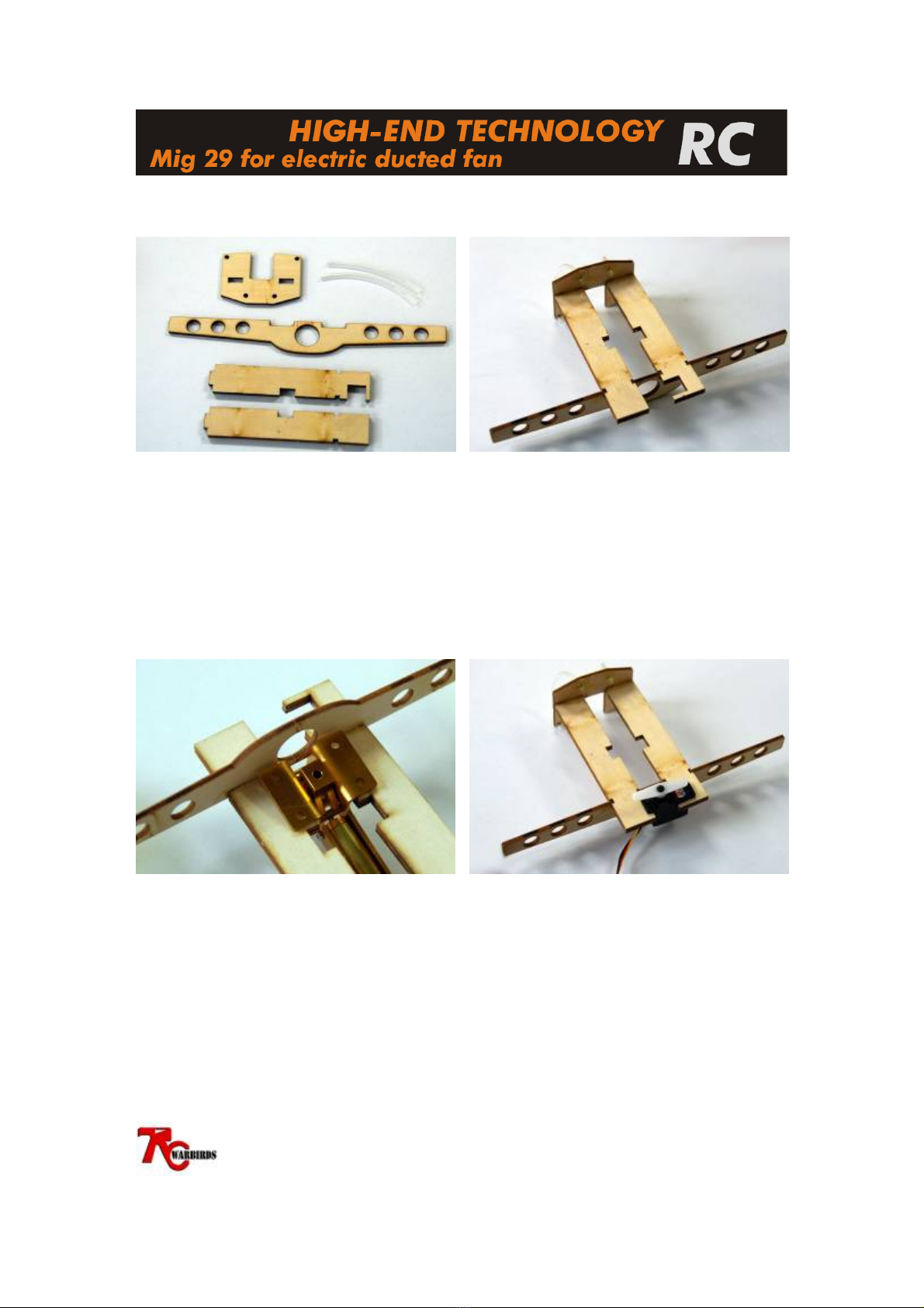
Step 1: Nose retract preparation
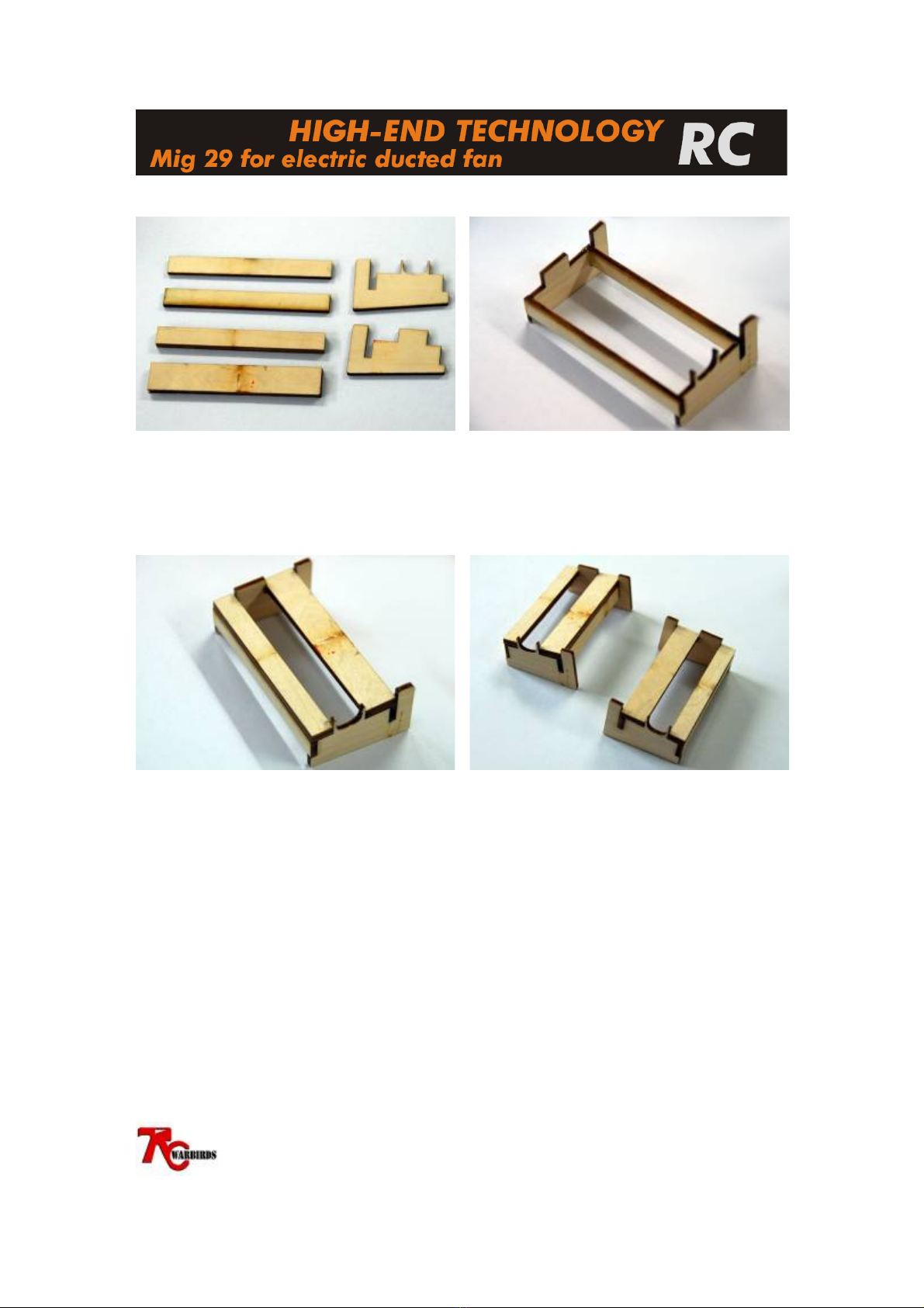
The nose retract mount consists out of the
parts shown above.
In addition to the ply formers included in
the kit please cut two 7cm long pieces from
the airtube included in the HET-RC Mini
Air Retract System set.
Dry fit the ply parts together as shown in
the picture above. Take care that the retract
mounting plates are installed in the correct
direction. The 2 airtubes are inserted into
the 2 holes at the back of the main retract
former and will form an arc from above the
retract mounting plate to the bottom on
each side. Roughen the airtube with
sandpaper and glue all parts with 30min
epoxy.
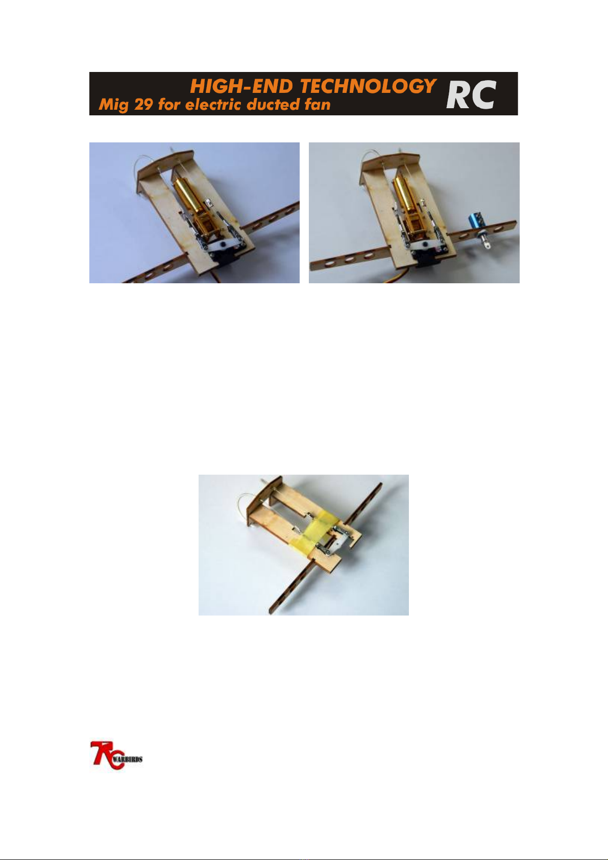
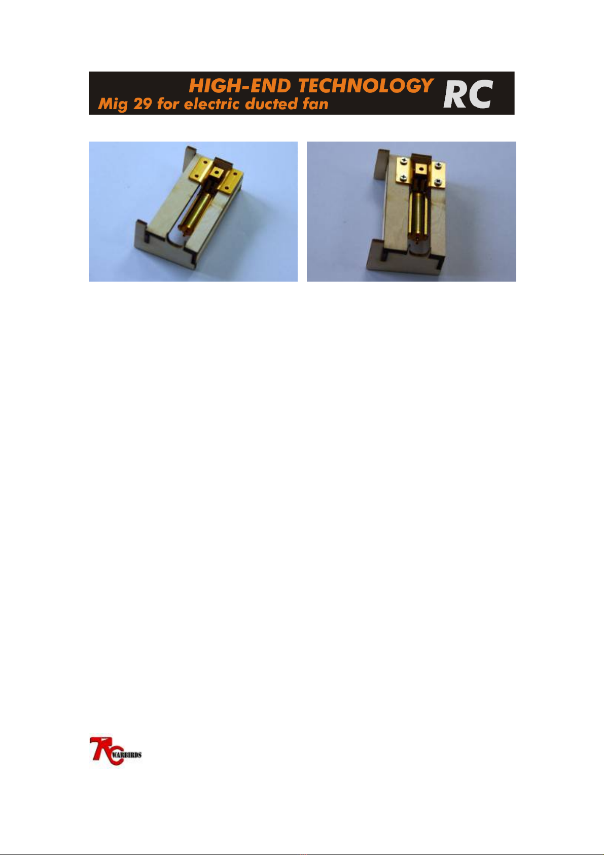
Once the glue has dried, test fit the nose
retract unit and mark the mounting hole
positions. Remove the retract unit and drill
4x 2mm holes at the marked positions.
Turn the mount around and test fit the nose
gear steering servo as shown above. The
servo arm is shown in its center position.
Mark the servo mounting hole locations,
remove the servo and drill the holes to the
size required for your servo (e.g. HS-65HB
1mm hole).
JOINTLY DEVELOPED WITH
WWW.RC-WARBIRDS.COM Page 5/16
Once all holes are drilled install both
retract unit and steering servo. Install the included nose gear wire and
steering arm. Both items need to be
removed again later so do not tighten them
to much.
Cut 2x 40cm from the supplied pull-pull
cable and pull one through each of the
airtubes installed in the retract mount. Next
slide one of the supplied crimp rings over
the wire and loop the wire through the
steering arm. After that pull the end of the
pull-pull cable through the crimp ring a
second time.
For a stronger hold loop the end of the pull-
pull wire one more time from the front
through the crimp ring. Squeeze the crimp
ring together with pliers. Test that the wire
is firmly crimped in place by pulling on the
pull-pull wire behind the crimp ring.
Repeat this step with the second pull-pull
wire.
JOINTLY DEVELOPED WITH
WWW.RC-WARBIRDS.COM Page 6/16
Turn the retract unit around and install the
pull-pull wire through the threaded
couplers as described in the previous steps.
Ensure that the couplers are fixed far
enough back to allow slop free but not to
tight fit between the pull-pull wire and the
servo.
Test the retract operation and adjust the
pull-pull wire tension to allow the retract to
fully lock in retract down position.
A drop of silicon oil (e.g. from RC-Heli
ball bearings) can be used to lubricate the
cable running through the airtube. This will
reduce steering cable friction.
Depending on the final model setup and
required weight distribution for the correct
center of gravity (CG) the retract valve can
be installed into the model at a later stage
as shown above or with the separate valve
holder supplied with the Mini Air Retract
set.
Remove servo, retract unit and valve from the mount and secure the steering cable, Servo
and retract steering arm with some masking tape in place.
The nose retract mount is now ready to be installed in the plane.
JOINTLY DEVELOPED WITH
WWW.RC-WARBIRDS.COM Page 7/16
Step 2: Main retract preparation
Each main retract former consists out of the
parts shown above. Before you begin
please read through this section and dry fit
all components.
NOTE: ensure that you build one right and
one left side retract mount.
Slot the 4x 3mm ply wood parts together as
shown above and glue with 30min epoxy.
Notice the difference between the 2 main
formers
Install the 4mm retract mounting plates as
shown above and glue with 30min epoxy
(apply the 30min epoxy to all areas that
have contact with the mounting plates).
Repeat the steps above for the 2nd retract
mount.
IMPORANT: Ensure to build one left and
one right hand side retract mount.
JOINTLY DEVELOPED WITH
WWW.RC-WARBIRDS.COM Page 8/16
Once all parts are dry, fit the retract unit
and mark the position of the mounting
holes. Ensure that the retract cylinder
points towards the former with the wire cut
out as shown above.
Drill the retract mounting holes (2mm drill)
and secure the retract unit in place.
Remove the retract unit. The main retract
mounting plates are now ready for
installation in the fuselage.
JOINTLY DEVELOPED WITH
WWW.RC-WARBIRDS.COM Page 9/16
Step 3: Retract cut outs
Before the retract mounts can be installed in the fuselage the necessary retract cut outs
have to be made in the fuselage.
We recommend to use a Dremel cutting disk and drum sander to make the necessary cuts.
NOTE:
As this process creates very fine epoxy/glass dust, the cutting has to be done in a well
ventilated area. The use of safety gear including gloves, safety glasses and surgical mask
is highly recommended.
Main Retract Units
The above cut out hast to be made for the main retract unit. Mirror the template for the
opposite side.
Before the retract slot can be cut, the
cutting area needs to be marked. Masking
tape does this job very well.
First measure 5mm forward (towards the
planes nose) from the main wing spar.
The retract slot will be cut between the
outer wing mounting wall and the air duct
towards the center of the fuselage. Leave
around 5mm between wing mounting wall
and retract cut out. The inner cut can be
made at the point where the air duct meets
the main fuselage body. Measure 3cm
(30mm) from the position marked in the
previous step towards the nose of the plane.
JOINTLY DEVELOPED WITH
WWW.RC-WARBIRDS.COM Page 10/16
Mask the remaining area as shown above and in the template.
(The cut out shown is from the right hand side of the model viewed from below)
Cut the marked area with a Dremel cutting
disk and drum sander. Sand round edges
where possible and avoid cutting into the
main spar.
Before the retract mount can be installed it
might be necessary to remove some of the
excess glue around the wing spar and
fuselage sides. In order to see if this is
necessary, slot the main retract unit through
the cockpit into the fuselage and position it
in place (use the correct side).
Remove excess glue where required until
you get a proper fit of the retract mount
against main spar and fuselage wall (where
the wing meets the fuselage).
Ensure not to damage the main spar.
Roughen the inside of the fuselage at the
glue areas with sandpaper.
Glue to main retract mount in place with
30min Epoxy and milled fiberglass. Use a
spanner to hold the mount in place until the
epoxy has cured.