RCA DHG535 User manual

CABLE SATELLITE TELECOM TERRESTRIAL
DHG535 - DATA & VOICE GATEWAY
User manual

Illustrations contained in this document are for representation only.
i
CAUTION
Disconnect power before
servicing.
This device is intended for
indoor operation only.
Telephone jacks Line 1 and
Line 2 must not be
connected to outside
wiring.
CAUTION
To ensure reliable operation and to prevent
overheating, provide adequate ventilation for this
modem and keep it away from heat sources. Do not
locate near heat registers or other heat-producing
equipment. Provide for free air flow around the
Residential Voice Gateway and its power supply.
NORTH AMERICAN CABLE INSTALLER:
This reminder is provided to call your attention to Article 820-40 of the National Electrical Code
(Section 54 of the Canadian Electrical Code, Part 1) which provides guidelines for proper
grounding and, in particular, specifies that the cable ground shall be connected to the
grounding system of the building as close to the point of cable entry as practical.
PacketCable and DOCSIS compliant
The RCA DHG535 is a residential gateway product, which provides broadband Internet access and
telephone capability all in one unit! Also referred to as an Embedded Media Terminal Adapter
(EMTA), this residential gateway connects to cable systems using DOCSIS and PacketCable standards.
(Check with your cable operator for compatibility.)
The RCA DHG535 offers a high-speed connection to the Internet using a USB or Ethernet connection.
If you have subscribed to telephone service from your cable operator, then you will be able to place
regular phone calls using your home phone(s) and/or fax machine. The RCA DHG535 provides two
RJ-11 connectors for your phone or home phone system, allowing one or two line service.
Operating Information
Operating Temperature: 0˚- 40˚C (32˚- 104˚F)
Storage Temperature: -20˚to 70˚C (-4°F to 158°F)
Humidity: up to 90% non-condensing

Illustrations contained in this document are for representation only.
ii
If you purchased this product at a retail outlet, please read the following:
Product Information
Keep your sales receipt to obtain warranty parts and service and for proof of purchase. Attach it
here and record the serial and model numbers in case you need them. The numbers are located
on the back of the product.
Model No. ____________________________Serial No ________________________________
Purchase Date: ________________________Dealer/Address/Phone: _________________________

Chapter 2: Advanced Information
Illustrations contained in this document are for representation only.
iii
Chapter 1: Connections and Setup
Introduction ............................................................................................................................ 1
EMTA Features .................................................................................................................. 1
What’s on the CD-ROM ...................................................................................................... 2
Computer Requirements.................................................................................................... 3
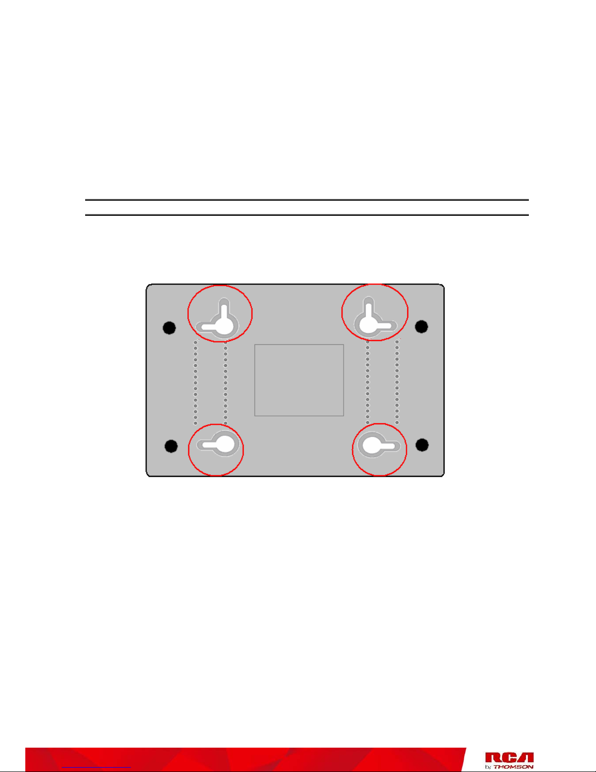
Wall Mounting ................................................................................................................... 4
Overview ................................................................................................................................. 5
Front Panel........................................................................................................................ 5
Rear Panel ......................................................................................................................... 7
Installing the Battery ......................................................................................................... 7
Clearance .......................................................................................................................... 8
Relationship among the Devices .............................................................................................. 9
What the EMTA Does ......................................................................................................... 9
What the EMTA Needs to Do Its Job ................................................................................... 9
Contact Your Local Cable Company ................................................................................. 10
Connecting the EMTA to a Single Computer ........................................................................... 12
Attaching the Cable TV Wire to the EMTA ........................................................................ 12
Important Connection Information .................................................................................. 13
USB Connection to One Computer ................................................................................... 13
USB Connection............................................................................................................... 14
Using Windows 2000 for USB Connection ........................................................................ 15
Using Windows Me for USB Connection............................................................................ 18
Using Windows XP for USB Connection ............................................................................ 19
Using Windows Vista for USB Connection......................................................................... 21
Follow steps 6 through 11 if you have a Windows Vista operating system:....................... 21

Chapter 2: Advanced Information
Illustrations contained in this document are for representation only.
iv
Ethernet Connection to One Computer ............................................................................ 25
Connecting More Than Two Computers to the EMTA ....................................................... 26
Telephone or Fax Connection.......................................................................................... 27
Activating the EMTA .............................................................................................................. 28
Accessing the Internet ........................................................................................................... 28
Basic Status Web Page Group ................................................................................................. 29
Basic LAN ........................................................................................................................ 29
Hardware Info ................................................................................................................. 30
Event Log ........................................................................................................................ 30
CM State ......................................................................................................................... 31
Frequently Asked Questions .................................................................................................. 32
General Troubleshooting ....................................................................................................... 33
FCC Declaration of Conformity and Industry Canada Information ........................................... 35
Service Information................................................................................................................ 36
Glossary ................................................................................................................................37

Chapter 2: Advanced Information
Illustrations contained in this document are for representation only.
1
Introduction
EMTA Features
zCableLabs DOCSIS 1.0/1.1/2.0 and PacketCable 1.0/1.1 Standard Compliant
zSupport Multiple Provisioning Mode
zSupport PacketCable NCS 1.0 MGCP1.0 (Media Gateway Control Protocol)
zStandard RJ-45 connector for 10/100BaseT Ethernet with auto-negotiation and MDIS
functions
zUSB Connector for USB interface
zTwo RJ-11 Foreign Exchange Station (FXS) ports for IP telephony
zSupport simultaneous voice and data communications
zTwo simultaneous voice conversations in the different FXS ports with different CODEC:
PCM A-law, PCM -law, G.723.1, G.729, G.729a, G.729e, G.728, G.726, BV16 and
BV32.
zEcho Cancellation
zVoice Active Detection (VAD)
zDTMF detection and generation
zComfort Noise Generation (CNG)
zSupport V.90 fax and modem services
zTransparent bridging for IP traffic
zRSA and 56 bit DES data encryption security
zSNMP network management support
zRemote operating firmware downloading
zSupport Web pages and private DHCP server for status monitoring
zClear LED display
zPlug and Play
zSupport maximum two battery packs (Optional)

Chapter 2: Advanced Information
Illustrations contained in this document are for representation only.
2
What’s on the CD-ROM
Insert the EMTA CD-ROM into your CD-ROM drive to view troubleshooting tips, the internal
diagnostics, and other valuable information.
Note: You might need to use the CD-ROM to install the USB driver if you are connecting via the
USB port.
CD-ROM Contents:
zElectronic copy of this user’s guide in additional languages (PDF format)
zAdobe Acrobat Reader — application you can load to read PDF format, if you don’t have
it loaded already
zUSB drivers — required if connecting by USB
zLinks to Thomson and RCA web sites
DOCSIS and PacketCable are trademarks of Cable Television Laboratories, Inc.

Chapter 2: Advanced Information
Illustrations contained in this document are for representation only.
3
Computer Requirements
For the best possible performance from your EMTA, your personal computer must meet the
following minimum system requirements (note that the minimum requirements may vary by
cable companies):
IBM PC COMPATIBLE MACINTOSH**
CPU Pentium preferred PowerPC or higher
System RAM 16MB (32MB preferred) 24MB (32MB preferred)
Operating System Windows* NT/2000/Me/XP/Vista
Linux
Mac OS** 7.6.1 or higher
Sound Card Required for audio on CD-ROM N/A
Video VGA or better (SVGA preferred) VGA or better (SVGA built-in preferred)
CD-ROM Drive Required Required
10BaseT or 100BaseT 10BaseT or 100BaseTEthernet
An Ethernet card makes it possible for your computer to pass data to and
from the internet. You must have an Ethernet card and software drivers
installed in your computer. You will also need a standard Ethernet cable to
connect the Ethernet card to your EMTA
USB (Windows 2000/ME/XP/Vista only)USB Port
The Universal Serial Bus is a high speed bus that enables your computer
to communicate simultaneously with a variety of peripherals. However, if
you have other peripherals that send and receive a lot of information,
such as speakers, printers or scanners, we recommend using an Ethernet
card to support this modem.
Software •A TCP/IP network protocol for each machine
•Microsoft Internet Explorer 4.0 or later or Netscape Navigator 4.0 or
later. (5.0 and 4.7 or later, respectively, are strongly recommended.)
*Windows is a trademark of Microsoft Corporation.
**Macintosh and the Mac OS are trademarks of Apple Computer, Inc.

Chapter 2: Advanced Information
Illustrations contained in this document are for representation only.
4
Wall Mounting
The number of the screw: 2 pcs
Direction for wall mounting: LED panel upward.
Dimension for the screw: TBD
There are 4 slots on the underside of the EMTA that can be used for wall mounting.
Note: When wall mounting the unit, ensure that it is within reach of the power outlet.
You will need 2 suitable screws which screw diameter would be 4.4 mm to wall mount the Cable
Modem or the Battery Pack. Two different wall mount directions could be chosen for the Battery
Pack.
To do this:
1. Ensure that the wall you use is smooth, flat, dry and sturdy and use the 4 screw holes
which are 101.6 mm apart from each other.
2. Fix the screws into wall, leaving their heads 3 mm (0.12 inch) clear of the wall surface.
3. Remove any connections to the unit and locate it over the screw heads. When in line,
gently push the unit on to the wall and move it downwards to secure.

Chapter 2: Advanced Information
Illustrations contained in this document are for representation only.
5
Overview
Front Panel
The following illustration shows the front panel:
The LEDs on the front panel are described in the table below (from left to right):
Internet
DHG535 Power DS US Online Link Tel 1 Tel 2 Battery Description
ON ON ON ON
ON 0.25 second ON ON ON X Power on 0.25 sec
ON FLASH FLASH FLASH X X X X From power ON to system
initialization complete
ON ON ON
Boot-up
Operation
ON 1 second X X X X
Following system
initialization complete to
(before)
DS scanning
ON FLASH OFF OFF X X X X During DS scanning and
acquiring SYNC
ON ON FLASH OFF X X X X From SYNC completed,
receiving UCD to ranging
completed
ON ON ON FLASH X X X X
During DHCP, configuration
file download, registration,
and Baseline Privacy
initialization
ON ON ON ON X X X X Operational (NACO=ON)
DOCSIS
Start-up
Operation
ON FLASH FLASH OFF X X X X Operational (NACO=OFF)
ON ON ON ON X FLASH OFF OFF MTA DHCP
ON ON ON ON X OFF FLASH OFF MTA SNMP/TFTP
MTA
initialization ON ON ON ON X FLASH FLASH OFF RSIP
ON X X X OFF
ON
FLASH X X X No Ethernet Link
Ethernet Link
TX/RX Ethernet Traffic
CPE
Operation ON X X X OFF X X X No USB Link

Chapter 2: Advanced Information
Illustrations contained in this document are for representation only.
6
Internet
DHG535 Power DS US Link Tel 1 Tel 2 Battery Description
Online ON
FLASH USB Link
TX/RX USB Traffic
ON ON ON Both Lines On-Hook
ON FLASH ON Tel1 Off-hook, Tel2
On-hook
ON ON FLASH Tel1 On-hook, Tel2
Off-hook
AC Good
Battery
Good
ON FLASH FLASH
ON
Both Lines Off-Hook
ON ON ON Both Lines On-Hook
ON FLASH ON Tel1 Off-hook, Tel2
On-hook
ON ON FLASH Tel1 On-hook, Tel2
Off-hook
AC Good
Battery Low
ON FLASH FLASH
FLASH
Both Lines Off-Hook
ON ON ON Both Lines On-Hook
ON FLASH ON Tel1 Off-hook, Tel2
On-hook
ON ON FLASH Tel1 On-hook, Tel2
Off-hook
AC Good
Battery Bad
ON
<CM Normal Operation>
FLASH FLASH
OFF
Both Lines Off-Hook
ON Both Lines On-Hook
FLASH Tel1 Off-hook, Tel2
On-hook
ON Tel1 On-hook, Tel2
Off-hook
AC Fail
Battery
Good
FLASH
OFF
Both Lines Off-Hook
ON Both Lines On-Hook
FLASH Tel1 Off-hook, Tel2
On-hook
ON Tel1 On-hook, Tel2
Off-hook
AC Fail
Battery Low
FLASH OFF
FLASH
FLASH
Both Lines Off-Hook
Both Lines On-Hook
Tel1 Off-hook, Tel2
On-hook
Tel1 On-hook, Tel2
Off-hook
AC Fail
Battery Bad < All LEDs may be unlit due to lack of battery
power>
OFF
OFF
Both Lines Off-Hook
SW
Download
Operation ON FLASH FLASH ON X X X X A software download and
while updating the FLASH
memory

Chapter 2: Advanced Information
Illustrations contained in this document are for representation only.
7
Rear Panel
Connector Description
100-240 VAC Power connector
REBOOT EMTA Reset EMTA
TEL 1/2 and TEL 2 RJ-11 Phone set connector
ETHERNET Ethernet 10/100BaseT RJ-45 connector
USB USB Connector
CABLE F-Connector
Installing the Battery
This section provides information on installing batteries into the EMTA. Follow the steps
below:
1. Ensure the power cord is unplugged.
2. Remove the battery cover on the rear panel. There are two battery
compartments. You may install a single battery into either compartment.

Chapter 2: Advanced Information
Illustrations contained in this document are for representation only.
8
3. Insert the battery into one of the rear battery compartments, as shown below.
4. Reattach the battery cover.
5. Plug the power cord into an AC-receptacle that is always ON (non-switchable). The
battery will fully charge within 4 hours.
Clearance
When installed at normal room temperatures and desktop locations, a minimum of 1"
clearance should be maintained around the unit to allow for ventilation. When installed in
areas like utility closets where temperatures might exceed 100 degrees F, then 4"
clearance is required around the unit. This product is not designed for operation above
122 degrees F.

Chapter 2: Advanced Information
Illustrations contained in this document are for representation only.
9
Relationship among the Devices
This illustration shows a cable company that offers DOCSIS- and PacketCable-compliant
voice/data services.
What the EMTA Does
The EMTA provides high-speed Internet access as well as cost-effective, toll-quality telephone
voice and fax/modem services over residential, commercial, and education subscribers on
public and private networks via an existing CATV infrastructure. It can inter-operate with the
PacketCable compliant headend equipment and provide the IP-based voice communications.
The IP traffic can transfer between the EMTA and DOCSIS compliant headend equipment. The
data security secures upstream and downstream communications.
What the EMTA Needs to Do Its Job
The Right Cable Company: Make sure your local cable company provides data services
that use cable TV industry-standard Euro-DOCSIS or DOCSIS-compliant and
Euro-PacketCable or PacketCable-compliant technology.
The Internet/Telephony Service Provider (ISP/TSP): Your cable company provides you
access to an Internet Service Provider (ISP) and Telephony Service Provider (TSP). The ISP is
your EMTA to the Internet and provides you with a pipeline to access Internet content on the

Chapter 2: Advanced Information
Illustrations contained in this document are for representation only.
10
World Wide Web (WWW). The TSP provides you with telephony access to other modems or
other telephony services over the Public Switched Telephone Network (PSTN).
Check with your cable company to make sure you have everything you need to begin; they’ll
know if you need to install special software or re-configure your computer to make your cable
internet service work for you.
Contact Your Local Cable Company
You will need to contact your cable company to establish an Internet account before you can use
your EMTA. You should have the following information ready (which you will find on the sticker
on the EMTA):
•The serial number
•The model number
•The Cable Modem (CM) Media Access Control (MAC) address
•The Terminal Adapter (EMTA) MAC address

Chapter 2: Advanced Information
Illustrations contained in this document are for representation only.
11
Please verify the following with the cable company
The cable service to your home supports Euro-DOCSIS or DOCSIS compliant two-way
modem access.
Your internet account has been set up. (The Media Terminal Adapter will provide data
service if the cable account is set up but no telephony service is available.)
You have a cable outlet near your PC and it is ready for Cable Modem service.
Note: It is important to supply power to the modem at all times. Keeping your modem plugged in
will keep it connected to the Internet. This means that it will always be ready whenever you
need.
Important Information
Your cable company should always be consulted before installing a new cable outlet. Do not
attempt any rewiring without contacting your cable company first.

Chapter 2: Advanced Information
Illustrations contained in this document are for representation only.
12
Connecting the EMTA to a Single Computer
This section of the manual explains how to connect your EMTA to the USB or Ethernet port on
your computer and install the necessary software. Please refer to Figure 1 to help you connect
your Digital Cable Modem for the best possible connection.
Attaching the Cable TV Wire to the EMTA
1. Locate the Cable TV wire. You may find it one of three ways:
a. Connected directly to a TV, a Cable TV converter box, or VCR. The line will be
connected to the jack which should be labeled either IN, CABLE IN, CATV, CATV IN, etc.
b. Connected to a wall-mounted cable outlet.
c. Coming out from under a baseboard heater or other location. See Figure 1 for the
wiring example.
Notes: For optimum performance, be sure to
connect your EMTA to the first point the cable
enters your home. The splitter must be rated for
at least 1GHz.
Fig. 1: Basic Home Wiring

Chapter 2: Advanced Information
Illustrations contained in this document are for representation only.
13
Important Connection Information
The EMTA supports Ethernet and USB connections simultaneously.
Below are important points to remember before you connect the EMTA.
For USB connections, follow the instructions on this page.
For Ethernet connections, go to page 21.
For telephone and fax connections, go to page 23.
USB Connection to One Computer
Note: Only use the power
supply provided with this
unit. Using other power
supplies may damage the
unit.
Fig. 2: USB Connection

Chapter 2: Advanced Information
Illustrations contained in this document are for representation only.
14
If you received an Installation/Quick Start kit with the purchase of your modem, you should use
the software provided in that kit. If not, the EMTA CD included with your modem contains the
drivers and other information you need to install your EMTA.
USB Connection
If you do not want to use the CD-ROM, follow instructions 1 through 5 to connect the EMTA to
the USB port on your computer. Instructions must be followed in the order they appear.
1. Connect one end of the coaxial cable to the cable connection on the wall, and the other end to
the CABLE jack on the EMTA.
2. Connect the plug from the AC power supply into the POWER AC ADAPTER jack on the EMTA
and plug the power supply into an AC outlet.
3. Insert the supplied EMTA CD-ROM. Wait momentarily for the CD window display.
4. Close all open applications and dialog boxes, including the CD window.
Note: Some applications may interfere with your EMTA installation.
5. Connect one end of the USB cable to the USB port located on the back of your computer.
Connect the other end of the USB cable to the USB port on the EMTA.
Note: Use only the power supply that accompanied this unit. Using other power supplies may
damage the unit.
Next, you need to install the USB driver for your operating system.

Chapter 2: Advanced Information
Illustrations contained in this document are for representation only.
15
Using Windows 2000 for USB Connection
Follow steps 6 through 14 if you have a Windows 2000 operating system:
6. When the “Found New Hardware Wizard” appears, click “Next” to initiate the search for drivers
for your USB device.
Note: If Windows 2000 does not recognize the presence of the EMTA, your BIOS settings may
not permit USB and/or Plug-and-Play devices. Please contact the customer service department
of the computer company.
7. Choose the “Search for a suitable driver for my device (recommended)” option, and click
“Next”.
Table of contents
Other RCA Gateway manuals