6TL YAV90090 User manual

Creation Date 24/07/18
Modification Date 01/07/2022
Ethernet to CAN Gateway
YAV90090
YAV90090CM000E06

2
Ethernet to CAN Gateway YAV90090 620090E04
Thistechnicalinformationhasbeenproduced,written,andcheckedensuringthegreatest
accuracyandsimplification. If despite this, you find a mistake or a detail which could
contribute to improving the product or its documentation, we would appreciate you
informing us of it. Your contribution will be well received.
6TL Engineering
Registered Trademark by S.A. Sistel
in class 9 with Nº M-1780187
Copyright © 6TL Engineering 2022. All Rights
Reserved.
6TL Engineering hardwareandsoftwareproductsarecoveredbynationaland
internationalpatentsand/orCopyright©orwithpatents pending for models and
trademarks presented. Any violation of the intellectual property rights will be
prosecuted with all legal means available.
Solsones, 87 E-08211 CASTELLAR (Barcelona)

3
Ethernet to CAN Gateway YAV90090 620090E06
This manual is related to the following product:
Product –P/N
YAV90090
Hardware version
02
Software version
02
Issued date
14/10/2017
Product Versions
Hard
Soft
Submission Date
Content changes
02
01
10/2017
First release
02
02
01/2022
Added Multicast and bootloader functionality
Document Log
Revision
Submission Date
Content changes
E01
07/2018
First release
E02
13/11/2018
E03
19/02/2019
Firewall rules explained
E04
12/01/2022
New SW2 functionality
E05
25/02/2022
Corrected errors in SW2 description
E06
30/06/2022
Extended SW2 description.

4
Ethernet to CAN Gateway YAV90090 620090E06
Table of Contents
1Acronyms............................................................................................................ 5
2Before you begin.............................................Error! No s'ha definit el marcador.
3Safety ...............................................................Error! No s'ha definit el marcador.
Symbols and safety terms...................Error! No s'ha definit el marcador.
Precautions against damage to peopleError! No s'ha definit el marcador.
Precautions against damage to the productError! No s'ha definit el
marcador.
4Limits of the guarantee...................................Error! No s'ha definit el marcador.
5Certifications ...................................................Error! No s'ha definit el marcador.
6General Description........................................................................................... 6
Features .................................................................................................... 7
6.1.1 General ................................................................................................................... 7
6.1.2 LAN properties........................................................................................................ 7
6.1.3 CAN properties:....................................................................................................... 7
Applications ............................................................................................... 7
Purchase order information........................................................................ 7
Delivery scope........................................................................................... 7
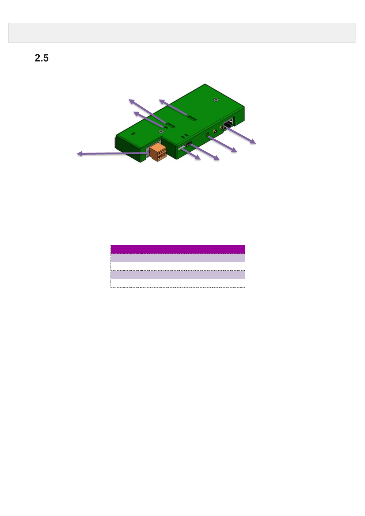
Connectors ................................................................................................ 8
6.5.1 CAN......................................................................................................................... 8
6.5.2 CAN End Jumper.................................................................................................... 8
6.5.3 LAN ......................................................................................................................... 8
6.5.4 USB Port.........................................................Error! No s'ha definit el marcador.
6.5.5 Boot button......................................................Error! No s'ha definit el marcador.
6.5.6 Mode Dip switch SW2............................................................................................. 9
6.5.6.1 Unicast mode....................................................................................................................... 10
6.5.6.2 Multicast mode..................................................................................................................... 10
6.5.7 Speed and Address switch SW1........................................................................... 13
Operation................................................................................................. 14
6.6.1 Preparing the computer ........................................................................................ 14
6.6.2 Establishing the connection ..................................................................................15
6.6.3 Prepare Phi6 Explorer...........................................................................................15
6.6.3.1 UDP Unicast connection....................................................................................................... 15
6.6.3.2 UDP Multicast connection .................................................................................................... 15
Dimensions.............................................................................................. 16
7Appendix A. Factory Labelling........................................................................ 17
8Appendix B. Troubleshooting......................................................................... 18
9Appendix C. Figure list.................................................................................... 18

5
Ethernet to CAN Gateway YAV90090 620090E06
1 Acronyms
Term
Meaning
DUT
Device Under Test
DHCP
Dynamic Host Configuration Protocol

6
Ethernet to CAN Gateway YAV90090 620090E06
2 General Description
The YAV90090 module, allows the exchange of CAN messages between CAN systems
via TCP/IP, using existing Ethernet infrastructures.
Thanks to the Gateway, the user can control the 6TL modules (which feature CAN bus
communication), through TCP/IP from a PC.
CAN frames are wrapped in TCP or UDP message packets and then forwarded via the
IP network.
The YAV90090 Gateway provides one LAN connection and one High-speed CAN
interface. The module is suitable for use in an industrial environment.
The YAV90090 Gateway module is configured via easily accessible dip switches.

7
Ethernet to CAN Gateway YAV90090 620090E06
Features
2.1.1 General
▪High-performance Arm Cortex-M3 MCU with 512 Kbytes Flash, 120 MHz CPU,
ART Accelerator, Ethernet P/N STM32F207IEH6
▪Connections for CAN, and power supply via 4-pole Weidmüller connector
▪Reboot and reset of the device to factory defaults with a reset button
▪Plastic casing for benchtop operation
▪LEDs for device status and power supply
▪Voltage supply from 8 to 30 V
2.1.2 LAN properties
▪Data transmission using TCP or UDP
▪Single Port Ethernet Physical Layer Transceiver P/N DP83848CVV
▪10/100 Mbit/s bit rate
▪RJ-45 connector with status LEDs
2.1.3 CAN properties:
▪One High-speed CAN channel
▪Bit rates from 5 kbit/s up to 1 Mbit/s
▪Infineon TLE6250GV3CAN transceiver
▪Compatible with 6TL modules CAN interface
Applications
▪Control of 6TL modules and YAV modules
Purchase order information
Description
P/N
Ethernet to CAN gateway
YAV90090
Delivery scope
Qty
Description
P/N
1
Ethernet to CAN Gateway
YAV90090
1
Operation Manual
6200 90Exx
1
Weidmuller connector for PSU and CAN
xxxx

8
Ethernet to CAN Gateway YAV90090 620090E06
Connectors
2.5.1 CAN
The CAN connector is a 4-pin Weidmüller 3,5” pitch.
Pin
Function
1
GND
2
+24V
3
CAN L
4
CAN H
The mating connector is aerial Weidmüller 1690210000
2.5.2 CAN End Jumper
The CAN network ends must be “closed” with a resistor to reduce echoes in signal pulses.
Only in the case that the physical position of the board in the CAN network is in the end
position, the jumper must be placed (Resistor joining CAN H and CAN L).
2.5.3 LAN
Connector RJ45 (22): Suitable for CAT 5&6 Fast Ethernet Cable. Meets IEEE 802.3
standard for 100 Base-T.
The purpose of this port is to configure the device as an Ethernet control.
X1: CAN
RUN Led
SW 1: CAN speed
and address
LAN address
settings
CAN end
Resistor
USB 2.0 port
(Factory use)
Boot
LAN

9
Ethernet to CAN Gateway YAV90090 620090E06
The cabling for this connector should be constructed according to the characteristics
described:
Description
Value
Nom. Diff. Characteristic Impedance
100 ohms (+10 ohms, -15 ohms)
Nom. Inductance @ 10 kHz
0.47 uH/meter
Nom. Capacitance –Conductor To Conductor @
10 kHz
41.0 pF/meter
Nom. Capacitance –Conductor To Other
Conductor & Shield @ 10 kHz
65.6 pF/meter
Nom. Velocity of Propagation
74%
Nom. Conductor DC Resistance @ 20C
14.57 ohms / 100 meters
Nom. Outer Shield DC Resistance @ 20C
1.7 ohms / 100 meters
Max. Operating Voltage –UL
30 V RMS
Pin
Function
1
Tx+
2
Tx-
3
Rx+
4
-
5
-
6
Rx-
7
-
8
-
2.5.4 Mode Dip switch SW2
With the DIP switch 2 the user can change the IP address from the device, select if the
communication is unicast or multicast, change the IP multicast address and select to use
the default Ethernet settings or to use the user configured settings.
By default, YAV90090 will have the following IP addresses:
•IP address: 192.168.18.55
•Net mask: 255.255.255.0
•Gateway address: 192.168.18.10
•Multicast IP address: 224.0.0.5
NOTE: YAV90090 can handle any other IP configuration, contact with 6TL
Engineering for more information.

10
Ethernet to CAN Gateway YAV90090 620090E06
2.5.4.1 Unicast mode.
The unicast communication mode is a data transmission from a single module to a single
receiver.
This mode is recommended when there is only one gateway, a single ethernet bus and
only one computer.
The unicast mode is set when the DIP switch 8 is ON. Some examples on how the SW2
works when it is configured in Unicast mode:
SW2_1
SW2_2
SW2_3
SW2_4
SW2_5
SW2_6
SW2_7
SW2_8
SETTINGS
Offset to add to the default IP. (55 to 86)
Not
used
Use Default
IP settings
Select Multicast
or Unicast mode
LSB
MSB
OFF
OFF
OFF
OFF
OFF
X
OFF
ON
Unicast communication with
IP address: 192.168.18.55
ON
OFF
OFF
OFF
OFF
X
OFF
ON
Unicast communication with
IP address: 192.168.18.56
ON
ON
ON
ON
ON
X
OFF
ON
Unicast communication with
IP address: 192.168.18.86
X
X
X
X
X
X
ON
ON
Unicast communication with
IP address: 192.168.18.55
With these settings the IP address can be configured from 192.168.18.55 to
192.168.18.86.

11
Ethernet to CAN Gateway YAV90090 620090E06
2.5.4.2 Multicast mode.
The multicast communication mode is a data transmission from a single module to
multiple receivers. Multicast is like broadcast communication mode, but only transmits
the message to specific users.
Multicast transmission has some IP addresses range reserved, from the 224.0.0.0 to
239.255.255.255. The specific users connect to one of these IP addresses and they
create a group. When a message is sent to this IP address, all the users that are joined
to the same group receive the message.
The Multicast mode is recommended in several scenarios:
•When there are different gateways connected to a single ethernet bus and a single
computer.
•When there is one gateway connected to a single ethernet bus and multiple
computers.
•When there are multiple gateways connected to a single ethernet bus and multiple
computers.
The unicast IP addressmust be different from onedevice to another device. For example,
if an ethernet bus is connected to 2 YAV90090 and one computer, all 3 devices will be
connected to the same multicast group address, with the IP address 224.0.0.5, but the
YAV90090_1 will have the IP address 192.168.18.55, the YAV90090_2 will have the IP
address 192.168.18.56 and the computer will have the IP address 192.168.18.10.
The Multicast mode is set when the DIP switch 8 is OFF. Some examples on how the
SW2 works when it is configured in Multicast mode:

12
Ethernet to CAN Gateway YAV90090 620090E06
SW2_1
SW2_2
SW2_3
SW2_4
SW2_5
SW2_6
SW2_7
SW2_8
SETTINGS
Offset to add to the default IP. (0 to 31)
Not
used
Use Default
IP settings
Select Multicast
or Unicast mode
LSB
MSB
OFF
OFF
OFF
OFF
OFF
X
OFF
OFF
Multicast communication
with IP address:
192.168.18.55 and Multicast
address: 224.0.0.5
ON
OFF
OFF
OFF
OFF
X
OFF
OFF
Multicast communication
with IP address:
192.168.18.56 and Multicast
address: 224.0.0.6
ON
ON
ON
ON
ON
X
OFF
OFF
Multicast communication
with IP address:
192.168.18.86
X
X
X
X
X
X
ON
OFF
Multicast communication
with IP address:
192.168.18.55 and Multicast
address: 224.0.0.5

13
Ethernet to CAN Gateway YAV90090 620090E06
2.5.5 Speed and Address switch SW1
CAN speed and address setting:
Switch
50 kB/s
100 kB/s
125 kB/s
250 kB/s
0
Off
On
Off
On
1
Off
Off
On
On
The address code is added as suffix, completing the identifier. (See Phi6 Commands
chapter):
Switch
ON Weight
2
1
3
2
4
4
5
8
6
16
7
32

14
Ethernet to CAN Gateway YAV90090 620090E06
Operation
The YAV90090 Gateway is configured by the DIP switches. The module must be
connected via LAN to a computer, located in the same logical network as the gateway
(192.168.xxx.xxx).
2.6.1 Preparing the computer
Your computer must be configured with an appropriate IP address to connect to the
gateway via LAN. To determine your IP address and to change it if necessary, follow the
following steps:
1. Open the Windows Start menu.
2. Type ncpa.cpl and press Enter
The overview of the network adapters appears.
3. Do a right-click on the adapter that will be usedfor the connection to the YAV90090
Gateway and select Properties.
4. Open the properties of Internet Protocol Version 4 (TCP/IPv4).
5. Make a note of the current settings to reset the computer later on.
6. Select Use the following IP address.
7. Enter an IP address in the range from 192.168.18.1 to 192.168.18.254 (but not
the YAV90090's own address which is indicated on the left casing side).
8. Click on Subnet mask. 255.255.255.0 is shown. Leave this entry unchanged.
9. Enter a Default Gateway this IP address should be the YAV90090's own address.
10.Confirm the entries with OK.
It is necessary to create new rules in the windows firewall to allow the UDP connection
between the YAV90090 and the computer. To create a new the news rules, follow these
steps:
1. Open the Windows Start menu.
2. Type wf.msc and press Enter
The Windows Defender Firewall advanced settings appears.
3. In the navigation pane, click on Inbound Rules.
4. Click on Action, and then click on New Rule
5. On the Rule Type page of the New Inbound Rule Wizard, click Program and then
click next.
6. Copy this path on the program path: %ProgramFiles% (x86)\6TL\Phi6-
Explorer.exe

15
Ethernet to CAN Gateway YAV90090 620090E06
7. On the Action page, select Allow the connection and then click next.
8. On the Name page, type a name and a description and then click Finish.
2.6.2 Establishing the connection
1. Connect the RJ-45 connector of the YAV90090 via a LAN cable, directly to the
computer.
2. Connect the CAN cable to power up the module.
Power supply input voltage
VB
8
24
30
VDC
Current consumption at voltage input @+24VDC
IB
260
85
72
mA
3. Wait until the YAV90090 is ready (RUN led is blinking green).
4. To check if there is connection, open the command prompt and ping the YAV90090
IP address. For example: ping 192.168.18.55.
2.6.3 Prepare Phi6 Explorer
2.6.3.1 UDP Unicast connection
1. Locate the 6TL folder. It should be in the following directory:
“C:\Users\Public\Documents\6TL”.
2. Edit the “Phi6Config.ini” file. Add “//” fifth line and remove it from the sixth and
seventh line.
3. Write in the IP field your Default Gateway.
2.6.3.2 UDP Multicast connection
1. Locate the 6TL folder. It should be in the following directory:
“C:\Users\Public\Documents\6TL”.
2. Edit the “Phi6Config.ini” file. Add “//” fifth line and remove it from the sixth and
seventh line.
3. Write in the IP field your own IP address. And write in the IPMULTICAST field the
IP multicast group configured by the switches.

16
Ethernet to CAN Gateway YAV90090 620090E06
Dimensions

17
Ethernet to CAN Gateway YAV90090 620090E06
3 Appendix A. Factory Labelling
The module has internally a non-erasable Serial Number that is part of the MAC address.
When the final test is passed, the product is labelled in the solder side with a label P/N.
Indicating:
▪P/N
▪Description and hardware and software version
▪S/N
Figure 1: Board description label
In parallel, another Label P/N ... is generated and supplied with the protective liner to be
placed in the casing. This label will have the same contents:
▪Description and hardware/firmware version
▪P/N
▪S/N.
▪MAC address (OUI Id. + S/N coded Hex.)
Figure 2: Casing description label

18
Ethernet to CAN Gateway YAV90090 620090E06
4 Appendix B. Troubleshooting
Effect
Possible Cause
Solution
1
Everything looks fine, but I’m
not able to make the Gateway
work
Firewall may be cutting
communications
Open port 65534 in the
firewall (UDP protocol) to
make it work.
5 Appendix C. Figure list
Figure 1: Board description label.................................................................................. 17
Figure 2: Casing description label................................................................................. 17
Table of contents
Popular Gateway manuals by other brands

Ursalink
Ursalink urbana GI01 quick start guide

DEUTSCHMANN AUTOMATION
DEUTSCHMANN AUTOMATION UNIGATE RS232/485 instruction manual

MSI
MSI RG11B quick start guide

GE Security
GE Security NX-592E-GSM installation manual

WAGO
WAGO BACnet/IP Installation and service instructions

Zoom
Zoom X5V 1610 quick start guide