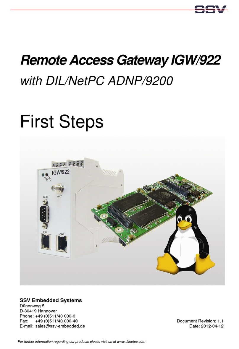
SSV IGW/922 Application guide

Remote Access Gateway IGW/922
with DIL/NetPC ADNP/9200
Hardware Reference
SSV Embedded Systems
Dünenweg 5
D-30419 Hannover
Phone: +49 (0)511/40 000-0
Fax: +49 (0)511/40 000-40
E-mail: sales@ssv-embedded.de Document Revision: 1.3
Date: 2012-04-12
F
OR FURTHER INFORMATION REGARDING OUR PRODUCTS PLEASE VISIT US AT WWW
.
SSV
-
EMBEDDED
.
DE

Remote Access Gateway IGW/922 - Hardware Reference
2
Board Revision 1.0 / Manual Revision 1.3
CONTENT
1INTRODUCTION...............................................................................................................3
1.1 Safety Guidelines...................................................................................................................3
1.2 Conventions...........................................................................................................................3
1.3 Features and Technical Data..................................................................................................4
1.4 Main Applications .................................................................................................................4
2OVERVIEW .......................................................................................................................5
3PINOUTS ..........................................................................................................................6
3.1 Screw Terminals ....................................................................................................................6
3.2 Ethernet LAN1 and LAN2.....................................................................................................7
3.3 Serial Port COM1 ..................................................................................................................7
4CONNECTIONS................................................................................................................8
4.1 Serial Port COM2 ..................................................................................................................8
4.2 Power Supply.........................................................................................................................9
4.3 Semiconductor Relay Output...............................................................................................10
5HELPFUL LITERATURE.................................................................................................11
CONTACT..............................................................................................................................11
DOCUMENT HISTORY .........................................................................................................11

Remote Access Gateway IGW/922 - Hardware Reference
Board Revision 1.0 / Manual Revision 1.3
3
1 INTRODUCTION
This document describes the hardware components and the necessary cable connections of
the Remote Access Gateway IGW/922.
1.1 Safety Guidelines
Please read the following safety guidelines carefully! In case of property or personal
damage by not paying attention to this document and/or by incorrect handling, we do
not assume liability. In such cases any warranty claim expires.
ATTENTION: Observe precautions for handling – electrostatic sensitive device!
•Discharge yourself before you work with the device, e.g. by touching a heater of
metal, to avoid damages.
•Stay grounded while working with the device to avoid damage through electrostatic
discharge.
1.2 Conventions
Convention Usage
bold
Important terms
italic
Filenames, user inputs and command lines
monospace Pathnames, internet addresses and program code
Table 1: Conventions used in this document

Remote Access Gateway IGW/922 - Hardware Reference
4
Board Revision 1.0 / Manual Revision 1.3
1.3 Features and Technical Data
•1x QIL-128 socket for DIL/NetPC ADNP/9200
•1x modem socket option for GSM/GPRS/UMTS/HSPA wireless modems
•2x 10/100 Mbps Ethernet LAN interface with status LEDs
•1x RS232 serial port (COM1) with handshake lines and 9-pin Sub-D connector
•1x RS232/485 serial port (COM2) with 3-pin screw terminal and software-selectable
mode switch
•1x semiconductor relay output (30 VDC, 500 mA)
•1x power LED
•1x user LED (programmable)
•Supply voltage 11 .. 28 VDC (typ. 24 VDC)
•Mechanical dimensions: 45 mm x 100 mm x 112 mm
•0 °C to +70 °C operating temperature
•RoHS conform
1.4 Main Applications
•Remote Access Security Gateway
•GPRS/UMTS Router

Remote Access Gateway IGW/922 - Hardware Reference
Board Revision 1.0 / Manual Revision 1.3
5
2 OVERVIEW
Figure 1: Overview Remote Access Gateway IGW/922

Remote Access Gateway IGW/922 - Hardware Reference
6
Board Revision 1.0 / Manual Revision 1.3
3 PINOUTS
3.1 Screw Terminals
The table 2 shows the pinout of the screw terminals of the IGW/922.
Pin
Power COM2 Alarm
RS232 RS485*
A1
Alarm -
A2
Alarm +
A3
V+ IN
A4
GND IN
B1
B2
TXD RX/TX -
B3
RXD RX/TX +
B4
GND GND
Table 2: Pinout of the screw terminals
* Please note: The RS485 (officially called TIA/EIA-485-A) connection between
your IGW/922 and the field devices needs termination resistors on both ends for
proper operation. The IGW/922 does not offer internal termination resistors. Please
make sure, that the RS485 cable connection is equipped with external termination re-
sistors.

Remote Access Gateway IGW/922 - Hardware Reference
Board Revision 1.0 / Manual Revision 1.3
7
3.2 Ethernet LAN1 and LAN2
The Ethernet LAN1 and LAN2 interfaces are standard RJ45 connectors.
Both have a green LED. It is on when there is a LAN link established and blinks when there
is traffic. The yellow LED is not connected.
Pin
Name Function
1
TX+ 10/100 Mbps LAN, TX+ Pin
2
TX- 10/100 Mbps LAN, TX- Pin
3
RX+ 10/100 Mbps LAN, RX+ Pin
4
--- Not Connected
5
--- Not Connected
6
RX- 10/100 Mbps LAN, RX- Pin
7
--- Not Connected
8
--- Not Connected
Table 3: Pinout Ethernet interfaces
3.3 Serial Port COM1
The serial port COM1 is a standard Sub-D connector.
Pin
Name Function
1
DCD COM1 Serial Port, DCD pin (RS232)
2
RXD COM1 Serial Port, RXD pin (RS232)
3
TXD COM1 Serial Port, TXD pin (RS232)
4
DTR COM1 Serial Port, DTR pin (RS232)
5
GND Ground
6
DSR COM1 Serial Port, DSR pin (RS232)
7
RTS COM1 Serial Port, RTS pin (RS232)
8
CTS COM1 Serial Port, CTS pin (RS232)
9
DCD COM1 Serial Port, DCD pin (RS232)
Table 4: Pinout COM1 connector

Remote Access Gateway IGW/922 - Hardware Reference
8
Board Revision 1.0 / Manual Revision 1.3
4 CONNECTIONS
4.1 Serial Port COM2
To create an RS232 serial link on port COM2 of the Remote Access Gateway IGW/922 con-
nect the adapter cable and the null-modem cable like shown in the figure below.
Figure 2: RS232 link on serial port COM2
Terminal Signal
B2 COM2 Serial Port: TXD (RS232), RX/TX- (RS485)
B3 COM2 Serial Port: RXD (RS232), RX/TX+ (RS485)
B4 Ground
Table 5: Screw terminal COM2

Remote Access Gateway IGW/922 - Hardware Reference
Board Revision 1.0 / Manual Revision 1.3
9
4.2 Power Supply
The Remote Access Gateway IGW/922 needs a supply voltage of 11 .. 28 VDC to work. Use
the power adapter cable to provide the system with the necessary power like shown in the
figure below.
Figure 3: Power supply for the Remote Access Gateway IGW/922
Terminal Signal
A3 Vin (11 .. 28 VDC)
A4 GNDin
Table 6: Screw terminal power
CAUTION: Providing the Remote Access Gateway IGW/922 with a higher voltage than the
regular 11 .. 28 VDC could cause damaged board components!
CAUTION: Do NOT turn on the power supply while connecting the power adapter cable
with the Remote Access Gateway IGW/922. This could cause damaged board components!
First connect the power adapter cable and THEN turn the power supply on.

Remote Access Gateway IGW/922 - Hardware Reference
10
Board Revision 1.0 / Manual Revision 1.3
4.3 Semiconductor Relay Output
The Remote Access Gateway IGW/922 offers a semiconductor relay output to switch an ex-
ternal alarm device with up to 30 VDC and 500 mA on and off.
Figure 4: Connecting an external alarm device
Terminal Signal
A1 Alarm- Semiconductor Relay Output (max. 30 VDC / 500 mA)
A2 Alarm+ Semiconductor Relay Output (max. 30 VDC / 500 mA)
Table 7: Screw terminal semiconductor relay output
CAUTION: Using the alarm output with more than the regular 30 VDC and 500 mA could
cause damaged board components!

Remote Access Gateway IGW/922 - Hardware Reference
Board Revision 1.0 / Manual Revision 1.3
11
5 HELPFUL LITERATURE
•DIL/NetPC ADNP/9200 hardware reference
CONTACT
SSV Embedded Systems
Dünenweg 5
D-30419 Hannover
Phone: +49 (0)511/40 000-0
Fax: +49 (0)511/40 000-40
E-mail: sales@ssv-embedded.de
Internet: www.ssv-embedded.de
Forum: www.ssv-comm.de/forum
DOCUMENT HISTORY
Revision Date Remarks Name
1.0 2009-09-18 first version WBU
1.1 2011-02-21 changed title WBU
1.2 2012-01-16 warning added in chapter 3.4 WBU
1.3 2012-04-12 Added new chapter 3.1 and 4 WBU
The content of this document can change any time without an
nouncement. There is taken over no guarantee
for the accuracy of the statements. The user assumes the en
tire risk as to the accuracy and the use of this
document. Information in t
his document is provided ‘as is’ without warranty of any kind. Some names within
this document can be trademarks of their respective holders.
© 2012 SSV EMBEDDED SYSTEMS. All rights reserved.
Other manuals for IGW/922
2
Table of contents
Other SSV Gateway manuals
SSV
SSV IGW/935 Application guide
SSV
SSV IGW/925-W Application guide

SSV
SSV IGW/935 User manual

SSV
SSV IGW/925 Installation and user guide
SSV
SSV RMG/938 User manual
SSV
SSV IGW/935 User manual
SSV
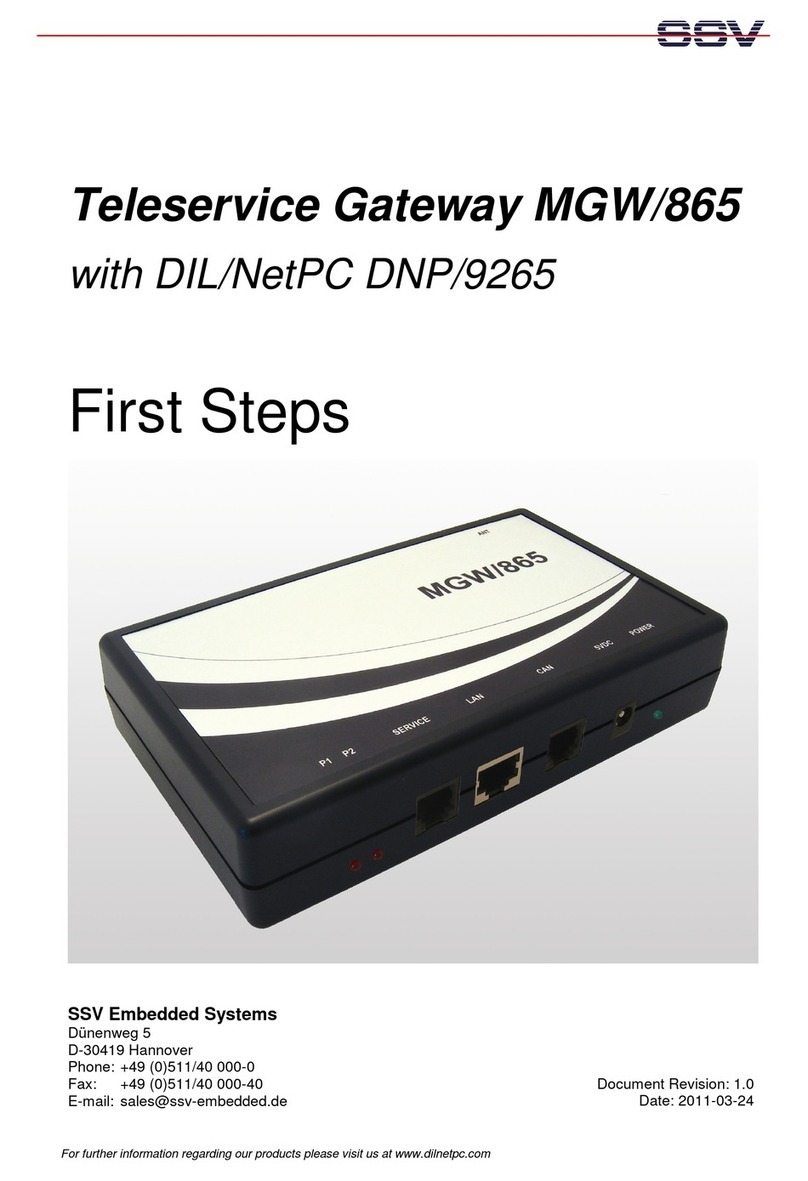
SSV MGW/865 User manual

SSV
SSV IGW/941 Application guide
SSV
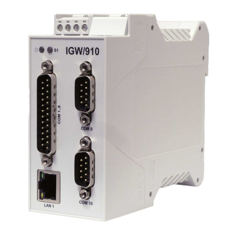
SSV IGW/910 Application guide
SSV
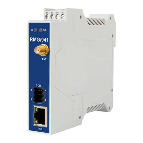
SSV RMG/941L User manual
Popular Gateway manuals by other brands
ZyXEL Communications
ZyXEL Communications VMG1312-B10B Series user guide
Epygi
Epygi QUADRO T1 Administrator's guide

ZyXEL Communications
ZyXEL Communications ZyXEL ZyWALL 10W user guide
Huawei
Huawei eSpace EGW1500E quick start

Eaton
Eaton Power Xpert Meter 2000 quick start guide
Polycom
Polycom DOC2237A Hardware installation guide
