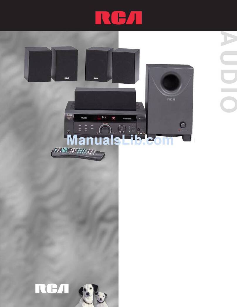
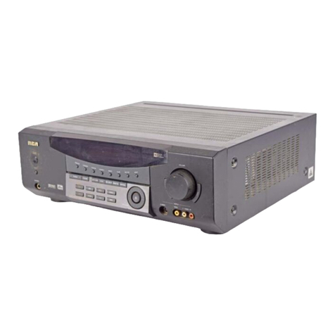
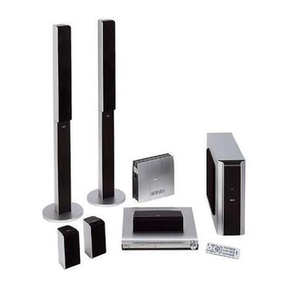
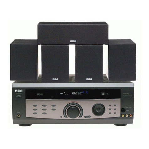
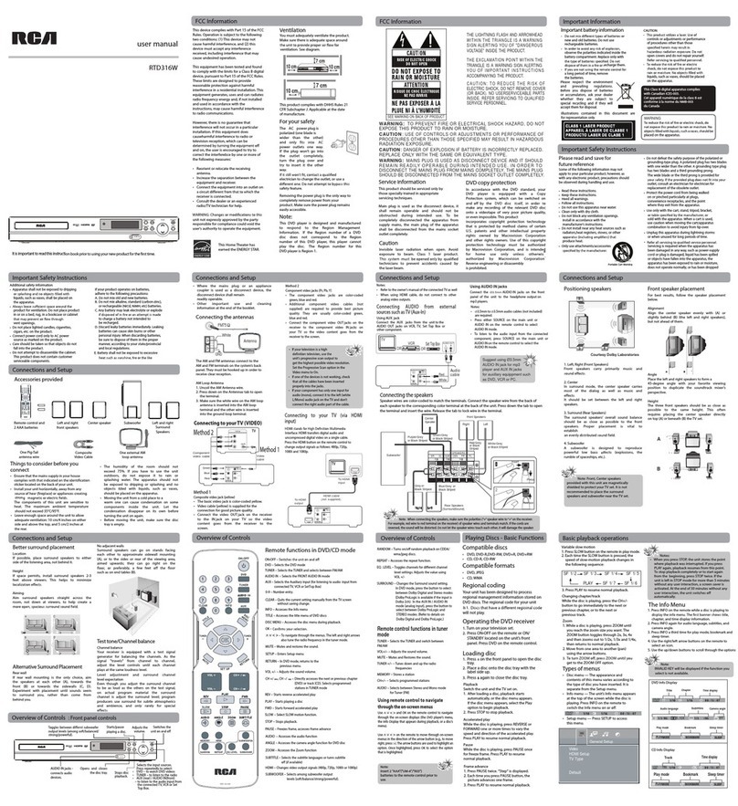
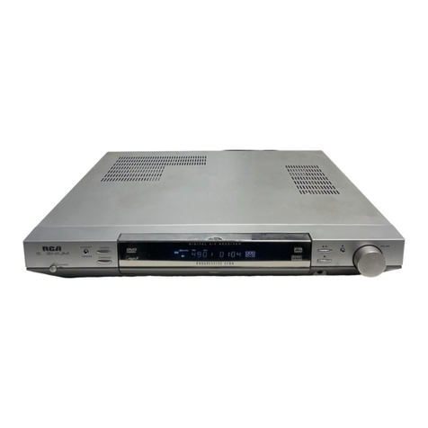
RCA Scenium RT2660R User manual

nCJll sc--__ NILJM
It is _mportant[o read [his qnstruc[ion book prior [o using your new product for the first [_me
Es qrnportanteleer este manual antes de usar pot vez pnmera su eu_po
I
i

This device complies with Part 15 of the FCCRules.
Operation issubject to the following two condi-
tions: (1) This device may not cause harmful
interference, and (2) this device must accept any
interference received, including interference that
may cause undesired operation.
In accordance with FCCrequirements, changes or
modifications not expressly approved by Thomson
multimedia inc. could void the user's authority to
operate this product.
This device generates and uses radio frequency (RF)
energy, and if not installed and used properly, this
equipment may cause interference to radio and
television reception.
If this equipment does cause interference to radio
or television reception (which you can determine by
unplugging the unit), try to correct the interference
by one or more of the following measures:
•Re-orient the receiving antenna (that is, the
antenna for the radio or television that is
"receiving" the interference).
•Move the unit away from the equipment that is
receiving interference.
•Plug the unit into a different wall outlet so that
the unit and the equipment receiving interference
are on different branch circuits.
If these measures do not eliminate the interference,
please consult your dealer or an experienced
radio/television technician for additional
suggestions. Also, the Federal Communications
Commission has prepared a helpful booklet, "How
To Identify and Resolve Radio TV interference
Problems." This booklet isavailable from the U.S.
Government Printing Office, Washington, DC 20402.
Please specify stock number 004-000-00345-4 when
ordering copies.
This product complies with DHHS Rules 21 CFR
Subchapter J. Applicable at the date of
manufacture.
ForYourSafety
The AC power plug is polar-
ized (one blade is wider than
the other) and only fits into
AC power outlets one way. If
the plug won't go into the
outlet completely, turn the
plug over and try to insert it
the other way. If it still won't
fit, contact a qualified electri-
clan to change the outlet, or use a different one.
Do not attempt to bypass this safety feature.
CAUTION: TO PREVENT ELECTRIC SHOCK,
MATCH WIDE BLADE OF PLUG TO WIDE SLOT,
FULLY INSERT.
ForYourRecords
In the event that service should be required, you
may need both the model number and the serial
number. In the space below, record the date and
place of purchase, and the serial number:
Model No.
Remote Control No.
Date of Purchase
Place of Purchase
Serial No.
ServiceInformation
This product should be serviced only by those spe-
cially trained in appropriate servicing techniques.
For instructions on how to obtain service, refer to
the warranty included in this Guide
TechnicalSpecification
Product:Dolby Digital Audio video receiver
Brand: RCA
Model: RT2660R
Electricalcurrentconsumption
Power Supply: 120V ~ 60Hz
Power consumption: 290 Watts
iMPORTER
Comercializadora Thomson de Mexico, S.A. de C.V.
Miguel de Cervantes Saavedra No. 57
Col. Ampliaci6n Granada
C.R 11529 Mexico D.R
Telefono: (55)25 81 53 20
RFC:CTM-980723.-KS5
A
THE LIGHTNING
FLASH AND ARROW-
HEAD WITHIN THE
TRIANGLE IS A
WARRING SIGN
ALERTING YOU OF
_RANGEROUS
VOLTAGE" INSIRE
THE PRODUCT,
CAUTION: TO REDUCE THE
RISK OF ELECTRIC SHOCK,
DO NOT REMOVE COVER
(OR DAGK), NO USER.
SERVICEABLE PARTS IN*
SIRE. REFER SERVICIN_
TO QUALIFIED SERVICE
PERSONNEL.
THE EXCLAMATION
POINT WITHIN THE
TRIANGLE IS A
WARNING SIGN
ALERTINGYOU OF
IMPORTANT
INSTRUCTIONS
ACCOMPANYING
THE PRODUCT.
SEEMARKING ON BOTTOM /BACK OF PRODUCT
WARNING: TO PREVENT FIRE OR ELECTRICAL
SHOCK HAZARD, DO NOT EXPOSETHIS PRODUCT
TO RAIN OR MOISTURE.
FCC Information
Getting Started
Unpacking the Receiver ............. 2
Inserting Batteries into Remote Control .3
Set Up and Maintenance of the
Receiver .......................... 3
Protect your Components from
Overheating ....................... 3
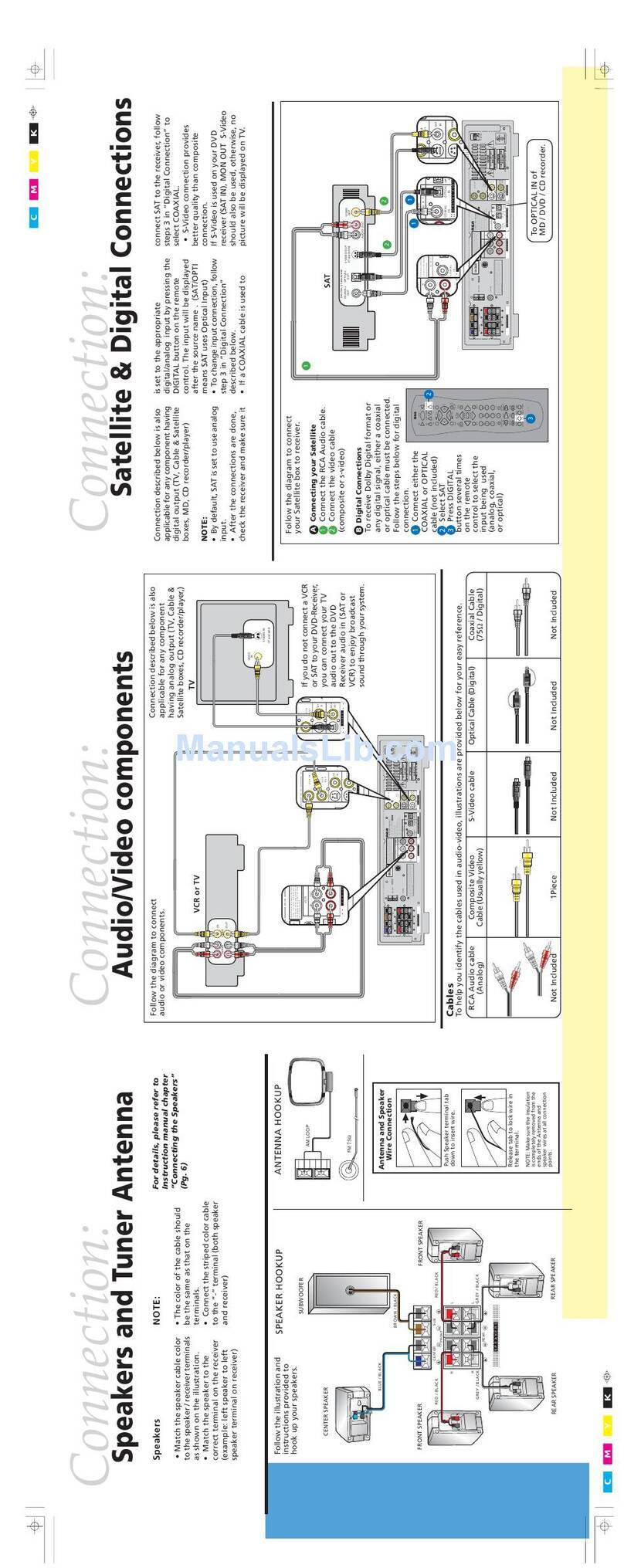
Connecting to Audio-Visual
Components ...................... 4
Digital Connection ................. 5
Component Connections ............. 5
Connecting Antennas ............... 5
Connecting the Speakers ............. 6
Connecting the Subwoofer ........... 6
Positioning your Speaker ............. 7
Front Speaker Placement ............. 7
Preferred Surround Placement ........ 8
Advanced Surround Setting .......... 8
Test Tone /Channel Balance .......... 9
Connecting for Power ............... 9
Using Headphones .................. 9
Factory Setting ..................... 9
Ooeratina your Receiver
Receiver Controls .................. 10
Your Remote Control ............... 11
Display .......................... 12
Switching OnlOff .................. 13
Show and Hide Control Panel ........ 13
Selection of AudiolVideo Source ...... 13
Using the Remote to Control Additional
Components ...................... 14
Using the receiver to play a Source .... 15
Operating the Radio ............... 16
Advanced Sound Control
Sound Enhancement Systems ........ 19
Fine Setting of Components ......... 21
Speaker Configurations ............. 22
Fine Setting of the Speakers ......... 24
Troubleshooting Tips
Troubleshooting Tips ............... 25
Receiver/Tuner Operation .......... 25
Remote Control Operation ......... 25
General ........................ 25
Cleaning the Exterior ............. 25
Equipment Specifications .......... 25
Care and Maintenance 26
Remote Codes ............... 27
Cable Codes ...................... 27
VCR Codes ....................... 27
TV Codes ........................ 28
Satellite Receivers ................. 29
Audio (RCA only) .................. 29
Laser disc Players .................. 29
Limited Warranty (U.S.) ........ 30
Limited Warranty (Canada) ..... 31

One receiver unit
One external FM Dipole
Antenna One external AM
loop antenna
-0
(+ -7
One pair of "AA"
batteries
one video cable
(single wire) with yellow
RCA connectors; (3000
3¸¸:}¸¸
_i'i}!iiiii!
i{{iiiii
{_iii_!ii!i
one audio cable
: one instruction book; (two wires) with red and
onesafetyleaflet;
• one Quick Connection Guide white RCA connectors;
OneThomson
UniversalRemote
Control

Inserting Batteries into Remote Control
insert two AA(R6) batteries according to the +and -
signs on the battery compartment. To use the remote
control, point it directly at your receiver. Whenever a
button is pressed, a red indicator will light up on the
remote control.
install batteries as follows:
1. Remove battery compartment door by applying
thumb pressure on battery door and then lift the
door out and off the cabinet.
2. insert 2 AA batteries in the compartment and
replace the compartment door.
Set up and Maintenance of the Receiver
,/_ IMPORTANTNOTE
•Provide spaces for sufficient ventilation as indicated
below. If the space is insufficient, the unit may over-
heat resulting in malfunction and shorter life time.
I10 cmi4"
o= .....
10 cnd4"
_l IlJflflll IlflllJfl Ilflfllll Iflflllll llllfllJl |


Digital Connections
Read instructions carefully when connecting compo-
nents to the receiver.
Digital in Jacks can accept Dolby Digital (AC-3), DTS
or PCM signals when compatible components are
connected.
Component Connections
ComponentVideo In & Out
The Component Video input is linked to DVD and SAT
modes. Selecting DVD or SAT mode will route a
component video signal connected to the Component
Video IN sockets to the Component Video Out sock-
ets. Using dedicated high-quality video cable (not
provided), connect the input from a device equipped
with Component Video output such as a DVD player.
Connect the Component Video output to a display
device (TV, monitor) to the Monitor outputs.

Connecting the Speakers
To connect the speakers, rotate the speaker jack
counter-clockwise. Insert the speaker wire into the
terminal. Secure the wire in place by turning the
speaker jack clockwise.
Speaker Polarity
When connecting the speakers, make sure the polari-
ties ("+" speaker wire to "+" on the receiver) of
speaker wires and terminals are matched. If the wires
are reversed, the sound will be distorted and will lack
bass ("out of phase" effect).
Connecting the Subwoofer
Adding aSubwoofer will increase bass response.
Connect the subwoofer wire to the SUB OUT jack on
the back of the unit.
This receiver offers ahigh flexibility for user to use a
large variety of speakers and subwoofers. For more
information please refer to section "Fine Setting of
the Speakers" in "Advanced Sound Control" on page
24.

Positioning your speaker
(_ Left, Right (Front Speakers)
They carry primarily music and sound effects
(_ Center
In surround mode, the center speaker carries much of
the dialogue as well as music and effects, it should be
set between the left and right speakers.
(_ Surround (Rear Speakers)
Their overall sound balance should be as close as pos-
sible to the front speakers. Proper placement is vital
to establish an evenly distributed sound field.
Subwoofer
A subwoofer isdesigned to reproduce powerful low
bass effects (explosions, the rumble of spaceships,
etc.) which dramatically heightens involvement with
the action on the screen. It istherefore recommend-
ed to connect subwoofers when small speakers are
used.
Magnetic shielding
Speakers placed lessthan two feet from the TV set
must be magnetically shielded in order to prevent
picture distortion.
It is not recommended to place the rear speakers
near the TV set.
Courtesy Dolby Laboratories
Front Speaker Placement
Even if you can't duplicate this ideal home theater
setup exactly, the suggestions for speaker placement
that follow will help you get good results.

Advanced Setting
Alternative Surround Placement
Rear wall
if rear wall mounting isthe only choice, aim the
speakers at each other (A), towards the front (B) or
even towards the sidewalls (C, D). Experiment with
placement until surround sounds seem to envelop
you, rather than coming from behind you.
Courtesy Do,by Laboratories
No adjacent walls
Surrounds can go on stands facing each other to
approximate the preferred sidewall mounting (A), or
to the sides or rear of the viewing area aimed
upwards. In the latter case, they can go right on the
floor, or preferably, a few feet off the floor such as
on end tables (B).
Courtesy Dolby Laboratories

Test Tone /Channel balance
Channel balance
Your receiver is equipped with a test signal generator
for balancing the channels. As the signal "travels"
from channel to channel, adjust the level controls
until each channel plays at the same loudness level.
Courtesy Dolby Laboratories
Level adjustment & surround channel level
expectation
Even though you adjust the surround channel to be
as loud as the others on the test signal, you'll find
that on actual program material the surround chan-
nel is usually much lower than the front. Don't be
tempted to readjust the surround level; program pro-
ducers use surround mostly for subtle atmospheric
and ambience, and only rarely for special effects. A
good surround mix doesn't call attention to itself; if
it did, it would soon become distracting.
Dolby Digital Manufactured
under license from Dolby
Laboratories. "Dolby', "Pro
Logic U" and the double-D
symbol are trademarks of Dolby Laboratories.
Copyright 1992-1997 Dolby Laboratories, Inc. All
Rights Reserved.
D I G ITA L Manufactured under License from
Digital Theater Systems, Inc. US Pat.
No. 5,451,942 and other world wide
SURROUND patents issued and pending. "DTS
Digital Surround", are trademarks of Digital
Theater Systems, Inc. copyright 1996 Digital
Theater Systems, Inc. All Rights Reserved.

[][]
II
vAux
I
• Press OK when DIMMER is displayed when scrolllng the Setup
menu to set dlsplay brightness. Use the arrow keys to select
among 4 dimmer levels. Press ok to confirm your setting.
9. TUNING
Press for about 2 seconds to search prevlous /next station in
descendlng /ascendlng frequency direction.
_n Preset mode, press to revlew all preset stations.
_nTuner mode, press to increase/decrease tuner frequencies.
10. SURR. MODE
This button selects DOLBY SURROUND modes (i.e. PLll MOVIE,
PLII MUSIC, Pro Logic) for Do[by Diglta[ 2CH /PCM stereo /
Analog inputs. With 5.1 DoIby Digital or DTS inputs, this but-
ton toggles output between 2 *channel down-mlx mode and
5.1 mode respectively. This button does not response with
other audio input configurations other than the ones men-
tioned above. Press repeatedly to select the surround mode
you want. ( refer to "Advanced Sound Control" on page 21)
lt. MEMORY
Pressto toggle between manual tuning mode and preset sta-
tion mode, Pressand hold to manually store tuner stationin
preset mode. (Referto pg 17 for details)
12. FM/AM
• Pressing the FM/AM button directly changes the active AVR
mode to tuner mode.
• Press to choose between FM/AM in TUNER mode.
• Holding this button continuously starts auto preset station
programming that tunes from FM to the lowest frequency
radio band and stores any tuned frequencies to the preset sta-
tion location until elther all radio bands are scanned or all pre-
set station locations are stored.
13. TEST TONE
When pressing it briefly, a short noise (test tone) will be gener*
ated in the speakers one by one so that you can adjust the vol-
ume of indlvldual speaker. (See page 24 for details)
14. EQ
• With down-m_xed 2 CH /PCM stereo /Analog inputs and 2
channels output only, this button allows the selection of differ-
ent equalizer to be applied to the audio output.
• Press repeatedly to select the desirable EQ mode (music style)
-FLAT, ROCK, POP, JAZZ, CLASSIC, VOCAL. Your choice will be
saved automatlcaliy.(Oniy available in Stereo mode)
15. DIGITAL INPUT/ ST /M
Press repeatedly to select the input device (analog /optlcaI /
optlca[ 2 /optlca[ 3 /coaxial), in FM mode, press to toggle
between stereo and mono.
16. V-AUX Input and S-VIDEO
For convenient use of your dlgltaI camera, family game
machines, second VCR, etc.
17. OPEN/CLOSE
Shows and hides the control panel when the unit is powered
on.

Your Remote Control
Please be sure you have inserted the batteries into the
remote control (see relevant section on page 3.) You can
test it by pressing any button. If it works, the red LED
will light.
1. ON/OFF

COAX
•Coaxial digital input selected.
STEREO
• Tuner stereo signal detected.
TUNED
• Tuner station detected.
SLEEP
•Unit in Sleep mode.
EQ
•EQ effect activated.
KHz /MHz
• Tuner frequency unit.
• Speakerlcons.

Switching on/off
•To enter Standby Mode, press the ON/STANDBY
button once.
• To power on the unit from Standby Mode, press
SOURCE _= or _ button on the main unit or
one of the source buttons on the remote control.
• To switch off the unit completely, press the
ON/STANDBY button or unplug the power cord from
the socket.
Show and Hide Control Panel
When the unit is powered on, touch the OPEN/ClOSE
button on the front panel of the unit to show the
control panel. Press again to hide the control panel.

Using the Remote to Control Additional
Components
You can set your remote to control other components
(like CD, TV, DVD, TAPE, etc.). What you need is to
encode them in advance (not necessary for recent
RCA & Proscan models).
1. Turn on the component to be programmed.
2. Look up the brand and corresponding code num-
ber in the code list from page 27 to 29.
3. Press and hold the corresponding Source Button
(like VCR, 113/,DVD) on the remote while entering
the code from the code list using the Number
Buttons.
4. Release the compo-
nent button, then press
ON,OFF to see if the
component will turn off.
5. If this does not work, repeat steps 3 and 4 by try-
ing to use the next code (if available) listed for the
brand of your component until the component
responds to the remote command.


5-Tune the stations by pressing TUNING UP or
DOWN on the main unit or REVERSE or FORWARD
on the remote control repeatedly until the desired
station isfound.
Alternatively, you can press and hold the respective
buttons for about one second to activate the
automatic SEARCH function, in this mode the receiver
will automatically tune frequencies until it finds a
station
Select sound effect if needed by pressing Preset EQ or
DSP sound (see "Advance sound section" for details).
Selecting Mono or Stereo Sound
Press ST/M on the main unit or the DIGITAL button
on the remote control to toggle between mono and
stereo sound in FM tuner mode (when available).

Storing radio stations:
The receiver can store up to 40 radio stations in
memory. You can enter every single radio station
yourself or the receiver can store all available radio
station automatically in an ascending order.
Automatic preset storing
1. Select the band by pressing FM/AM on the main
unit or AMeFM on the remote control.
2- Press and hold
FM/AM on the main
unit for 3 seconds.
"MEMORY" will be dis-
played in red and wiU
blink during the auto-
matic storing process.
Radio frequencies wiU be scanned and radio station
stored automatically. When all available radio
stations are stored or if all 40 memory locations are
full, the auto preset will stop.

6 Channelexternalinput
An external decoder (Dts, Dolby Digital, etc...) or a
device with built-in multi-channel decoder and 6
channel output connector (DVD player, TV...) can be
connected to the 6CH input. It istherefore possible
to play any future 6 Channels coding (For example,
SACD, DVD Audio) thanks to this connection. The
external decoder device will send the separated
audio information to the receiver that will then
amplify the signal and send to appropriate speakers.
To activate 6 Channel external input, press the
SOURCE _or _ on the receiver until 6 CH is
selected or press DVDe6CH twice on the remote
control.
Table of contents
Other RCA Receiver manuals

RCA
RCA Professional series User manual

RCA
RCA RT2500 - Dolby Digital Home Theater System Assembly instructions

RCA
RCA DRD420RE User manual

RCA
RCA RW2110 User manual

RCA
RCA RTD160 User manual

RCA
RCA DRD502RB User manual

RCA
RCA RT2280 User manual

RCA
RCA DRD202RA User manual

RCA
RCA DRD486RH User manual

RCA
RCA DRD455RH User manual

RCA
RCA RTD130 Instruction Manual

RCA
RCA RW2110 User manual

RCA
RCA DRD303RA User manual

RCA
RCA NRD313NA User manual

RCA
RCA Audio/Video Receiver User manual

RCA
RCA HD Receiver User manual

RCA
RCA RV-9968 User manual

RCA
RCA RT2500 - Dolby Digital Home Theater System User manual

RCA
RCA Scenium RT2660 User manual

RCA
RCA DRD302RA User manual