Operation and Use
When the ignition is switched on, the oil pressure indicator will illuminate along with the engine fault indicator
and the audible alarm will sound. Once the engine has started and gained sufficient oil pressure, all alarms
will stop. The unit is now monitoring the engine. Once a fault has been detected, the engine fault indicator will
flash for ten seconds, along with the indicator of the particular circuit that has caused the fault and the audible
alarm will sound.
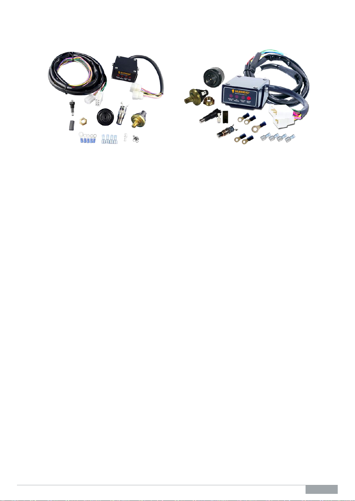
The Muirhead®Light Vehicle/Forklift Engine Protection system has been designed as a generic engine
protection system incorporating three inputs (one designated as a special alternating current (ac) circuit for
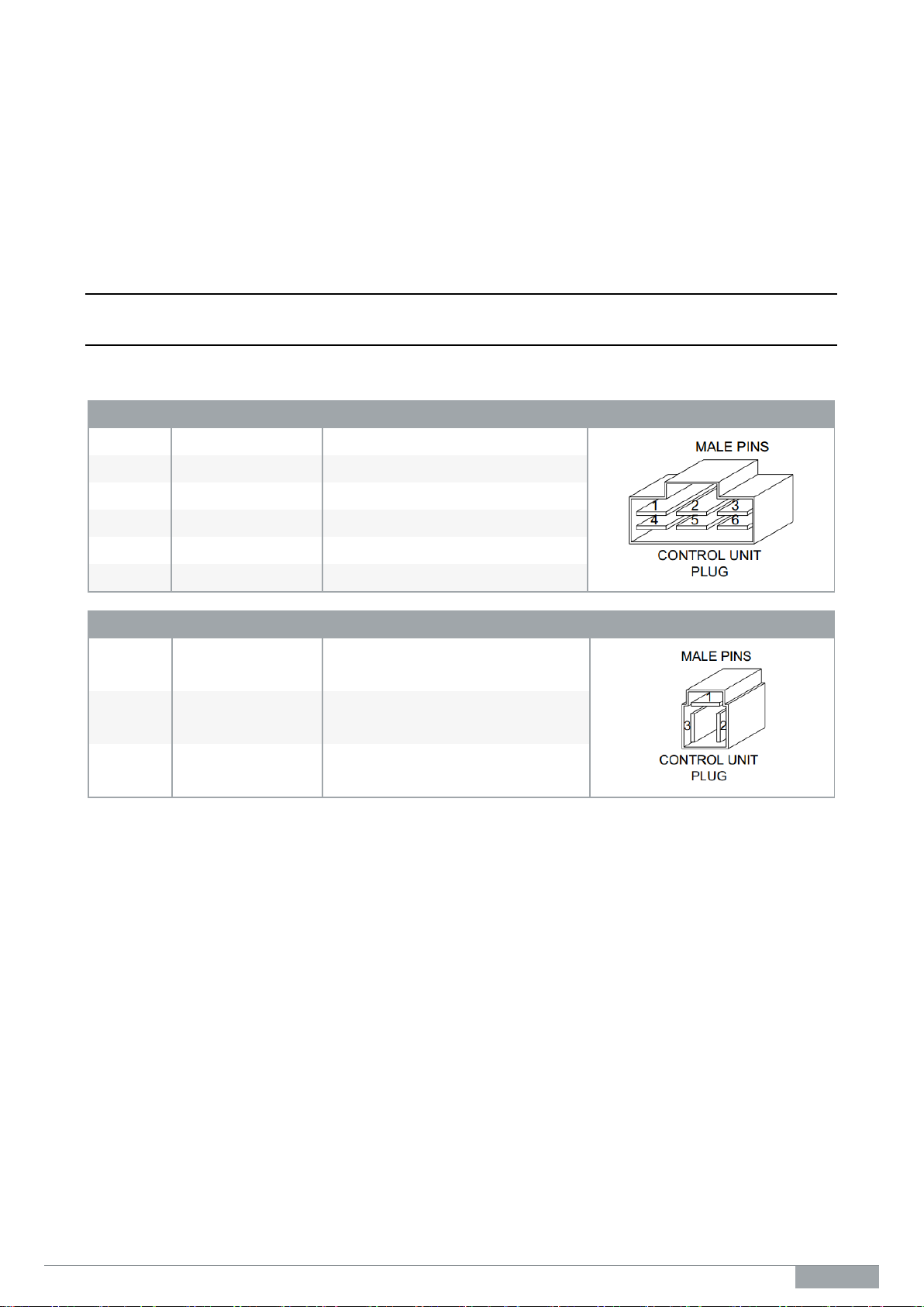
detecting coolant) and three outputs. The configuration of these inputs and outputs are as follows;
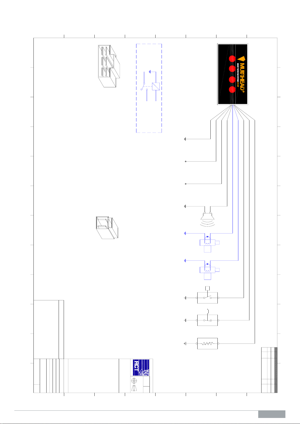
Engine Coolant Level
(White Wire)
This circuit detects low engine coolant. It is configured to have a five-second delay prior to activating its
individual warning indicator and the external audible alarm and optional shutdown process. This circuit
activates when the circuit becomes open.
Engine Temperature
(Yellow Wire)
This circuit detects high engine temperature. It is configured to have a one-second delay prior to activating its
corresponding warning indicator and the external audible alarm and optional shutdown process. This circuit
activates when the circuit becomes open.
Engine Oil Pressure Low
(Pink Wire)
This circuit detects low engine oil pressure. It is configured to have a one-second delay prior to activating its
corresponding warning indicator and the external audible alarm and optional shutdown process. This circuit
activates when the circuit becomes open.
Audible Alarm Output
(Green Wire)
The audible alarm output circuit switches on as soon as an individual warning indicator has been activated.
The alarm will remain on in a constant state until the operator has rectified the individual engine fault that was
registered on the control unit. Once the engine fault has been rectified, the fault indicator that was illuminated
on the control unit will cease along with the sounding of the alarm.
Idle Output (Optional) –Not Used
(Brown Wire)
This circuit operates as a direct opposite to the audible alarm circuit. It switches off when the audible alarm
switches on. This circuit is only used in conjunction with additional control systems that can return the engine
to idle on detection of a fault.
Shutdown ETR (Optional) –Not Used
(Yellow/Blue Wire)
This circuit operates similar to the idle output. However, this time delay is factory set to 10 seconds and
therefore allows the vehicle to run for 10 seconds after the detection of a fault and the warning system has
become active. The circuit is powered to run. The circuit switches off once a fault has been active for 10
seconds. This circuit also incorporates an override circuit to allow the vehicle to start when no oil pressure is
present.