RDI SPARTAN RAIL User manual

1
STAIR RAIL
Warning: Always wear safety goggles.
(Fig.4)
(Fig.3)
1¾"
1/8"
(Fig.1)
(Fig.2)
1.
Prepare all posts and mounting surfaces before installation.
2.
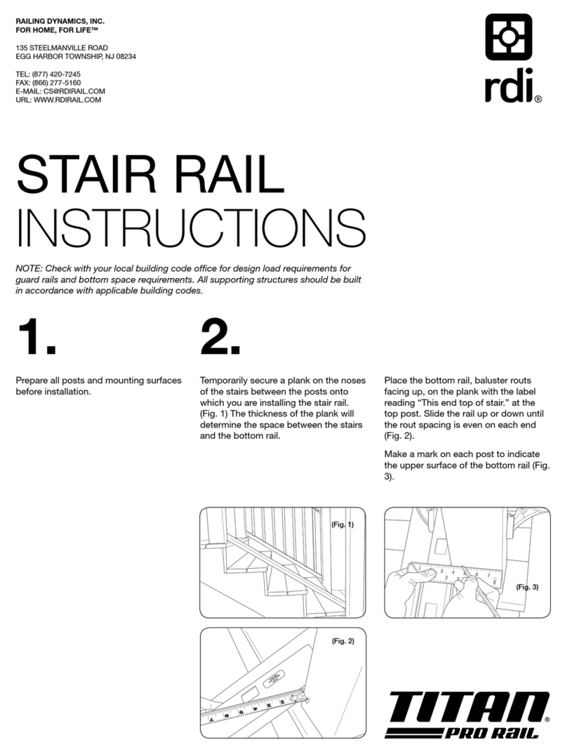
Temporarily secure a plank on the noses of the stairs between the posts onto which you are
installing the stair rail. (Fig. 1) The thickness of the plank will determine the space between the
stairs and the bottom rail.
Place the bottom rail, baluster holes facing up, on the plank and slide the rail up or down until
the baluster hole spacing is even on each end.
Tip: Clamp rail in place as shown in Fig. 2 to assist in assembly.
Measure the distance from post to the rst baluster hole and ensure spacing of at least 1¾" to
allow for bracket t (Fig. 3).
Trace the post onto the rail and mark 1/8" short at each end to allow for expansion (Fig. 4).
Cut the rail to t.
Tip: If using a power saw, a carbide tip blade of at least 60 teeth is recommended.
3.
Slide a bracket onto each end of the bottom rail (Fig. 5). Position the rail in place and slide the
brackets against the mounting surface. Check for proper t and attach to the post using the
mounting hardware.
Pre-drill using a 1/8"drill bit and install a supplied rail set screw through the side of each bracket
to secure the rail in place (Fig. 5). (Fig.5)
LIMITED WARRANTY
To obtain and review a copy of the warranty please go to: rdirail.com/warranty. You can also contact (877) 420-7245 or write to:
RDI Warranty, 545 Tilton Road, Egg Harbor City, NJ 08215 to obtain a copy of the warranty.

2
(Fig.10)
1"
(Fig.7)
(Fig.9)
STAIR RAIL CONTINUED
(Fig.8)
(Fig.6)
Baluster
tab
5.
Insert a baluster into each baluster hole of the bottom rail. Ensure the tab of each baluster
faces outward.
Set the top rail in place by inserting the rst baluster (at the upper post) into the corresponding
baluster hole of the top rail, and work toward the bottom (Fig. 9).
6.
Slide a bracket onto each end of the top rail and check for proper t. Pre-drill using a 1/8"drill
bit and secure bracket to the post using the supplied mounting hardware.
7.
Pre-drill through one side (the outside of the stair rail installation) of the top rail bracket using
5/32" drill bit at a location 1" from end of bracket as shown (Fig. 10).
Drive the top rail set screw through the bracket and rail to secure in place. Do NOT overtighten
screw or bracket may crack. Repeat for bracket on the other end of the rail.
8.
Complete your installation by installing your post cap onto your posts.
4.
Insert a baluster with tab facing the post into the rst and last baluster holes of the installed
bottom rail (Fig. 6).
Set the top rail in place by inserting these balusters into the corresponding holes in the top rail.
For ease of measurement, place the top rail to the side of the post or mounting surface as in
Figure 7. Adjust for plumb.
Trace the post or mounting surface onto each rail end and mark 1/8" short to allow for
expansion (Fig. 8). The rail can now be cut at these marks.

3
RAMPE D’ESCALIER
Avertissement: Toujours porter des lunettes de protection.
1.
Préparez tous les poteaux et les surfaces de montage avant l’installation.
2.
Fixez temporairement une planche sur les marches d’escalier entre les poteaux sur lesquels
vous installez la rampe. (Fig.1) L’épaisseur de la planche va déterminer l’espace entre les
marches et la lisse basse.
Placez la lisse basse, les trous de balustres dirigés vers le haut, sur la planche et faites-la glisser
vers le haut ou vers le bas jusqu’à ce que l’espacement des trous de balustre soit
le même à chaque extrémité.
Conseil: Maintenez-la lisse en place à l’aide d’un serre-joint comme le montre la gure2 pour
faciliter l’assemblage.
Mesurez la distance entre la lisse basse et le premier trou du balustre et assurez-vous qu’il y ait
un espacement d’au moins 1¾"(4,45cm) pour permettre un ajustement des supports d’attache
(Fig.3).
Tracez l’angle du poteau sur la lisse basse et marquez 1/8"(0,32cm) plus court à chaque
extrémité pour permettre de l’expansion des matériaux (Fig.4).
Coupez la lisse basse pour qu’elle corresponde au trait.
Conseil: Si vous utilisez une scie électrique, une lame d’au moins 60 dents à pointes au carbure
est recommandée.
(Fig.4)
(Fig.3)
1¾"
1/8"
(Fig.1)
(Fig.2)
(Fig.5)
3.
Faites glisser un support d’attache sur chaque extrémité de la lisse basse comme le montre la
gure 5. Mettez la lisse basse en place et glissez les supports d’attache contre la surface de
montage. Vériez qu’il y a un bon ajustement et attachez le support d’attache au poteau avec la
fournie à cet effet.
Pré percez en utilisant une mèche de 1/8"(0,32cm) et mettez une vis de réglage fournie dans le
côté de chaque support d’attache pour xer la lisse en place (Fig.5).
GARANTIE À VIE LIMITÉE
Pour plus de détails sur la garantie, visiter le: rdirail.com/warranty. Vous pouvez également téléphoner le (877) 420-7245 ou écrire à
RDI Warranty, 545 Tilton Road, Egg Harbor City, NJ 08215 pour obtenir une copie de la garantie.

4
RAMPE D’ESCALIER (SUITE)
Cran du
balustre
4.
Insérez un balustre avec le cran faisant face au poteau dans les trous du premier et du dernier
balustre de la lisse basse installée (Fig.6).
Réglez la main courante en place en insérant ces balustres dans les trous correspondants de
la main courante. Pour faciliter les mesures, placez la main courante à côté du poteau ou de la
surface de montage comme indiqué à la gure 7. Réglez l’aplomb.
Tracez l’angle du poteau ou la surface de montage sur chaque extrémité de la main
courante et marquez d’un trait de 1/8" (0,32cm) plus court à chaque extrémité pour permettre
l’expansion des matériaux (Fig.8). La main courante peut maintenant être coupée à ces
marques.
5.
Insérez un balustre dans chaque trou de balustre de la lisse basse. Assurez-vous que le cran
de chaque balustre est bien tourné vers l’extérieur.
Réglez la main courante en place en insérant le premier balustre (au poteau supérieur) dans le
trou de balustre correspondant de la main courante, et continuez ainsi vers le bas (Fig.9).
(Fig.14)(Fig.10)
1"1"
(Fig.7)
(Fig.9)
6.
Faites glisser un support d’attache sur chaque extrémité de la main courante et vérier qu’il
y a un bon ajustement. Pré percez en utilisant une mèche de 1/8"(0,32cm) et xez le support
d’attache au poteau avec la quincaillerie fournie.
7.
Pré percer les trous à travers un côté du support d’attache de la main courante (le côté
extérieur de l’installation) à l’aide d’une mèche de 5/32" (0,39cm) à un emplacement de 1"
(2,54cm) de l’extrémité du support d’attache comme illustrée (Fig.10).
Introduire la vis de réglage à travers le support d’attache et la main courante pour sécuriser en
place. NE PAS trop serrer la vis sinon le support d’attache pourrait se ssurer. Répéter pour le
support d’attache de l’autre extrémité de la main courante.
8.
Terminez votre installation en installant les capuchons de poteau.
(Fig.6)
(Fig.8)
34107776
REV. 05.17
Table of contents
Languages:
Other RDI Indoor Furnishing manuals
Popular Indoor Furnishing manuals by other brands

Safavieh Furniture
Safavieh Furniture Rodi BST3019A manual

raumplus
raumplus Apperia Planning, Assembly, Installation

New Classic Furniture
New Classic Furniture CELESTE T400-3P Assembly instruction

&Tradition
&Tradition Norm Architects Naervaer NA10 instructions

Whalen
Whalen Evans Creek CTCDC-1 manual

Next
Next 231989 Assembly instructions

swissflex
swissflex basic operating instructions

Article
Article ERNO Dining Table Assembly instructions

Habitat
Habitat KIRBY KIRB-CH-SS20-A Assembly instructions

ABACO MACHINES
ABACO MACHINES AWT7523C Operation manual

ErgoCentric
ErgoCentric upCentric 2L owner's manual

Night & Day Furniture
Night & Day Furniture Ginger Twin Loft Bunk Bed Assembly instructions