Create Room DREAMBOX User manual

oh happy day
YOU’VE RECEIVED THE DREAMBOX!
CUSTOMERSERVICE@CREATEROOM.COM
WWW.CREATEROOM.COM
USA / CANADA: 801-226-2686 (M-F 9AM-5PM MST)
UK/EU: +49 40 69632955 OR +44 7759 335868
It’s already time for your first project. Let’s get to work!
To make the process simple and easy to follow, we’ve broken down the DreamBox assembly
instructions into sections. The DreamBox pieces will come in 8 boxes. All of the hardware will
be found in a separate hardware box.
Our customer service team are the friendliest bunch of furniture experts. Do not hesitate to
reach out to them if you have questions at any point of the assembly process.
We are excited for you to enjoy your inspiring new workspace and can’t wait to see pictures!
Share your photos on Facebook and Instagram and don’t forget to tag @createroomco.
Happy crafting!
U102022
DreamBox Assembly Instructions - Boswell Build
(Proprietary patented product and instructions. Do not copy or distribute.)
Proprietary, patented product and assembly instructions. Do not copy or distribute.
Box 1 includes: Center Box Side 1 (CB1), Center Box Side 2 (CB2), Center Box Shelf 2
(CB Shelf 2), Center Box Shelf 1 (CB Shelf 1), (2) Center Box Divider (CB Divider),
Center Box Lid (CB Lid), Center Box Base (CB Base), Table 1
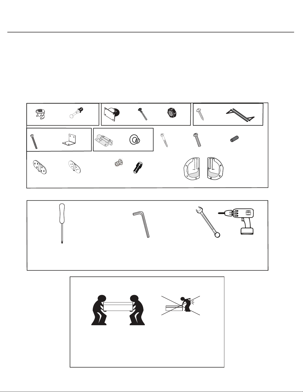
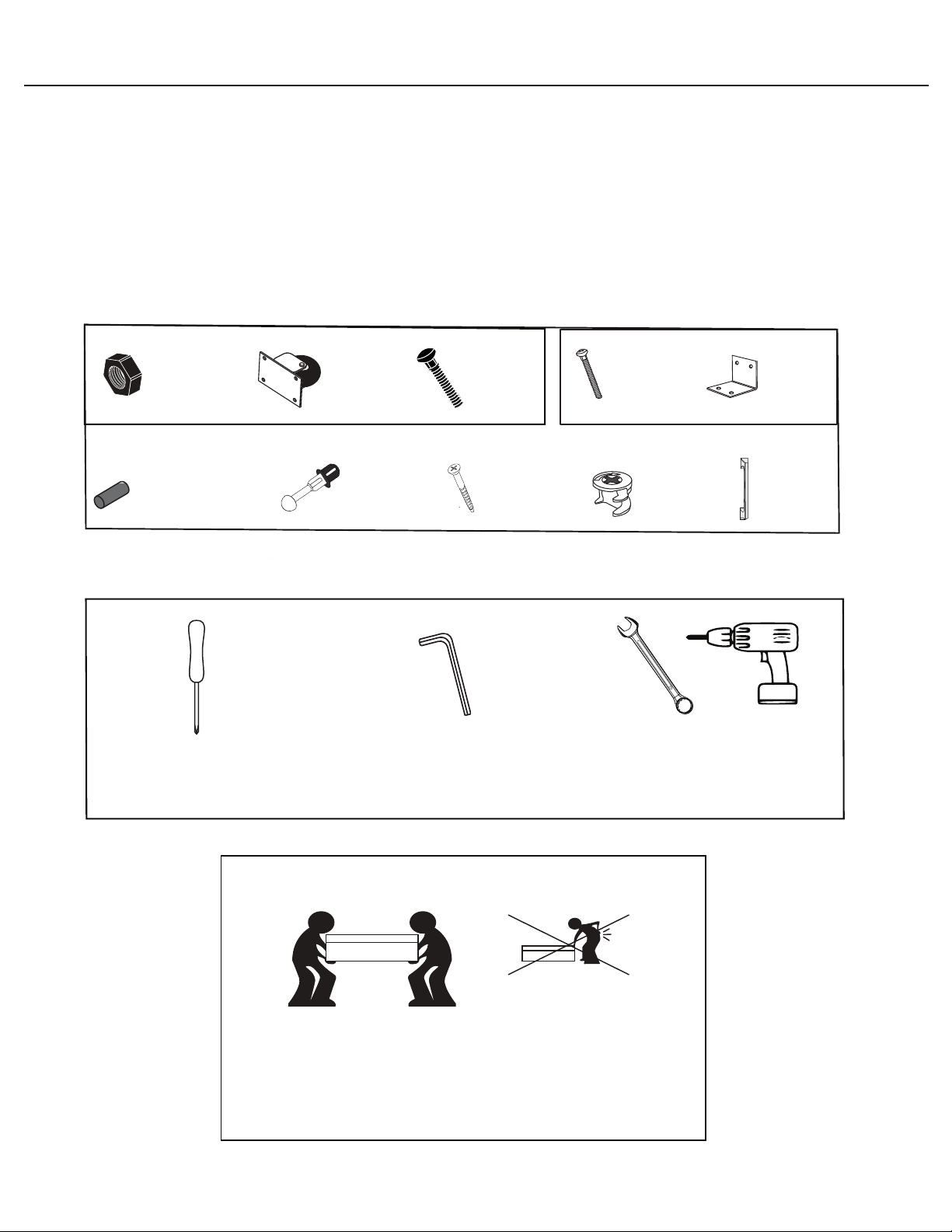
CENTER BOX (BOX 1 AND BOX 2)
Our furniture is
designed to be built
with two people.
Please do not try to
build alone.
A Friend
(not included)
Hardware you’ll need:
Tools you’ll need:
Phillips
Screw Driver
Electric Drill with
socket extensions
or 10mm wrench
Allen Wrench
(included)
x24
Locking
Cams
x24
Posts
x16
Wheel
Bolts
x16
Wheel
Nuts
x4
Caster
Wheels
F20
Box 2 includes: Center Box Upper Back (CB Upper Back), Center Box Lower Back
(CB Lower Back), Center Box Middle Back (CB Middle Back), Table 2
x1
Left Hand
Table Lift
x124
#1:13mm
Euro Screws LH
x1
Right Hand
Table Lift
RH
x23
#5: 28 mm
Panhead Screws
x15
Standard
Hinges
x3
Folding
Hinges
x8
Connecting
Bolts
x4
Base Support
Pins
x8
#3: 1 1/2”
Conrmat
Screws
x4
#4: Phillips
Screw
x2
Adjustable
Table Legs
x8
#8: Phillips
Screw
x2
Angle
Brackets
x2
Barrel
Locks
Plug
inserts
x2

3
Left Box
Facing Side 2
Divider
Use the shelf peg tool to install another (24)
in holes on Side 1 of Left Box Divider
to match peg placement from step 5.
x24
Shelf
Pegs Shelf Peg Tool
3
Left Box
Facing Side 2
Divider
Use the shelf peg tool to install another (24)
in holes on Side 1 of Left Box Divider
to match peg placement from step 5.
x24
Shelf
Pegs Shelf Peg Tool
1
Bottom View
Green dowel
Post hole
Pre-drilled
Wheel Bolt
holes
Post hole
CB Base
RH
1
*Do not overtighten nuts. (Wheels should
spin freely). Tighten until you can't loosen
with your hand (that's when you know it
is tight enough).
Insert (12) Posts into
corresponding Post holes
in CB 1,
(2) Base Support
Pins to corresponding
holes and (1) Plug Hole Cover.
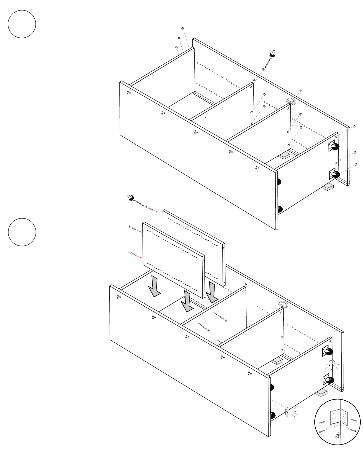
2
#1 Euro Screws (4)
Install (1) Left Hand Table lift using
(4) #1: 13 mm Euro Screws.
Center Box
Build on a blanket for best results
F20
CB1
Caster
Wheels (4)
Wheel Nuts (16)
Wheel
Bolts (16)
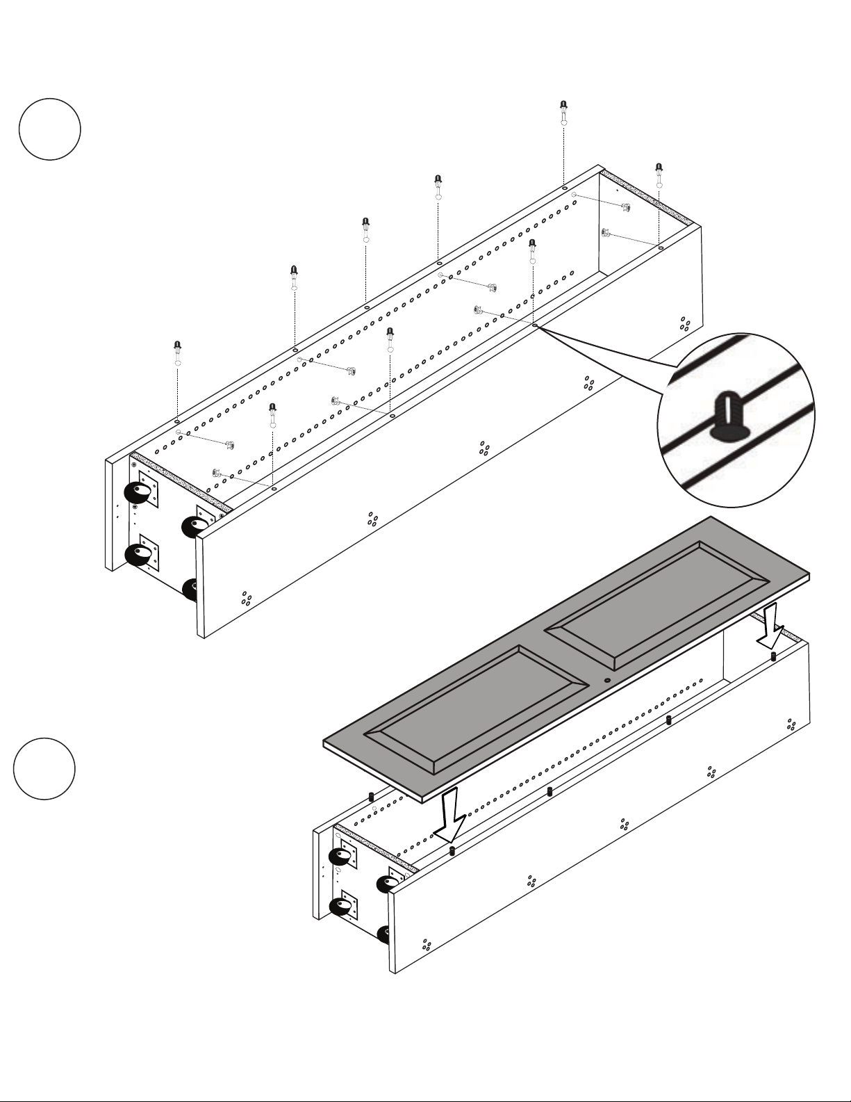
Locking
Cams (6)
Push (16) Wheel Bolts into top of CB base.
Install (4) Caster Wheels onto Wheel Bolts. Secure
with (16) Wheel Nuts using 10mm wrench
or drill with socket wrench extension.
Posts (12)
Base Support Pins (2)
Top View
CB Base
*Tip: Install Locking Cams with the arrow
pointing towards the edge of the wood.
Insert (6) Locking Cams into holes on CB Base.
Proprietary, patented product and assembly instructions. Do not copy or distribute.
Proprietary, patented product and assembly instructions. Do not copy or distribute.
Plug Hole
Cover (1)

Proprietary, patented product and assembly instructions. Do not copy or distribute. 2
CB Shelf 1
CB Shelf 2
CB Lid
3
Install Locking Cams with the arrow pointing towards
the edge of the wood.v
Insert (18 Locking Cams) into CB Shelf 1, CB Shelf 2,
CB Lid in the following oreintation.
Locking
Cams (6)
Locking
Cams (6)
Locking
Cams (6)

3
7
Proprietary, patented product and assembly instructions. Do not copy or distribute.
Proprietary, patented product and assembly instructions. Do not copy or distribute.
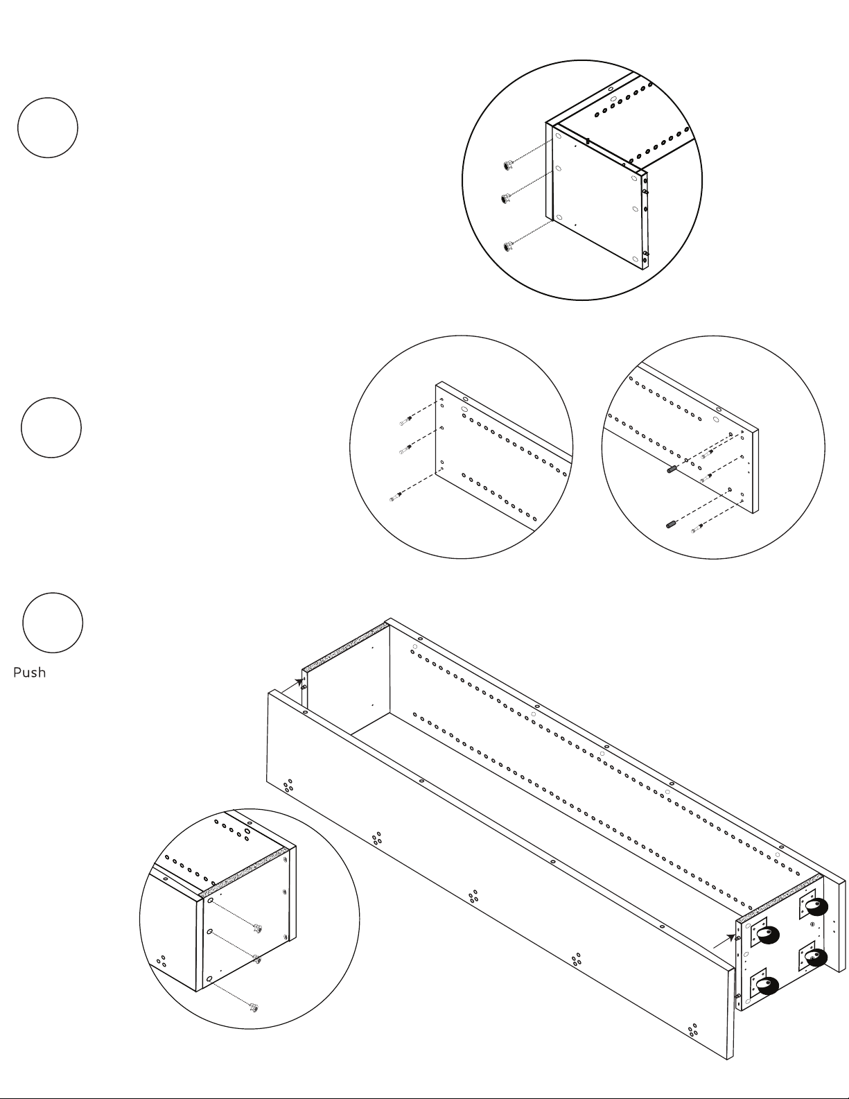
CB Shelf 1
5
CB Base
4Stand CB 1 on its edge, finished edge up. Be sure
posts, dowels & pins are aligned. Push CB 1
carefully into CB Base.
Use a shelf from your shelf bundle to support
attached side pieces.
Center Box
CB Base
CB 1
CB 1
F20
Lock cams in place by turning
220 degrees.
7
Proprietary, patented product and assembly instructions. Do not copy or distribute.

4
Proprietary, patented product and assembly instructions. Do not copy or distribute.
Carefully fit CB Lid & CB Shelf 2 to
CB Side 1. Be sure Posts are aligned
with holes. Tap edges until
secure.
6
Secure CB Shelf 2 & CB Lid to CB1 using (6)
Locking Cams. To lock cams, turn 220 degrees.
Use a shelf to support Lid and Shelf 2.
*Note that 3 Locking Cams will insert into the TOP
of Lid (outside of the box) and the other 3
will insert into the UNDERSIDE of Shelf 2.
7
**Finished edges facing up**
F20
CB Lid
CB1
CB Shelf 2
Locking
Cams (6)
CB Lid
CB1
CB Shelf 2
Slide CB dividers (2) in one at a time
& secure to CB Lid &
(4) #3 1 1/2 Confirmat Screws
in each divider.
Use ONLY a MANUAL phillips
screw driver.
Install (2) angle brackets
using (8) #5 14mm washer
screws.
11

5
Proprietary, patented product and assembly instructions. Do not copy or distribute.
Insert (12) Posts into
corresponding post holes
in CB 2 & (2) Base Support
Pins to corresponding
holes.
Install (1) Right Table Lift using
(4) #1: 13 mm Euro Screws
Stand CB 2 on its edge with back
groove at the bottom and be sure
posts, dowels & pins are aligned with
built section. CB 2 carefully
into built section.
8
9
RH
RH
CB Lid
CB Shelf 2
CB2
Posts (12)
#1 Screws (4)
Base Support
Pins (2)
CB2
Slide CB dividers (2) in one at a time
CB Lid &
CB Shelf 2
using
(4) #3 1 1/2 Confirmat Screws
Use ONLY a MANUAL phillips
(2) angle brackets
(8) #5 14mm washer
CB Divider
CB1
Slide CB dividers (2) in one at a time
& secure to CB Lid &
(4) #3 1 1/2 Confirmat Screws
11
Slide CB dividers (2) in one at a time
& secure to CB Lid &
(4) #3 1 1/2 Confirmat Screws
11
Slide CB dividers (2) in one at a time
& secure to CB Lid &
CB Shelf 2
(4) #3 1 1/2 Confirmat Screws
in each divider.
11
Plug Hole
Cover (1)
6
Proprietary, patented product and assembly instructions. Do not copy or distribute.
RH
Slide CB dividers (2) in one at a time
& secure to CB Lid &
CB Shelf 2
using
(4) #3: 1 1/2 Confirmat Screws
in each divider.
Use ONLY a MANUAL phillips
screw driver.
Install (2) Angle Brackets
using (8) #5: #8 Phillips
Screws.
11
RH
CB Shelf 2
CB Lid
CB1
CB Divider
CB1
*Tip: If you ordered the three
drawers, now is a good time
to assemble them. Use the
separate instruction sets.
Tighten (12) Locking Cams until secure.
*Note that 3 Locking Cams will insert into
the TOP of Lid (outside of the box).
Locking
Cams (12)
10
CB2
#3 Screws (4)
RH
Angle Bracket
#5 Screws (4)
Slide CB dividers (2) in one at a time
&
CB Shelf 2
using
(4) #3 1 1/2 Confirmat Screws
CB Shelf 2
CB Lid
CB1
CB Divider
Slide CB dividers (2) in one at a time
&
CB Shelf 2
using
(4) #3 1 1/2 Confirmat Screws
CB Shelf 2
CB Lid
CB1
CB Divider
Slide CB dividers (2) in one at a time
CB Shelf 2
using
(4) #3 1 1/2 Confirmat Screws
CB Shelf 2
CB Lid
CB1
CB Divider
7
Proprietary, patented product and assembly instructions. Do not copy or distribute.
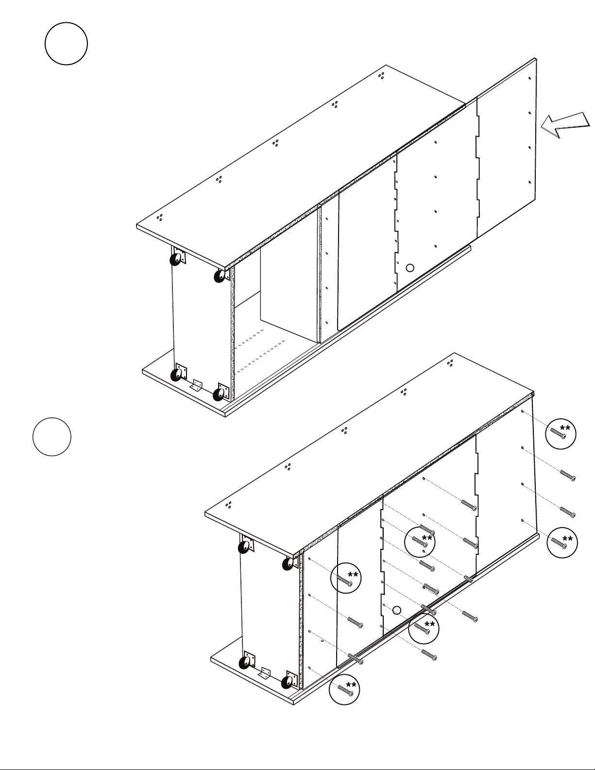
Side 2
Side 2
CB Lower Back CB Middle Back CB Upper Back
#5 Screws (19)
12
Carefully slide CB Back Panels into
back grooves one at a time, start-
ing with CB Lower Back. Be sure that
holes are aligned with
corresponding pilot holes.
13
Install (19) #5: 28 mm Panhead
Screws into corresponding holes
on back panel to secure. It is safe
to use an electric screwdriver
for this step.
*Make sure back fits
tightly and holes line up
with pilot holes in built
section.
3
Left Box
Facing Side 2
Divider
19
23
27
31
35
39
43
47
5
Use the shelf peg tool to install another (24)
shelf pegs in holes on Side 1 of Left Box Divider
to match peg placement from step 5.
x24
Shelf
Pegs Shelf Peg Tool
Proprietary, patented product and assembly instructions. Do not copy or distribute.
Screw in four corners of each
panel first.

8
Proprietary, patented product and assembly instructions. Do not copy or distribute.
16
Attach (2) Barrel Locks
(with
knob in down position) to Table
2 using (8) #1: 13mm Euro Screws.
17
Install (2) Adjustable Table Legs
using (8) # 4: Screws . Use
pre-drilled holes to guide you.
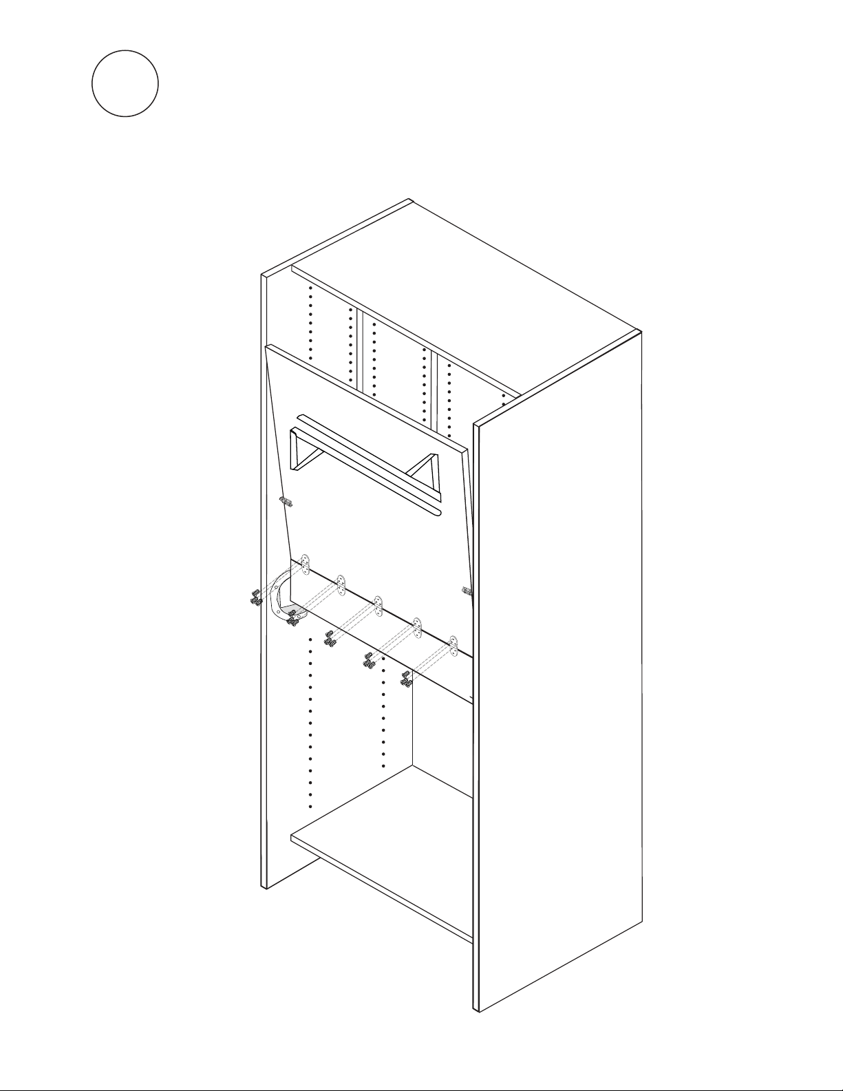
14
Install (3) Folding Hinges
with the barrel facing down to
Table 1 using (9) #1: 13mm Euro
Screws.
15
Turn Table 1 over and install (5)
Standard Hinges with the barrel
facing up to the other side using
(15) 1:13mm Euro Screws .
#
Table 1
Folding Hinges (3)
#1 Screws (9)
Table 1
Standard Hinges
#1 Screws (15)
Center Box
Table 2
#1 Screws (8)
#4 Screws (8)
7
Proprietary, patented product and assembly instructions. Do not copy or distribute.
This side up.
Caution: Do NOT over screw. Take your time!
IMPORTANT NOTE!
To collapse table legs, pull joint in towards the middle.
Refer to page 11 for any questions regarding the table legs.

9
Proprietary, patented product and assembly instructions. Do not copy or distribute.
LH
Slide Table 1 into Left and RightTable Lift slots as
shown, matching 3 barrel-down hinges up with
three hinge recesses on the top of CB Shelf 1..
18
Have one person pull Table 1 into the
down position and hold while the
other secures three recess hinges
using (9) #1: 13mm Euro Screws.
LH
LH
19
#1 Screws (9)
10
Proprietary, patented product and assembly instructions. Do not copy or distribute.
With Table 1 in the UP position, rest Table 2 on its edge, also in the
UP position with the hinges facing out. LOCK into place with Barrel
Locks. Attach (5) Standard Hinges to Table 2 with remaining
(15) #1:
13mm Euro Screws adding one screw at a time to each hinge in rotation.
20
HEAVY TABLE! THIS STEP REQUIRES TWO PEOPLE.
LH
#1 Screws (15)
*Table does not store up. Table in the up position is for accessing lower supplies under the table.

11
Proprietary, patented product and assembly instructions. Do not copy or distribute.
To access storage below the table, lift table &
lock in the “up” position.
IMPORTANT:
Table must be in “down” position before
closingthe DreamBox.
CAUTION! HEAVY TABLE
Use care when lifting table or changing heights.
Always lock table “UP” when adjusting legs.
IMPORTANT NOTE!
To collapse table legs, pull joint in
towards the middle and push
joint towards the table to lock.
TA BLE OPERATION:
Unlock
Lock
IMPORTANT NOTE!
When closed the hinge part comes
out about 30 degrees to lock.
Proprietary, patented product and assembly instructions. Do not copy or distribute.
Box 3: (1) Door, (1) Right/Left Box Divider (R/L Divider), Left Box Side 1
(LB1), Left Box Side 2 (LB2), Left Box Base (LB Base), Left Box Lid (LB Lid),
(1) Left Shelf (R/L Shelf).
LEFT AND RIGHT SIDE BOXES: BOX 3 & BOX 4
Our furniture is
designed to be built
with two people.
Please do not try to
build alone.
A Friend
(not included)
Hardware you’ll need:
Tools you’ll need:
Phillips
Screw Driver
Electric Drill with
socket extensions
or 10mm wrench
Allen Wrench
(included)
x42
Locking
Cams
x42
Posts
x32
Wheel
Bolts
x32
Wheel Nuts
x8
Base Support
Pins
x8
Wheel
Casters
F20
x16
#8: Phillipp
Washer Screws
x4
Angle
Brackets
x2
Door Handles
[Screws included]
x8
1 1/2”
Conrmat
Screws
Box 4: (1) Door, (1) Right/Left Box Divider (R/L Divider), Right Box Side 1
(RB1), Right Box Side 2 (RB2), Right Box Base (RB Base), Right Box Lid (RB Lid),
(1) Right Shelf (R/L Shelf).

12
LB Base
Wheel
Bolts (16)
Wheel
Nuts (16)
Left Side Box Shown.
Build on a blanket for best results
LB2
2
Green dowel
Post hole
Locking
Cam hole
Unnished edge
Pre-drilled
Wheel Bolt
holes
Pre-drilled
angle bracket
holes
Divider
screw
hole
Install (2) Base Support Pins and (3) Posts
into bottom end of Side 2 as shown. Install
another (3) Posts into top end of Side 2.
3
LB2
TOP
BOTTOM
Proprietary, patented product and assembly instructions. Do not copy or distribute.
Locking
Cams (6)
1
*Do not overtighten screws (wheels should spin freely)
Posts (3)
Base Support
Pins (2)
With finished edges of LB base
and LB lid facing down, match
up posts with post holes in
LB Side 2. Push base and lid into
Side 2.
Push (16) Wheel Bolts into the top
of the base. Install (4) Caster Wheels
onto bolts. Secure with (16) Wheel Nuts
using 10mm wrench or drill with
socket wrench extension.
Insert (6) Locking Cams in holes on box.
LB Base
LB Lid

13
Left Side Box Shown.
Insert (3) Locking Cams
*Note that Locking Cams will
insert on the outside of the
box
4
LB1
LID
into the top side of the lid.
Turn cams 220 degrees
with phillips screwdriver
until locked in place.
Proprietary, patented product and assembly instructions. Do not copy or distribute.
5
Install (2) Base Support Pins and (3) Posts
into bottom end of Side 1 as shown. Install
another (3) Posts into top end of LB1.
6
LB1 into the post holes on
base and lid. Tighten with phillips
screwdriver until secure (about 220
degrees).
*Note that again all Locking Cams will
insert on the outside of the box.
BOTTOM
TOP
LID
Locking
Cams (3)
Posts (3)
Base Support
Pins (2)
LB Lid
Posts (3)
Locking
Cams (3)
14
Be certain each post is secure.
Next, carefully turn box over so that DOOR is facing down.
Be sure that door does not slide off posts.
Left Side Box Shown.
Build on a blanket for best results
1
Left Box
3
To secure door. insert (9) cams
both sides of the interior of the box and
turn with an Allen Wrench until locked in
place.
x9
Locking
Cams
4
Insert (24) shelf pegs into holes in Side 2
using the Shelf Peg Tool. We recommend
placing pegs as shown. *Be sure pegs are
secure in their holes
x24
Shelf
Pegs
Fit shelf peg tool
over shelf peg
Press peg firmly until
in snaps into place
Pull shelf peg tool
down and off
LB1
Left Box
3
To secure door. insert (9) cams
both sides of the interior of the box and
turn with an Allen Wrench until locked in
place.
x9
Locking
Cams
4
Insert (24) shelf pegs into holes in Side 2
using the Shelf Peg Tool. We recommend
placing pegs as shown. *Be sure pegs are
secure in their holes
x24
Shelf
Pegs
Fit shelf peg tool
over shelf peg
Press peg firmly until
in snaps into place
Pull shelf peg tool
down and off
7Insert (9) Posts HEAD DOWN into
post holes on the edges of LB1 & LB2.
To secure door, insert (9) Locking Cams along
both sides of the interior of the box and
turn with a Phillips Screwdriver until locked
in place. (About 220 degrees).
8Carefully set Door over 9 posts
making sure posts align with post
holes in Door.
DO NOT force Door onto posts.
LB1
Posts (9)
Locking
Cams (9)
Slide CB dividers (2) in one at a time
& secure to CB Lid &
CB Shelf 2
(4) #3 1 1/2 Confirmat Screws
in each divider.
Use ONLY a MANUAL phillips
screw driver.
Install (2) angle brackets
using (8) #5 14mm washer
screws.
11
Slide CB dividers (2) in one at a time
& secure to CB Lid &
CB Shelf 2
using
(4) #3 1 1/2 Confirmat Screws
in each divider.
Use ONLY a MANUAL phillips
screw driver.
Install (2) angle brackets
using (8) #5 14mm washer
screws.
11

3
15
7
8
Left Box
Side 1
Left Box
Side 1
Slide Divider in and align with
pilot holes on lid and base.
Use a Phillips screw driver to MANUALLY
install divider using (4) #3: 1 1/2” Confirmat
Screws into pilot holes to secure divider.
Divider MUST be installed manually to
avoid damaging your DreamBox.
Install (2) Angle Brackets at correspond-
ing pilot holes in base and sides using (8)
#5: 14mm Washer Screws.
6
Left Side Box Shown.
Next, you will install the Divider.
3
9
11
10
LB1
LB1
Divider
RH
#5: Screws (4)
RH
#5: Screws (4)

16
RB Base
Wheel
Bolts (16)
Wheel
Nuts (16)
Right Side Box Shown.
Build on a blanket for best results
RB2
2
Green dowel
Post hole
Locking
Cam hole
Unnished edge
Pre-drilled
Wheel Bolt
holes
Pre-drilled
angle bracket
holes
Divider
screw
hole
Install (2) Base Support Pins and (3) Posts
into bottom end of Side 2 as shown. Install
another (3) Posts into top end of Side 2.
3
TOP
BOTTOM
Proprietary, patented product and assembly instructions. Do not copy or distribute.
Locking
Cams (6)
1
*Do not overtighten screws (wheels should spin freely)
Posts (3)
Base Support
Pins (2)
With finished edges of RB base
and RB lid facing down, match
up posts with post holes in
RB Side 2. Push base and lid into
Side 2.
Push (16) Wheel Bolts into the top
of the base. Install (4) Caster Wheels
onto bolts. Secure with (16) Wheel Nuts
using 10mm wrench or drill with
socket wrench extension.
Insert (6) Locking Cams in holes on box.
RB Base
RB Lid
RB2
9
17
Insert (3) Locking Cams
*Note that Locking Cams will
insert on the outside of the
box
4
RB1
LID
into the top side of the lid.
Turn cams 220 degrees
with phillips screwdriver
until locked in place.
Proprietary, patented product and assembly instructions. Do not copy or distribute.
5
Install (2) Base Support Pins and (3) Posts
into bottom end of Side 1 as shown. Install
another (3) Posts into top end of RB1.
6
RB1 into the post holes on
base and lid. Tighten with phillips
screwdriver until secure (about 220
degrees).
*Note that again all Locking Cams
will insert on the outside of the box.
BOTTOM
TOP
LID
Locking
Cams (3)
Posts (3)
Base Support
Pins (2)
Posts (3)
Right Side Box Shown.
RB2
Other manuals for DREAMBOX
1
Other Create Room Indoor Furnishing manuals

Create Room
Create Room oh happy day User manual

Create Room
Create Room oh happy day DREAMBOX 2 User manual

Create Room
Create Room Cubby User manual

Create Room
Create Room Sew Station User manual

Create Room
Create Room DREAMCART User manual

Create Room
Create Room Cubby User manual

Create Room
Create Room oh happy day DREAMBOX 2 User manual

Create Room
Create Room DREAMBOX User manual

Create Room
Create Room DREAMCART User manual

Create Room
Create Room deluxe crown User manual


