RDS SPRAYMASTER 200 User manual

1
“S
PRAYMASTER 200”
Sprayer Monitor / Controller
Installation and Calibration
Software Reference WZ402-
002 rev.02
Electro-Magnetic Compatibility (EMC
This prod ct complies with EC Directive 2004/108/EC
when installed and sed in accordance with the rele
vant
instr ctions.
Service and Technical Support
PLEASE CONTACT YOUR NEAREST DISTRIBUTOR
If nknown then fax: 44 (0) 1453 733322
© Copyright RDS Technology Ltd 2006
Doc ment n mber
S/DC/500-10-464: Iss e 1e : 7/4/06
\UK464-1e.DOC
User Guide

SPRAYMASTER 200
2
Contents
1. Installation - Overview ____________________________3
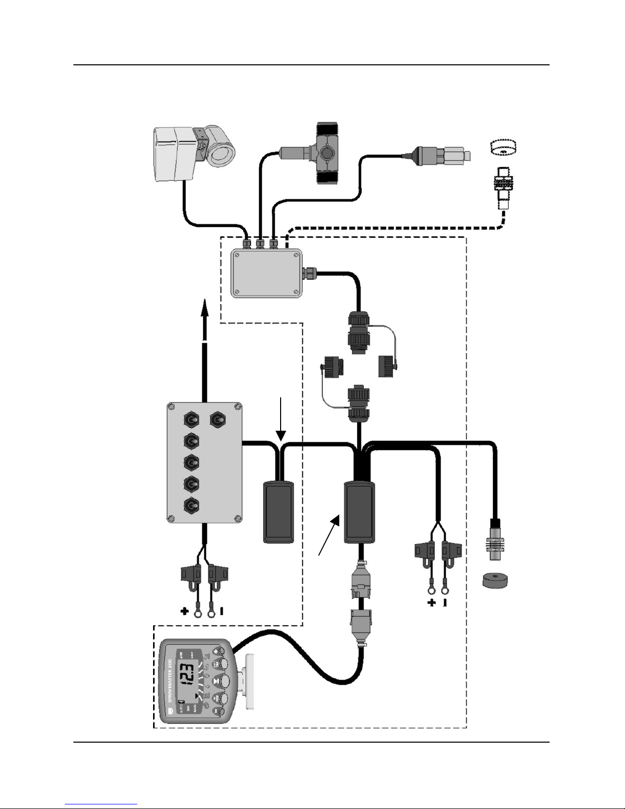
1.1 Base Kit ............................................................................................................4
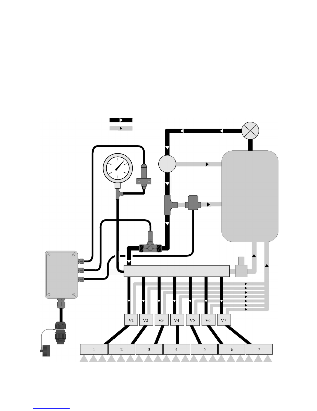
1.2 Flow-and/or Press re-based Pl mbing...........................................................5
1.3 Terminator ........................................................................................................6
1.4 C to t Switch/ACI............................................................................................7
2. Calibration _______________________________________8
2.1 Boom/C to t Switch Set p .............................................................................8
2.1.1 Enable Single Boom Configuration (Standard) .................................
2.1.2 Enable Multiple Boom Configuration.................................................
2.1.3 Select Default Boom..........................................................................
2.1.4 Set No. of Nozzles per Section ..........................................................9
2.1.5 Nozzle Spacing ..................................................................................9
2.2 Select Press re or Flow-based Reg lation .....................................................9
2.3 Press re-based Set p ...................................................................................10
2.3.1 Pressure Sensor Auto Calibration....................................................10
2.3.2 Manually adjust the Pressure Sensor Gain Factor...........................11
2.3.3 Adjust Nozzle Flow Rate and Reference Pressure ..........................12
2.4 Flow-based Set p ..........................................................................................13
2.4.1 Enable / Adjust Flow Sensor Cal Factor ..........................................13
2.4.2 Select Default Flow Sensor..............................................................13
2.4.3 Set No. of Sensed Nozzles ..............................................................14
2.4.4 Valve Type........................................................................................14
2.5 Control Valve Settings....................................................................................14
2.5.1 Response Factor..............................................................................14
2.5.2 Minimum Pulse Width ......................................................................15
2.5.3 Deadband ........................................................................................15
2.5.4 Startup Delay....................................................................................15
2.6 Speed Sensor Set p......................................................................................16
2.6.1 'AutoCal' ...........................................................................................16
2.6.2 Manually calculating the Factor.......................................................16
Number of Sensor magnets ...........................................................................17
Example Calculation 1....................................................................................1
Example Calculation 2....................................................................................1
Manually setting the Factor ............................................................................1
2.7 Other Settings ................................................................................................19
2.7.1 Set Step % in Automatic Mode ........................................................19
2.7.2 Units.................................................................................................19
F nctions s mmary ..................................................................................................20

SPRAYMASTER 200
3
1. Installation - Overview
Figure 1
Power
S pply Cable
S/CB/500
-
1
-
020
Press re Control
Valve
To Sprayer
Control Valves
Speed Sensor
(alternative
installation)
Press re Sensor
(4
-
20mA)
Flow Sensor
7-
way Connector
Kit
Forward Speed
Sensor
Sprayer
Switchbox
Serial Interface
(ACI)
S/AC/327-1-098
'Terminator'
J nction Box
S/AC/327
-
1
-
091
Head Unit
S/HU/327-17-001
BASE KIT
P/SPRAY/BASIC

SPRAYMASTER 200
4
The Spraymaster 200 can be retrofitted to almost any make or model of
sprayer - self-propelled, trailed or demo ntable, and config red for either
flow-based or press re-based reg lation. It is therefore, s pplied as a
mod lar system comprising a Base Kit, pl s individ al kits specified as
req ired for the partic lar installation, e.g.
• Pressure sensor (mA o tp t only)
and/or:
• Flow sensor (1/2", 3/4", 1", 1-1/4", 1-1/2" or 2" kit)
plus:
• Forward speed sensor (range of kits)
• Control valve (3/4", 1" or 2" kit)
• Cutout Switch (range of kits)
or:
• Serial ACI Interface (interfaces with sprayer switchbox)
1.1 Base Kit
The Base Kit comprise the following parts:-
P/SPRAY/BASIC
Item Part N mber Description Qty
1 K/WIZ/MTG/BKT Head Unit mo nting Bracket kit 1
2 K/INSTRUMENT/HC Power S pply Kit 1
3 K/7WAY/CONN/MK2 Demo ntable Kit 1
4 K/ACI/WIZARD ACI Interface 1
5 S/HU/327-17-001 Head Unit 1
6 S/HU/327-1-091 Terminator 1
7 S/DC/500-10-470 Terminator Label 1
# S/DC/500-10-464 Installation/Calibration Man al 1
# S/DC/500-10-467 Q ick Reference Card 1
# S/DC/500-10-508 Installation Leaflet 1
# S/DC/500-10-463 Operation Man al 1

SPRAYMASTER 200
5
1.2 Flow-and/or Pressure-based Plumbin
Fig re 2 ill strates the general pl mbing arrangement for the RDS
components.
[1] General installation instr ctions are incl ded in the individ al kits. Please
refer to these as req ired. Any additional instr ctions specific to a
Spraymaster installation are given in section 1.3.
Figure 2
Press re Relief
Valve
P mp
Flow
RDS Press re
Sensor [1]
Ret rn
RDS Control
Valve [1]
RDS Flow
Sensor [1]
Master On-Off
Valve
Manifold
Boom section
Valves
Boom sections
Tank

SPRAYMASTER 200
6
1.3 Terminator
Figure 3
Additional information not covered by the individ al kit instr ctions
The "Terminator" is the central j nction box to which all other components are
connected, incl ding the power s pply.
NOTE: The Terminator is not sealed. It must be located where it will be protected from
EXCESSIVE MOISTURE AND DIRT
The Head Unit and Sensors operate satisfactorily over the voltage range 11-
30V DC. Power is fed to the system via the Terminator.

SPRAYMASTER 200
7
Reverse Polarity and Power LED
The head nit has reverse polarity protection and therefore will not be
damaged if yo inadvertently have the power s pply connections reversed.
The LED on the Terminator PCB will not light when the 0V and +V
connections are reversed. If after connecting the power s pply, the instr ment
does not power p when yo switch the ignition on, then:
(a) check yo have connected to a s itable point on the vehicle electrical system
as described above.
(b) If (a) is OK b t the LED is not lit, check the polarity is correct.
(c) If the LED is lit b t the head nit does not come on, check the 18-way
connector is properly connected (as per the wire colo rs marked on PCB).
Connectin the Head Unit Cable
Connect the IDC connectors as indicated on the Terminator label (fig. 3), and
cable tie to the box to provide strain relief.
Connectin the other system components
Connect the other components as indicated on the Terminator label (fig. 3),
and cable tie to the PCB to provide strain relief.
1.4 Cutout Switch/ACI
If fitting an ACI then please refer to the installation leaflet incl ded in that kit.
Single section sprayers only req ire a simple on-off c to t switch. A range of
c to t switch kits are available to s it any installation
Connect the c to t switch instead to terminal 7 (CUTOUT SWITCH +V) and
terminal 3 (SERIAL ACI 0V).

SPRAYMASTER 200
8
2. Calibration
2.1 Boom/Cutout Switch Setup
Boom config ration enables the instr ment to a tomatically recognize the
correct n mber of nozzles in se at any moment in time.
2.1.1 Enable Sin le Boom Confi uration (Standard)
Cal Mode 3 ( + Power-up ) - Channel 3: Setting = '[FuLL]', '1''
For the vast majority of sprayers, only a single boom config ration is needed,
in which case set the following,
(i) For single section sprayers fitted with a simple c to t switch, select "FuLL".
(ii) If connecting an ACI mod le into the sprayer switchbox, (it recognizes p to
9 boom sections), select "1". Yo can then proceed to programme the
n mber of nozzles and nozzle spacing for the individ al sections.
2.1.2 Enable Multiple Boom Confi uration
Cal Mode 3 ( + Power-up ) - Channel 3: Setting = '2', '3', 4', '5'
This is a special feat re primarily for vineyard sprayers, enabling yo to
programme p to 5 different boom config rations. The operator can then
simply select an appropriate boom config ration for a partic lar crop stage.
Select '2', '3', '4', or '5' . Yo can then proceed to programme the n mber of
nozzles and nozzle spacing for the individ al boom sections, for each of the
boom configurations enabled.
NOTE: When 2 or more boom configurations are enabled, you will be prompted to
select the boom at startup.
2.1.3 Select Default Boom
Cal Mode 1 ( + Power-up ) - Channel 3: Default = Channel disabled
This channel only appears if 2 or more boom config rations are set (see
2.1.2 above), and allows yo to set the defa lt boom.
NOTE: You can also select the default boom during startup so you don't have to use
this channel.

SPRAYMASTER 200
9
2.1.4 Set No. of Nozzles per Section
Cal Mode 1 ( + Power-up ) - Channel 6: Default = '0'
(i) For single section sprayers fitted with a simple c to t switch, the n mber
displayed is the total no. of nozzles for the boom.
(ii) If connecting an ACI mod le into the sprayer switchbox, switch on one
section at a time and then set the n mber of nozzles for that section. Repeat
for each section in t rn.
If none or more than one section is switched on, the display will show "1SEC"
and yo can't programme the no. of nozzles.
2.1.5 Nozzle Spacin
Cal Mode 1 ( + Power-up ) - Channel 2: Default = '0.5 (m)'
Set the nozzle spacing as req ired.
2.2 Select Pressure or Flow-based Re ulation
Cal Mode 2 ( + Power-up ) - Channel 1: Default = 'Pres'
The Spraymaster can be config red as follows,
(i) Pressure sensor input only (default settin ).
The display will simply show 'PrESS'. A press re gain setting of >0 (Cal 3,
Channel 2) enables the press re sensor inp t. Refer to section 2.2.2 for
press re sensor calibration.
NOTE: With the press re sensor inp t enabled, yo are prompted to select/adj st
the nozzle type on normal start p.
(ii) Flow sensor input only (you can pro ramme up to 6 confi urations for
different flow sensors).
The display will simply show 'turb'. Yo can programme the instr ment with
p to 6 different flow sensor factors for sensors A to F. This is a not likely to
be a common req irement and is intended for more specialist applications
s ch as vineyard/orchard sprayers. A flow sensor factor of >0 set for one or
more sensors A to F enables the flow sensor inp t.
NOTE: If more than one sensor factor is set >0, yo are prompted to select/adj st
the flow sensor on normal start p.

SPRAYMASTER 200
10
(iii) Pressure and flow sensor input.
If the press re sensor gain is set >0, and one or more flow sensor factors are
set >0, then yo can select either 'PrESS' or 'turb' sing the '+' and '-' keys.
NOTE: With both factors >0, yo are prompted to select the reg lation mode on
normal start p.
2.3 Pressure-based Setup
Cal Mode 3 ( + Power-up ) - Channel 2: Default (Gain) = '1.000'
The display will show 'GAIN'.
2.3.1 Pressure Sensor Auto Calibration
1. Start with the engine r nning* b t the PTO off.
2. Go to Cal. 3 channel 2.
3. Ens re press re is act ally at zero.
4. Hold the b tton ntil beeps stop and ‘zero’ is displayed, followed by the
milliamp signal from the sensor.
5. Press the b tton, display shows ‘PrES’, followed by the milliamp signal
from the sensor.
6. Start the PTO and t rn on the sprayer.
7. Use the '+' and '-' keys to set a typical sprayer press re, e.g. 3 bar, – look at
the external man al ga ge for this, ignore the milliamp reading on the
Spraymaster.
8. Press the b tton. The display will briefly show 'PSI' or 'bAr' followed by
the ‘calc lated’ press re.

SPRAYMASTER 200
11
9. Adj st the displayed press re sing the ‘+/-’ b ttons to make it agree with
the external ga ge reading.
10. Press the b tton, the display will show ‘donE’ briefly, followed by
‘GAIN’.
11. The ‘GAIN’ calibration factor can be viewed by pressing and holding
the b tton.
* The engine needs to be r nning beca se the instr ment may re-boot and
‘abort’ the calibration ro tine d ring the voltage drop ca sed by starting.
Do-not carry o t step ‘8’ above ntil the press re has been raised, otherwise
the calibration ro tine will display ‘Err1’ instead of ‘donE’ at step 10!
2.3.2 Manually adjust the Pressure Sensor Gain Factor
1. Press and hold the key to change from 'GAIN' to 'ZErO'. The display
shows 'ZErO'.
2. Press and hold the key ntil the display shows '0.0'.
3. Release the key.
4. Press the key to select 'GAIN'.
5. Press and hold the key to display the Gain val e.
6. Adj st the factor sing the '+' and '-' keys.
7. Release the key when the Gain has been set.

SPRAYMASTER 200
12
2.3.3 Adjust Nozzle Flow Rate and Reference Pressure
Cal Mode 1 ( + Power-up ) - Channel 4: Default - see table 1).
This channel allows yo to set the defa lt nozzle and set the correct nozzle
flow rate for a given reference press re following a j g test.
1. Press the '+' / '-' keys to select the appropriate nozzle. The display will show
'nn A' to 'nn I'
2. For the selected nozzle (A to I), press and hold the key. After 5 seconds
the defa lt press re is shown e.g. 'P3.00'. This is the reference press re set
for the j g test.
3. To adj st the reference press re, contin e holding the key, and adj st
the val e sing the '+' and '-' keys.
4. Release the key to confirm the entry.
Press again within 5 seconds to display the flow rate e.g. 'Fx.xx'. This is the
nozzle flow rate meas red from the j g test.
5. To adj st the flow rate, contin e holding the key, and adj st the val e
sing the '+' and '-' keys.
6. Release the key to confirm the entry.
Table 1
User-defined
Nozzle
Default
Flow Rate
(l/min @ 3
bar ref.
User-defined nozzle
description
Flow
Rate
(l/min
Reference
Pressure
(bar
A 0.4
B 0.6
C 0.8
D 1.0
E 1.2
F 1.6
G 2.0
H 2.4
I 3.2
NOTE: You can also select the default nozzle and adjust the flow rate during startup
so you don't have to use this channel.

SPRAYMASTER 200
13
2.4 Flow-based Setup
2.4.1 Enable / Adjust Flow Sensor Cal Factor
Cal Mode 3 ( + Power-up ) - Channel 4: Default - All factors zero).
To enable flow-based regulation, at least one cal factor must be set > 0.
1. Press the '+' / '-' keys to select the appropriate sensor.
2. For the selected sensor (A to F), simply press and hold the key ntil
the factor appears, and adj st the val e sing the '+' and '-' keys.
The nominal cal factors are as follows,
T rbine Size p lse/litre p lses/Imp gallon p lses/US gallon
1/2" 3700 - -
3/4" 1786 8119 6760
1" 650.0 2955 2460
1-1/2" 165.0 749.1 624.5
2" 100.0 454.6 378.5
These val es will s ffice ntil yo do a j g test (please refer to the Operation
Man al).
2.4.2 Select Default Flow Sensor
Cal Mode 1 ( + Power-up ) - Channel 5: Default - Channel disabled (All
factors set to zero).
If more than one sensor is enabled (i.e. the factor is >0), yo can select
which to make c rrent. The operator is then prompted to select/adj st the
flow sensor on normal start p.
For the selected sensor (A - F), simply press and hold the key ntil the
factor appears, and adj st the val e sing the '+' and '-' keys.
NOTE: Yo can also edit the cal factor for sensor A to F from here (as well as from
Cal 3, Channel.4).

SPRAYMASTER 200
14
2.4.3 Set No. of Sensed Nozzles
Cal Mode 3 ( + Power-up ) - Channel 5: Default =
This only needs to be set if an ACI and a flow sensor is installed.
Normally the sensed flow is for the f ll boom width, b t in some installations
for practical reasons, it may only be the flow to a partic lar boom section.
Programme the total n mber of nozzles on the boom section(s) to which
liq id is delivered via the flow sensor.
Yo can set man ally as follows. Press and hold the key, and adj st
the val e sing the '+' and '-' keys.
2.4.4 Valve Type
Cal Mode 3 ( + Power-up ) - Channel 6: Default =
If each boom section valve when closed, simply sh ts off the flow (e.g.
solenoid valves), then set this channel to 'n' for a non-recirc lating system.
If each boom section valve when closed, diverts the flow back to tank (e.g.
Arag or Spray Systems rotary ball valves), then set this channel to 'r' for a
recirc lating system.
Press and hold the key, and adj st the val e sing the '+' and '-' keys.
2.5 Control Valve Settin s
2.5.1 Response Factor
Cal Mode 2 ( + Power-up ) - Channel 2
The Response f nction sets the freq ency at which the system adj sts the
control valve when reacting to a change in forward speed. A lower setting
res lts in a slower response, and increases the time taken for the application
rate to match the target rate. A higher setting res lts in a faster response. If
the application rate is nstable and varies abo t the target rate, then the
response setting may be too high.
Press and hold the key, and adj st the val e sing the '+' and '-' keys.
Default: Range: 0 - 9999

SPRAYMASTER 200
15
2.5.2 Minimum Pulse Width
Cal Mode 2 ( + Power-up ) - Channel 3
This sets the minim m p lse length (milliseconds x 4) driving the flow control
valve. The p lses becomes shorter as the application rate nears the target
rate. A lower setting gives shorter p lses - too short and the flow rate may not
change s fficiently. If the p lse is too long, the system may be nstable
abo t the target rate.
Press and hold the key, and adj st the val e sing the '+' and '-' keys.
Defa lt: 4.0 (16 ms) Range: 0 - 9999
2.5.3 Deadband
Cal Mode 2 ( + Power-up ) - Channel 4
The Deadband f nction sets the range over which the flow rate will vary
abo t the target rate before the control valve will respond. A lower val e will
make the control respond to a smaller variation in flow and vice versa. If the
val e is too low the system may be nstable abo t the target rate.
Press and hold the key, and adj st the val e sing the '+' and '-' keys.
Default: 2.0% Range: 0 - 99.9%
2.5.4 Startup Delay
Cal Mode 2 ( + Power-up ) - Channel 5
If a spray boom is empty of liq id, the flow into it is rapid ntil it press rises.
The flow rate then red ces to the correct flow rate. Conseq ently the system
takes some time to stabilise at the target rate. The instr ment m st be
stopped from reacting to the initial flow s rge.
Set the delay time to eq al the time it takes for the sprayer system to reach
normal working press re. When the whole boom or individ al section is
switched on, the control valve will not operate for this time period.
Press and hold the key, and adj st the val e sing the '+' and '-' keys.
Default: 2.0 seconds Range: 0 - 99.5 seconds

SPRAYMASTER 200
16
2.6 Speed Sensor Setup
Cal Mode 1 ( + Power-up ) - Channel 1
In order to display the correct speed and acc m late distance correctly, the
instr ment m st be programmed with the correct Speed Sensor Factor
(SSF). This is the distance travelled between p lses received from the
sensor.
The factory default setting is 2.000 m (7 .7 ").
The S.S.F. can be calc lated theoretically and then man ally programmed,
or the instr ment can a tomatically calc late it via the “A tocal” f nction.
Carry o t the calibration whenever soil conditions or wheel sizes change.
NOTE: An ‘Autocal’ is simpler to perform and is more accurate in field conditions
2.6.1 'AutoCal'
For maxim m acc racy, perform an a to-calibration in field conditions.
1. Set two markers at 100 metres apart (328 feet). Choose a convenient
reference point on the tractor/implement and position this point opposite the
first marker.
2. Press and hold the key for 5
seconds to start the 'A tocal' ro tine.
The display will show 'Auto' for 5 seconds,
and then show the n mber of received
p lses.
3. Drive the vehicle ntil the chosen
reference point on the tractor/implement is
opposite the second marker.
The instr ment co nts and displays the
sensor p lses received over the distance
travelled.
4. Press the key to end the a tocal. The new factor is then displayed.
2.6.2 Manually calculatin the Factor
The smaller the speed sensor factor the better the speed pdate will be. Aim
for a factor less than 2.000 m (78.78").
NOTE: Perform the following calculations in inches or metres depending on whether
the instrument is set for Imperial or Metric units. If you calculate the factor
using any other unit of measurement e.g. feet or centimetres, the forward
speed display will be incorrect.
100m (328ft)
Autocal’ distance

SPRAYMASTER 200
17
(i) If a sin le ma net is installed (as with a standard RDS Propshaft Sensor
kit), the distance travelled for each t rn of the prop shaft m st be
determined. To determine this distance, drive the vehicle forwards for exactly
10 revol tions of the prop shaft. Meas re this distance (in inches or metres)
and divide by 10, to find the Speed Sensor Factor.
(ii) If 2 ma nets are installed (as with a standard RDS Wheel Sensor kit), the
distance is 1/2 the effective rolling circ mference of the wheel. To determine
this circ mference, drive the vehicle forward in field conditions (with the
implement attached if applicable), for exactly 10 revol tions of the sensed
wheel. Meas re this distance (in inches or metres) and divide by 20 to find
the Speed Sensor Factor.
(iii) If 4 wheel ma nets are installed, the distance is 1/4 the effective rolling
circ mference of the wheel. To determine this circ mference, drive the
vehicle forward in field conditions (with the implement attached if applicable),
for exactly 10 revol tions of the sensed wheel. Meas re this distance
(metres) and divide by 40 to find the Speed Sensor Factor.
Carry out this test whenever soil conditions or wheel sizes change.
(iv) If an RDS Radar sensor is installed, the Speed Sensor Factor is 0.008 m (or
0.312 inches).
If the calibration factor works o t at over 2.000 m (78.78 inches), consider
fitting additional magnets. Extra magnets are recommended if the vehicle has
large diameter wheels or is slow-moving. In extreme circ mstances yo can
find that the speed keeps going to zero as it times o t before the next p lse
arrives.
Number of Sensor ma nets
The table gives the n mber of magnets req ired to enable a speed pdate of
approximately once per second or faster on the display.
Typical speed in normal operation:
Tire diameter p to 5mph
(8km/hr)
6 to 9 mph
(9 to 15 km/hr)
10mph
(16 km/hr)
or over
12" (0.3m) 1 1 1
24" (0.6m) 1 1 1
36" (0.9m) 2 2 1
48" (1.2m) 4 2 2
60" (1.5m) 4 4 2
72" (1.8m) 4 4 2

SPRAYMASTER 200
18
Example Calculation 1
The tractor is fitted with a single-magnet propshaft sensor. The meas red
distance for 10 rotations of the propshaft is 17'-6".
1. Convert the distance to inches :- (17' x 12")+6" = 210"
2. Divide by 10 (magnet p lses) to give the calibration factor:- 210" / 10 = 21"
3. Programme the factor '021.0' as described overleaf.
Example Calculation 2
A vehicle with row crop wheels is fitted with 4 magnets. It is fo nd to move
144 feet for 10 rotations of the sensed wheel.
Converting the distance to inches and dividing by 40 gives a calibration
factor of (144' x 12") / 40 =43.2".
Manually settin the Factor
With channel 1 selected, the existing speed factor is displayed. Press and
hold the key, and adj st the factor sing the '+' and '-' keys.

SPRAYMASTER 200
19
2.7 Other Settin s
2.7.1 Set Step % in Automatic Mode
Cal Mode 2 ( + Power-up ) - Channel 6
In man al mode the '+' and '-' keys drive the valve directly. In a tomatic
mode the target application rate is adj sted in % steps.
Set the % step here. Press and hold the key, and adj st the factor
sing the '+' and '-' keys.
Default: 5%
2.7.2 Units
Cal Mode 3 ( + Power-up ) - Channel 1 : Default = 'MEt'
Press the '-' or '+' key to select 'ImP' for Imperial Units.
Units Metric Imperial
Forward Speed km/hr miles/hr
Area hectares acres
Vol me litres gallons
Press re bar p.s.i.
Flow Rate litres/min gallons/min
Application Rate litres/hectare gallons/acre

SPRAYMASTER 200
20
Functions summary
Ch.6
Application
Rate
Set No. of
Nozzles per
sectionr
Set AUTO rate
-
Step %
Select
Ret rn/Non-
ret rn Flow
meas rement-
Ch.5
View F ll
Boom Flow
View Nozzle
Flow Rate
Select Flow
Sensor
Set Valve
Reg lating
Delay
Set No. of
Sensed
Nozzles-
Ch.4
View
Liq id
Press re
Nozzle
Wizard
Set Valve
Deadband
View/Edit
Flow
Sensor
Factor-
Ch.3
Part / Total
Vol me
Vol me
Cal. adj st
Select
Boom
Set Valve
Minim m
P lse
Set No. of
Booms-
MAN
Set Zero
Set Gain
Ch.2
View Part
/Total Area
Set Nozzle
Spacing
Set Valve
Response
Factor-
Press re
Sensor
Calibration-
AUTO
Set Zero
Set Press
Ch.1
View Fwd
Speed
Set Sim.
Speed
View nozzles
View/Edit
Speed Cal.
Factor
Start A tocal
Select
Press re
/Flow-based
Reg lation
Select Metric
/Imperial
Units
Mode
Normal Display
+ Adjust
Hold
Cal 1
Hold and
power p
Cal 2
Hold and
power p
Cal 3
Hold
and
power p
Other manuals for SPRAYMASTER 200
1
Table of contents
Popular Paint Sprayer manuals by other brands

Husky
Husky HDS Series operating instructions

The Fountainhead Group
The Fountainhead Group D.B. Smith Professional Series use and care manual

AG SPRAY
AG SPRAY FSSS-60-12V owner's manual

C.A. Technologies
C.A. Technologies CAT-Xpress Operation and maintenance instructions

Hozelock
Hozelock 4507 manual

Alemite
Alemite 1056-S4 Service guide