REAC RPP10 User manual

www.reac.se
USER MANUAL
RPP10
REAC POWER PACK

www.reac.se
About REAC
REAC is passionate about helping people in their daily lives, and by providing a wide range of advanced
power solutions suitable for many different applications, we hope to make people's lives a little bit easier.
Our aim is to offer our clients an excellent service, backed up by experience and know-how in the
application of advanced motion systems.
REAC's power solutions contain compact and strong electrical actuators, lift and tilt systems, control units
and hand controls. We know that our customers have different needs and therefore our products are
designed to be customized according to their application’s specific requirements.
We are confident to say that we can solve a wide range of motion problems, so please challenge us!
Contact information
REAC AB
Forsbrogatan 4
662 34 Åmål
Sweden
Phone: +46 (0)532 78 50 00
Email: info@reac.se
Web: www.reac.se

www.reac.se
Table of Contents
1INTRODUCTION ..................................................................................................................................... 1
1.1 DOCUMENTATION......................................................................................................................... 1
1.2 SYMBOLS .................................................................................................................................... 1
1.3 ABBREVIATIONS ........................................................................................................................... 1
2PRODUCT DESCRIPTION ..................................................................................................................... 2
2.1 OVERVIEW................................................................................................................................... 2
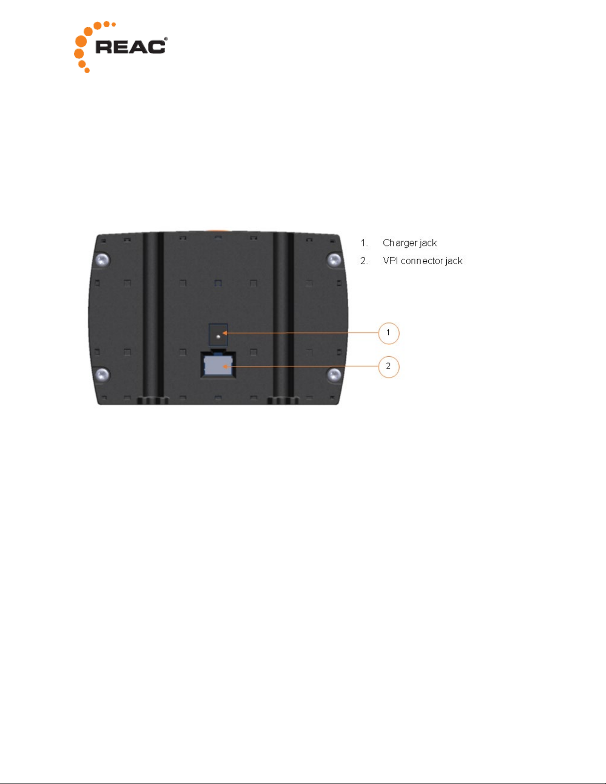
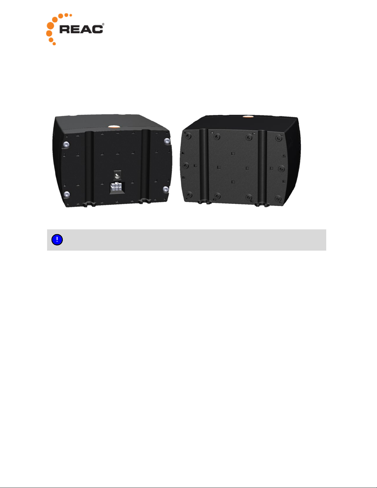
2.2 CONNECTORS.............................................................................................................................. 2
2.3 BATTERY DISCONNECTION FUNCTION ............................................................................................ 2
2.4 SAFETY FUNCTIONS ..................................................................................................................... 3
3OPERATION ........................................................................................................................................... 4
3.1 BEFORE FIRST USE....................................................................................................................... 4
3.2 CONNECTING THE CONTROL BOX .................................................................................................. 4
3.3 CHARGING THE BATTERY .............................................................................................................. 5
3.4 CHECKING BATTERY LEVEL ........................................................................................................... 5
4MAINTENANCE ...................................................................................................................................... 6
4.1 SERVICE INTERVALS..................................................................................................................... 6
4.2 CLEANING AND DISINFECTION ....................................................................................................... 6
5TROUBLE SHOOTING ........................................................................................................................... 7
5.1 REPAIRS AND REPLACEMENT ........................................................................................................ 7
6TECHNICAL DATA................................................................................................................................. 8
6.1 BASIC CHARACTERISTICS.............................................................................................................. 8
6.2 ENVIRONMENTAL CONDITIONS....................................................................................................... 8
6.3 WARRANTY.................................................................................................................................. 8
6.4 WASTE DISPOSAL......................................................................................................................... 9
6.5 LABELING .................................................................................................................................. 10

1
1 Introduction
1.1 Documentation
This manual describes the RPP10 power pack.
The following related documentation is also available:
•RPP10 Datasheet
•User Manual – RCB11 and RCB12
•User Manual – RHC10 and RHC15
1.2 Symbols
The following symbols are used in the manual:
Injury to persons can occur if these instructions are not followed.
Damage to the product can occur if these instructions are not followed.
Useful tips, recommendations, and information for efficient and trouble-free use.
1.3 Abbreviations
RCB REAC Control Box
RHC REAC Hand Control
RPP REAC Power Pack
VPI Versatile Power Interface

2
2 Product description
2.1 Overview
The REAC Power Pack RPP10 is a lead battery intended to be used as a power source.
The RPP10 is compatible with the REAC control boxes RCB11 and RCB12.
2.2 Connectors
Charger jack
The charger jack is used for connection of the battery charger.
VPI connector
The VPI connector is used for connection of the control box.
2.3 Battery disconnection function
To protect the battery from deep discharge and damaged battery cells, the control box (RCB11 or RCB12)
has a function that can disconnect the battery completely internally.
The battery is automatically disconnected when the battery level is critically low or after 18 days of
standby.

3
2.4 Safety functions
2.4.1 Battery ventilation
The RPP10 has ventilation channels (small square holes) at the back and front. The channels ensure
ventilation of the battery and also allow moisture to come out.
Do not block or cover the ventilation channels at any time.
2.4.2 Disabled motor activation while charging
If the battery charger is connected, the control box (RCB11 or RCB12) prevents any motor activation. The
reason is that the charger is not intended to run a motor and doing so might cause EMC disturbance from
the charger.

4
3 Operation
In the unlikely event of battery acid leakage and if you get it in your eyes or on your skin:
Rinse thoroughly with lots of water and contact your local healthcare for further consultation.
3.1 Before first use
Before using the RPP10 for the first time, you should charge the battery for 24 hours. This to ensure full
charge and to prolong the lifetime of the battery.
To charge the battery the first time, do the following:
1. Connect the RPP10 to a control box, see section 3.2.
2. Connect the battery charger to the RPP10 charger jack and to a wall socket.
3. Check that the LED on the charger is red, indicating charging.
4. Keep the charger connected for 24 hours.
3.2 Connecting the control box
You connect the control box to the VPI connector on the RPP10. For the RCB11, a VPI cable is needed.
The RCB12 control box has a fixed VPI cable
The VPI connector is keyed and must be inserted according to the image below. Make sure the part of the
connector that forms a straight line is facing the straight line on the RPP10 connector.
To connect the control box to the RPP10, do the following:
1. RCB11: Connect the VPI cable to the VPI connector on the control box.
2. Connect the VPI cable to the VPI connector on the RPP10.
Inserting the VPI connector the wrong way can cause damage the product.

5
3.3 Charging the battery
For an optimum lifetime, you should charge the battery as often as possible. If the battery is not charged
regularly, it will be damaged due to self-discharge. Frequent deep discharge reduces the battery life.
During charging, the RPP10 must be connected to a control box.
To charge the battery, do the following:
1. Connect the RPP10 to a control box, see section 3.2.
2. Connect the battery charger to the RPP10 charger jack and to a wall socket.
3. Check that the LED on the charger is red, indicating charging.
4. The charging time is approximately 9 hours.
When the charging is completed, the LED on the charger is green.
Only use the battery charger delivered together with the RPP10.
Charging must take place in a room with good air ventilation.
The ambient temperature must not be below 0°C or above 40°C.
If the RPP10 has not been used for a long time, it is recommended to charge the
battery for 24 hours.
3.4 Checking battery level
To check the battery charge level, you must connect the RPP10 to a RCB11 or RCB12 control box. For
more information, refer to the user manual for the control box.

6
4 Maintenance
4.1 Service intervals
To ensure safe and proper operation, regular service is required. The service interval depends on the final
application and the number of actuator cycles.
Between the planned service points, regular inspection and maintenance should also be performed.
The following maintenance schedule is suggested:
Initially
Regularly
At planned
service
Power pack box
Make sure the RPP10 box is securely fastened.
Cover
Check the plastic housing for mechanical damage (cracks).
Cables
Make sure the cable that connects the RPP10 to the control
box is firmly affixed.
Battery
Before use, make sure at least 1 green battery indicator LED
is lit on the hand control.
4.2 Cleaning and disinfection
Cleaning instructions
Clean with a damp cloth or with a brush and water (water must not be under pressure)
Make sure all connectors are plugged during cleaning. This to prevent ingress of water.
Do not wash directly with a high-pressure cleaner.
Do not use a steam cleaner.
For disinfection, it is recommended to use soap or equal and clean with a damp cloth.
Cleaners and disinfectants must not:
•be highly alkaline or acidic,
•contain caustic agents,
•change the structure of the surface of the plastic or the adhesives.

7
5 Trouble shooting
Problem
Probable cause
Description
Solution
System
appears
“dead”
Low battery level.
When the level is critically
low, the battery is
automatically disconnected
to protect the battery1.
Charge the battery.
Loose contact
between the RPP10
and control box.
Nothing happens when
trying to activate the system.
Make sure the RPP10 is
properly connected to
control box.
Battery disconnect
functionality
activated.
Nothing happens.
Connect the charger (see
section 3.3).
Battery is worn out.
The battery level indicators
on the hand control drop
quickly after full charge.
Service is needed.
No
Charging
Charger cable not
connected.
The LED on the charger is
not indicating charging.
Make sure the cable is
properly connected to the
RPP10 and a wall socket.
Damaged batteries.
Charger connected for
several hours, but no
charging indication.
Service is needed.
5.1 Repairs and replacement
To avoid risk of malfunction, all repairs must be carried out by authorized REAC workshops or by a REAC
appointed representative. Products under warranty must also be returned to an authorized REAC
workshop.
Do not open the product. Damage to the product can occur.
1Before this happens, the control box will give a warning sound and the low battery LED on the hand control will flash.

8
6 Technical Data
6.1 Basic characteristics
RPP10
Capacity
2.9 Ah
IP class
IPX6
Battery type
Lead
Charge time
9 h
Weight
2.4 kg
Flammability rating
UL94 V-0
Color
Black (RAL9005)
White (RAL9016)
6.2 Environmental conditions
RPP10
Operating
Ambient temperature
-15 °C to +50 °C
Relative humidity
15% to 90%
Atmospheric pressure
700 to 1060 hPa
Storage
Ambient temperature
-20 °C to +50 °C
Relative humidity
15% to 90%
Atmospheric pressure
700 to 1060 hPa
General
Oxygen rich environment
No
Label reading environment
50 cm / 500 lx
Do not use the product outside the specified limits. Personal injury and damage to the
product can occur.
Warranty
There is a warranty on REAC products against manufacturing faults. The warranty period begins on the
purchasing date of the product and applies for 12 months. Warranty exclusions: REAC is entitled to deny
any warranty if:
· The product has not been correctly used or the product usage specifications (load, environment,
temperature, duty cycle, voltage, current, etc) have not been respected.

9
· The product has not been correctly maintained.
· The product has been tampered with.
· The product has been be exposed to violent or abrasive treatment.
Nonconformities due to age of the product (for example, discolouring of painting) are excluded from
warranty.In case of doubt regarding the existence of a defect or if an inspection is required, REAC
reserves the right to request the return of the product.
Any additional warranty obligations for parts replaced free of charge or for any service provided without
charge under this warranty shall be excluded.
Warranty of the replaced parts under warranty period will end on the date of expiry of the warranty period
of the product concerned.
.
6.3 Waste disposal
All REAC products are marked with this symbol. According to Waste Electrical and Electronic
Equipment (WEEE) Directive 2002/96/CE, the symbol indicates that the product must be taken
to a proper disposal site and cannot be discarded in normal household waste.
RPP10 consist of several parts with different material, which means it cannot be disposed as one single
item. It is recommended (at disposal) to disassemble and divide the product as much as possible into
feasible waste groups to be able to recycle the product in the most environmentally friendly way.
The following waste groups have been identified for the RPP10:
Cables
Electronics
Metal
Plastic
Batteries
RPP10
•Internal harness
•Connection cable
•Connector circuit board
•Charger circuit board
•Screws
•Cover
•2 × 12 V Pb
Some of these main groups can be divided into sub-groups. Metal can, for example, be divided into iron,
stainless steel, and aluminum and alloy steel. Plastic can, for example, be divided into ABS, PA, PE, and
PP. All REAC plastic units are provided with an interior code for plastic types and fiber contents.

10
6.4 Labeling
The following symbols are used on the label of REAC control system products.
Rated voltage (24 VDC)
IPXX Ingress of particles (first character) and water (second character) as per
EN60529.
IEC 60417-5840: Patient part of type B
IEC 60417-5957: For indoor use only
WEEE compliant
CE-label attached based on Low Voltage Directive and EMC Directive.
ISO 7010-M002: Risk(s) mitigated in accompanying documents
Label example - product

11
The following symbols are used on the packaging of REAC control system products.
Manufacturer/manufacturing date.
Do not use if package is damaged.
Fragile, handle with care
Keep dry
Temperature limits
Relative humidity limits
Atmospheric pressure limits
Consult instructions for use
Label example - packaging

© REAC, February 2021, Issue 5.0
REAC is continuously developing our products and can make changes without prior notice. Therefore we can’t guarantee that the
information stated on our webpage or in our written material always is up to date, nor can we take responsibility for any
misinterpretation of our written context. Technical specification might change due to load and external circumstances. REAC products
shall be tested in its intended application before use.
REAC AB
Forsbrogatan 4
662 34 Åmål, Sweden
REAC Poland Sp. z o.o
Ul. Sulejowska 45
97-300 Piotrków Trybunalski, Poland
www.reac.se
E-mail: [email protected]
Phone: +46 532 78 50 00
Table of contents