Recoil R65 User manual

POWERSPORTS CAN SPEAKERS R65
R65
POWERSPORTS CAN SPEAKERS
User Manual

POWERSPORTS CAN SPEAKERS R65
Thanks for purchasing Recoil Powersports Speakers for your system. Recoil has
been bringing great designed and engineered audio products to life. We hope
that the addition of these speakers to your audio system bring you a lot of
enjoyment.
Recoil speakers are designed and engineered in the USA to reproduce great
sound quality for extreme environments. We highly recommend that your new
speakers be installed by an authorized Powersporfs dealer.
If you decide to install the speakers by yourself, please thoroughly read through
this manual before getting started, so you make the process successful. This
manual will familiarize you with the speakers; and how best to install them and
guide you through the proper installation process and procedures.
Please contact your authorized Powersports dealer if you have any questions
regarding the instructions in thís manual. If you require additional assistance
contact [email protected]
RECOIL POWERSPORT SPEAKERS
· 1 pair- R65 speakers
· 2 Sets - Mounting hardware
· 4 pairs - 1.5", 1.75", 1.875" & 2" rubber inserts
· 2 pairs - aluminum mounting bands
Roll Cage/Bar fitment:
The R65 comes with 4 pairs of rubber inserts and 2 pair of Aluminum mounting
bands.
* Before installing please measure your bars diameter
SUPPLIED HARDWARE/PARTS;
1.5"
Rubber
Insert
1.75"
Rubber
Insert
1.875"
Rubber
Insert
2.0"
Rubber
Insert
1.5-1.75"
Band
1.875-2.0"
Band

POWERSPORTS CAN SPEAKERS R65
DIMENSIONS
MOUNTING
Step 1: Remove can speakers from
the packaging and ALL hardware
Step 2: Find a GOOD location that allows
for easy wiring of the speakers (and LED
lights) - PLUS that it does NOT impair your
movement around the location.
Step 3: Using a philips head screwdriver,
remove the screw that holds the mount-
ing band to the tower speakers.
Step 4: Measure the roll cage bar and use
the included rubber insert that fits YOUR
roll cage bar. Place the rubber insert onto
the bar and then clip the band over the
rubber insert.
mounting band
Mounting base
rubber insert
1.0"(25.0mm)
6.89"(Φ175.0mm)
9.9"(251.8mm)
2.24"(Φ56.8mm)
8.27"(209.8mm)

Tie-Wrap
POWERSPORTS CAN SPEAKERS R65
Step 5: Slide the can speaker into the
mounting band and line up the mounting
hole. Insert the 1/2"(13mm) bolt thru the
mounting hole and tighten with a phillips
screwdriver.
IMPORTANT NOTE:
Blue Loctite is recommended for thread-
ed hardware .
Step 6: Once the location is finalized,
tighten the mounting screw with a phillips
screwdriver.
Step 7: If need be, rotate the speakers for
best dispersion, This is easily done by
locating the 5/16"(8mm) nuts on the each
side of mounting band. Once located
release it using a wrench (or phillips
screwdriver) so that you may rotate the
speaker/enclosure to the desired angle.
Once there ...lock the nut down.
IMPORTANT NOTE:
Rotation is limited to 70 Degrees.
DO NOT exceed that range of motion!!
Step 8: Tie-wrap cabling. A very simple
solution is to NOT drill a hole in your roll
cage bar and simple tie-wrap the speak-
er/LED wire to the roll bar.
1/2"(13mm) Wrench
1/2"(13mm) Nut
70 Clamp
Rotation

Some wake towers allow for the wiring to be ran though the tower. Locate the
desired location of the speaker, drill a 3/4" hole and route the speaker wire with
the attached connector down through the wake tower. Drill a hole at the
bottom and then continue to the amplifier for termination. Use a grommet when
running any wire thru a metal hole.
POWERSPORTS CAN SPEAKERS R65
CAN WIRE ROUTING
Option 1:
R65 speakers are terminated with a waterproof DIN connector. The pigtail
contains a (+) and (-) 18 AWG speaker wire and a female Micro DIN connector
for termination of the RGB lighting. Terminate the speaker wires to the speaker
wire output on the amplifier. You wilI need to purchase separately our
RGBLED-4C controller with (4) male Micro DIN outputs that will control (4) speak-
ers via the Micro DIN connector located on the pigtail. The RGBLED-4C is APP
driven with the EZ RGB APP which is available for both IOS and Android.
RGB / SPEAKER WIRE TERMINATION
12 ft. 6 Conductor Speaker/RGB wire
ATTACHED LED/SPEAKER PLUG
Micro-DIN
Speaker Wiring
Tower Tube
3/4" Hole
Rubber grommet
(Not included...But recommended)

POWERSPORTS CAN SPEAKERS R65
Option 2:
Terminate the speaker wire to the speaker wire output on the amplifier. Then
remove the Micro DIN connector, strip and terminate the internal wiring as
follows: DC 12V (+) to the black RGB wire and then pick one set of color combi-
nations listed below.
NOTE: It is possible to "mix" colors WITHOUT using a RGB controller Follow the
1.Green Color: Green Wire( Negative)+Black Wire(Positive)
2.Red Color: Red Wire( Negative)+Black Wire(Positive)
3.Blue Color: Blue Wire ( Negative)+Black Wire(Positive)
4.Purple Color: Red+Blue Wire ( Negative)+Black Wire(Positive)
5.Yellow Color: Red+Green Wire( Negative)+Black Wire(Positiv)
6.Cyan Color: Blue+Green Wire( Negative)+Black Wire(Positive)
7.White Color: Blue+Green+Red Wire( Negative)+ Black Wire(Positive)
LED/ SPEAKER WIRING CONFIGURATION
BASIC COLOR COMBINATIONS BELOW
LED WIRING
(Inside Micro-DIN)
SPEAKER
WI RI NG
Black (+)
Green (-)
Red (-)
Blue (-)
Black SPKR (-)
Red SPKR (+)

POWERSPORTS CAN SPEAKERS R65
SPECIFICATIONS:
INSTALLATION CONSIDERATIONS:
MODEL
R65
Passive Radiator:
Power Rating:
Sensitivity:
MidBass:
Tweeter:
Nominal Impedance:
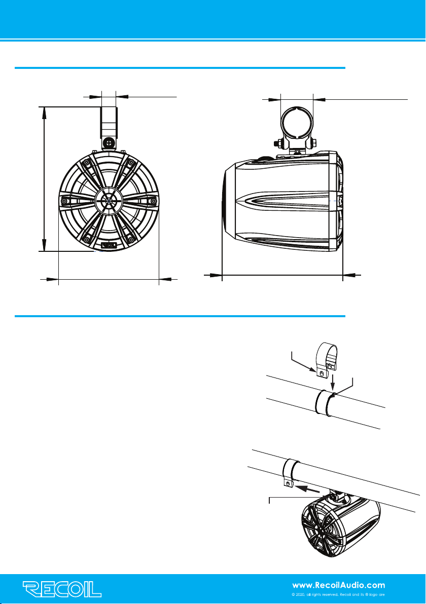
Mounting Dimensions (enclosure):
Length:
Width:
Height:
SPECIFICATIONS
4"(102mm)
160WMAX/80WRMS
85 dB @ 1W/1M
6.5"(165mm) Water-Proof Speaker
1"(25.4 mm) PEI Tweeter
4 ohm
8.27"(209.8mm)
6.89"(175mm)
9.91"(251.8mm)
TYPE
6.5" Can Speaker
1. Be sure to carefully read and understand the instructions before attempting to
install these speakers.
2. For safety, disconnect the negative battery terminal from the battery prior to
beginning the installation.
3. For easier assembly, we suggest you have all your tools handy: drill, Allen
wrench set, crimps, soldering iron, wire strippers, heat -shrink, etc.
4. Use high quality, waterproof connectors for a reliable installation and to mini-
mize signal or power loss.
5. Think before you drill! Be careful not to cut or drill into gas tanks, fuel lines, brake
or hydraulic lines, vacuum lines or electrical wiring when working on any vehicle.
If installing in a boat, take care not to cut or drill through the main hull.
б. lf possible, do not run wires near fuel lines or power. Running the wires inside the
hull area provides the best protection.
7. Avoid running wires over or through sharp edges. Use rubber of plastic gromets
to protect any wires routed through metal — especially the tower.
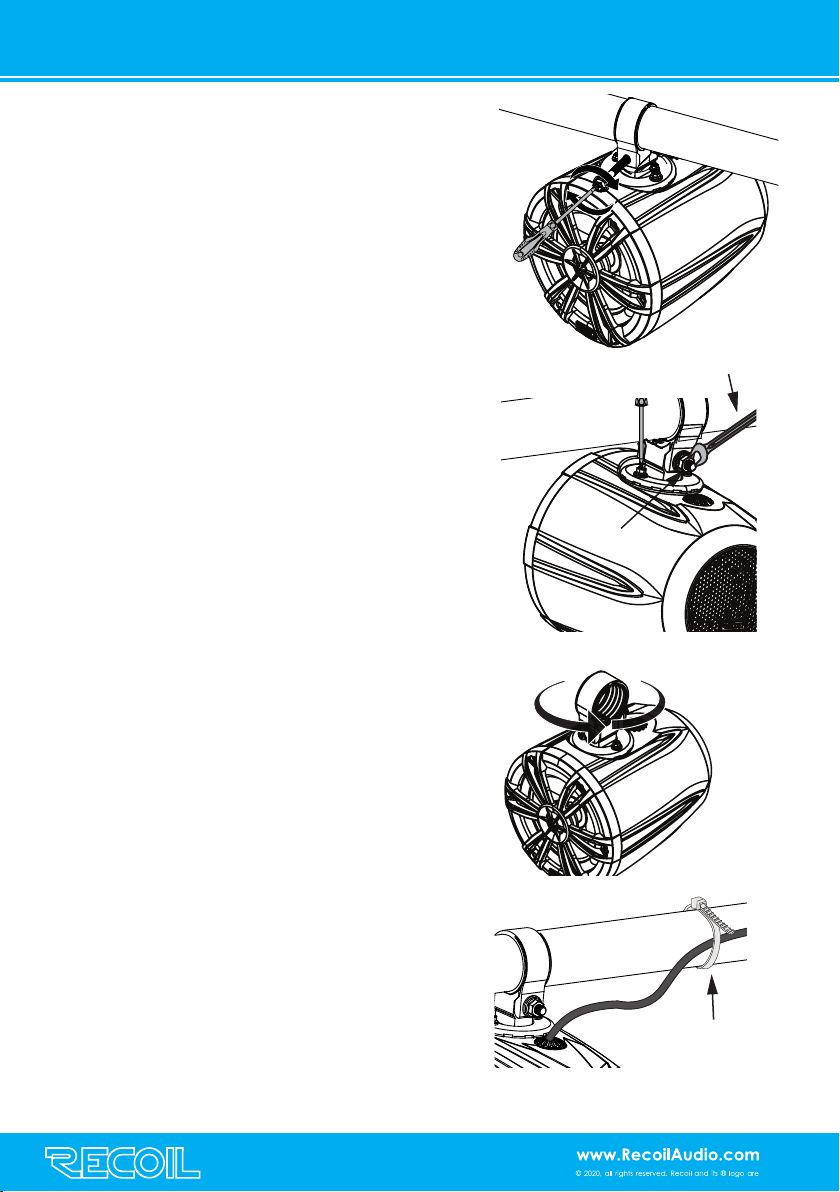
8. Make sure the mounting clamps are tight before leaving the dock or cruising
off-road.
Table of contents
Other Recoil Car Speakers manuals