manuals.online logo
Brands
  1. Home
  2. •
  3. Brands
  4. •
  5. red roo
  6. •
  7. Tiller
  8. •
  9. red roo RH918 Use and care manual

red roo RH918 Use and care manual

Other manuals for RH918

1

Other red roo Tiller manuals

red roo GT622 Use and care manual

red roo

red roo GT622 Use and care manual

red roo GT622 Operating instructions

red roo

red roo GT622 Operating instructions

Popular Tiller manuals by other brands

WIL-RICH 2500 Operator's manual

WIL-RICH

WIL-RICH 2500 Operator's manual

MTD 410R parts list

MTD

MTD 410R parts list

Viking HB 685 instruction manual

Viking

Viking HB 685 instruction manual

SMASH TLG415 instruction manual

SMASH

SMASH TLG415 instruction manual

FarmBoy FB-IC-209P user manual

FarmBoy

FarmBoy FB-IC-209P user manual

Craftsman 247.29931 Operator's manual

Craftsman

Craftsman 247.29931 Operator's manual

MTD FRT Series Operator's manual

MTD

MTD FRT Series Operator's manual

Craftsman 917.298353 owner's manual

Craftsman

Craftsman 917.298353 owner's manual

Troy-Bilt Colt FT Operator's manual

Troy-Bilt

Troy-Bilt Colt FT Operator's manual

MTD OHV Series Original operating instructions

MTD

MTD OHV Series Original operating instructions

YAT YT5601-01 Assembly, Use, Maintenance Manual

YAT

YAT YT5601-01 Assembly, Use, Maintenance Manual

Craftsman 917.296010 owner's manual

Craftsman

Craftsman 917.296010 owner's manual

Scheppach MTP560 Translation from the original instruction manual

Scheppach

Scheppach MTP560 Translation from the original instruction manual

GARDEN WAY 12194 owner's manual

GARDEN WAY

GARDEN WAY 12194 owner's manual

Classen STAND-AER SA-25 Operator's manual and parts list

Classen

Classen STAND-AER SA-25 Operator's manual and parts list

Altrad ATIKA BH 1400 N Original instructions, safety instructions, spare parts

Altrad

Altrad ATIKA BH 1400 N Original instructions, safety instructions, spare parts

DR PILOT 2 Safety & Operating Instructions

DR

DR PILOT 2 Safety & Operating Instructions

AL-KO TL 1820 Instructions for use

AL-KO

AL-KO TL 1820 Instructions for use

manuals.online logo
manuals.online logoBrands
  • About & Mission
  • Contact us
  • Privacy Policy
  • Terms and Conditions

Copyright 2025 Manuals.Online. All Rights Reserved.

GT622
GARDEN TILLER
Commercial Environmental Equipment
Operation, Safety & Maintenance Instructions
™
RH918
ROTARY HOE
Commercial Environmental Equipment
GT622
Commercial Environmental Equipment
Online Demonstration Available at: www.redroo.com/products/rotaryhoe
2
INTRODUCTION
Dear Valued Customer,
Congratulations! You are now the proud owner of the Red Roo Model RH918
Rotary Hoe. Please take a moment of your time to look over the following
method of operation. Pay particular attention to the safety and
information. Familiarise yourself with the rotary hoe, its characteristics
and
operating instructions.
If you have any questions or need any replacement parts in the future please
contact us at your convenience on our toll-free phone number 1300 133 767
or redroo.com
You alone know the operational demands and special conditions affecting
the equipment in your situation and therefore assume the responsibility
for developing, carrying out and enforcing the safety concepts which
apply to your own operation to effect the greatest safety for yourself and
the people around you.
™
1301-0054-A
© Copyright 2013
Red Roo Sales & Service Company Pty. Ltd.
Red Roo Customer number
Machine Identification Record
Machine model number ________________________
Machine serial number
Engine manufacturer
Engine model number
Engine serial number
THANK YOU for your patronage, confidence and support in
Red Roo Commercial Environmental Equipment.
Machine Indentication Record:
Red Roo Customer number
Machine model number
Machine serial number
Engine manufacturer
Engine model number
Engine serial number
2
INTRODUCTION
Dear Valued Customer,
Congratulations! You are now the proud owner of the Red Roo Model RH918
Rotary Hoe. Please take a moment of your time to look over the following
method of operation. Pay particular attention to the safety and
information. Familiarise yourself with the rotary hoe, its characteristics
and
operating instructions.
If you have any questions or need any replacement parts in the future please
contact us at your convenience on our toll-free phone number 1300 133 767
or redroo.com
You alone know the operational demands and special conditions affecting
the equipment in your situation and therefore assume the responsibility
for developing, carrying out and enforcing the safety concepts which
apply to your own operation to effect the greatest safety for yourself and
the people around you.
™
1301-0054-A
© Copyright 2013
Red Roo Sales & Service Company Pty. Ltd.
Red Roo Customer number
Machine Identification Record
Machine model number ________________________
Machine serial number
Engine manufacturer
Engine model number
Engine serial number
THANK YOU for your patronage, confidence and support in
Red Roo Commercial Environmental Equipment.
RH918
3
™
Table of Contents
41-43 Keysborough Avenue, Keysborough, Victoria, Australia 3173
Tel.: +61 (03) 9769 0455 Fax: +61 (03) 9769 0366
Outside Melbourne Metro: Tel.: 1300 133 767 Fax: 1300 133 757
redroo.com
RED ROO SALES & SERVICE COMPANY PTY. LTD.
ASSEMBLY INSTRUCTIONS 4
ABOUT THIS MANUAL 5
SAFETY INSTRUCTIONS 6
OPERATING INSTRUCTIONS 7
SERVICE INFORMATION 8
HOUR METER 8
TROUBLESHOOTING
9
13
WORKSITE ASSESSMENT 12
WEB INFORMATION
18
RH918 ASSEMBLY ILLUSTRATIONS
RED ROO WARRANTY 19
3
™
Table of Contents
41-43 Keysborough Avenue, Keysborough, Victoria, Australia 3173
Tel.: +61 (03) 9769 0455 Fax: +61 (03) 9769 0366
Outside Melbourne Metro: Tel.: 1300 133 767 Fax: 1300 133 757
redroo.com
RED ROO SALES & SERVICE COMPANY PTY. LTD.
ASSSEMBLY INSTRUCTIONS 3
ABOUT THIS MANUAL 4
SAFETY INSTRUCTIONS 5
OPERATING INSTRUCTIONS 6
SERVICE INFORMATION 7
HOUR METER
HONDA GX160 SCHEMATIC
ROBIN EX17 SCHEMATIC
HYDRAULIC SCHEMATIC
7
8
9
8
TROUBLESHOOTING
11
SPECIFICATIONS 10
ENGINE CONTROLS
12
WORKSITE ASSESSMENT 13
14
GT622 ASSEMBLY ILLUSTRATIONS
RED ROO WARRANTY 18
ASSEMBLY
INSTRUCTIONS
1. Remove the tiller from shipping crate. Please inspect immediately for any damage and
notify the shipping company and Red Roo, right away if any is found.
2. Check reservoir according to instructions in service information on the following page.
3. Fill the engine with fuel and oil according to the engine manual.
4. When documentation refers to “right side” or “left side”, it is relative to the operator’s
position with both hands on the handlebars.
ASSEMBLY INSTRUCTIONS 4
ABOUT THIS MANUAL 5
SAFETY INSTRUCTIONS 6
OPERATING INSTRUCTIONS 7
SERVICE INFORMATION 8
HOUR METER 8
TROUBLESHOOTING 9
WORKSITE ASSESSMENT 12
RH918 ASSEMBLY ILLUSTRATIONS 13
WEB INFORMATION 18
RED ROO WARRANTY 19
A SSEMBL Y I NST RUCT I ONS
1. Remove rotary hoe from shipping crate.
Screw the handle bar adjustment crank into the lower handle bar adjuster pin.
Fasten handle bar to rotary hoe using the 1/2" x 3" bolt supplied.
Arrange hoses down handle bar tube and fasten to the tube with tie wraps provided.
Adjust clutch cable by removing all slack in lever.
Check reservoir according to instructions in service information on page eight (8).
Fill engine with fuel and oil according to the engine manual.
Free wheel hubs: Pull one free wheeling pin slightly, using the split ring. Rotate the pin until
the 1/8" diameter roll pin aligns with the slot mounting plate. Allow the pin to slide through
the slot. Repeat for the other wheel. Roll the rotary hoe until each pin drops into a hole in the hub.
The hubs are now locked.
Uncoil the wire for the remote engine on/off switch. Route wire along the clutch cable to the
engine and secure with the cable ties provided. Splice this wire to the kill switch wire on the
engine with the electrical splice provided.
2.
3.
4.
5.
6.
7.
8.
9.
15
PARTS LIST FOR SG-350 DRAWING 2
Item No. Part No. Description Quantity
1 0217-0001 Brake, Hand 1
2 0301-0014 Cable, Hand Brake 1
3 0209-1040 Bolt 2
4 2301-0507 Washer 4
5 1401-0003 Nut 2
6 0209-0840 Bolt 2
7 2301-0505 Washer 4
8 1401-0508 Nut 2
9 0201-0002 Brake, Band Assy 1
10 0217-0002 Brake, Drum Assy 1
11 1604-0035 Pin, Cable 2
12 1913-0077 Spacer 1
13 1401-0008 Nut 2
14 0209-0670 Bolt 1
15 0705-0008 Guide (Rope Start) 1
16 2301-0034 Washer 1
17 1401-0503 Nut 1
18 0214-0106 Bracket 1
You aloneknowtheoperationaldemandsandspecial
conditionsaffectingtheequipment in yoursituationand
thereforeassumetheresponsibilityfordeveloping,
carrying out, and enforcing the safety concepts which
apply to yourownoperation to effectthegreatestsafety
for yourself and the people around you.
Commercial Environmental Equipment
™
4
SAFETY FIRST – Stay Alert, Do Not Get Hurt
Read this section before use!
The RH918 Rotary Hoe is designed to cultivate soilandtherefore is potentially
dangerous. Careless or improper use may result in serious or even fatal injury.
It is important that you read and understand the contents of this manual and that you allow only
mature, adult individuals to operate your Rotary Hoe. It is your responsibility to ensure that any
individual who operates your rotary hoe has read and understood this manual.
Never use the rotary hoe for any other purpose than soil cultivation. The machine is designed for
this purpose only. Any other use may result in serious or even fatal injury and/or damage to the
machine.
ABOUT THIS MANUAL
The information contained in this manual has been prepared to assist you in the safe operation, the
routine maintenance and general care of your Red Roo product. By following these guidelines, you
may look forward to years of reliable service from your Red Roo. Information is catergorised and
denoted by the following symbols and phrases:
SAFETY FIRST
DANGER!
WARNING!
CAUTION!
4
HAZARD SYMBOLS & MEANINGS
Before operatingthisMachineread
andobserve all Warnings, Cautions
andInstructions on theMachineand
in theOperatorsManual. Although the
reading of informationcontained in
thismanualdoesnoteliminatethe
risk involved in operatingthis
machine,yourunderstanding of this
informationwill promotethe correct
andsafeuse of yourmachine.Failure
to followInstructionsandSafety
Informationcouldresult in serious
injury or death.
Read Hearing
Protection
Eye
Protection
Wear
Gloves
Cut Hand
No
Bystanders
Don’t Remove
Guards
Moving
Parts
Hot
Surfaces
Don’t Refuel
Hot Engine
Keep Clear
Rotating Tynes
Explosion
Electrical
Shock
Toxic
Fumes
Remove Spark
Plug Leads
5
Identifies general safety practices.
An instruction which, if not followed, could result in serious or fatal injury.
An instruction which, if not followed, could result in personal injury.
An instruction which, if not followed, could damage machine components.
USE COMMON SENSE AND PLENTY OF IT
1) DO NOT allowanyperson to operate the rotary hoe withoutfirst readingandunderstanding the
safety precautionsandoperatinginstructions. Readandunderstand the enginemanual.KNOW
THE CONTROLS AND HOW TO STOP THE ROTARY HOE QUICKLY IN AN EMERGENCY.
2) NEVER allow children or untrained adults to operate the rotary hoe.
3) ALWAYSwearprotectiveclothingwhenoperating the rotary hoe.
This includes, but is not limited to: safety glasses, loose fitting gloves,
steel capped boots and hearing protection. NEVER wear loose fitting
clothing or jewellery when operating the rotary hoe. Keep all clothing away from moving parts. Items
could become caught in the machine, resulting in injury.
4) ALWAYS operate the rotary hoe in a well lighted area.
5) ALWAYSmakecertainthat the tyne engagement control lever is in the “neutral”positionprior to
starting the engine. The TYNE ENGAGEMENT CONTROL LEVER on the left handlebar is for the
6) ALWAYS operate rotary hoe on level groundonly. Police the area before
rotary hoeing. Remove anyforeignobjects in the diggingarea(egbricks, rocks,
wire and sticks). Locate andmarkanysprinklerheads, water pipes, gaslines,
electrical and telephone cables or any other hazard either below or above ground.
7) DO NOT allow otherpersonsnear the rotary hoe. It is the responsibility of the operator to keep
bystanders and animals a minimum of 6 metres (18ft) away from the machine while it is in operation.
9) NEVERoperate the rotary hoe when fatigued.ALWAYS BE ALERT! If youbecometiredwhile
operating the rotary hoe, takeabreak. If youhaveanyphysical or mental conditionthatmay be
aggravated by strenuous work, consult your physician before you operate this equipment.
NEVER operate the rotary hoe under the influence of medication, alcohol or drugs.
10) ALWAYSKEEP YOUR HANDS,FEETAND BODY AWAY FROM THE DIGGING
AREA WHILE ENGINE IS RUNNING.
11) NEVER operate the unit without the safety guards in place and in working order.
Keep the unit well maintained and in good working order
12) DO NOT leave the machine unattended while the engine is running.
13) DO NOT overspeed the engine or alter the governor settings. Excessive speed is dangerous and will
shorten engine life.
14) NEVERoperate the rotary hoe in an enclosedarea.Engineexhaustcontainscarbon
monoxide, an odourless and tasteless poison.
15) STOP the engine, disconnect the spark plug lead and allow engine to cool before inspecting or
performing maintenance on the rotary hoe.
16) REFUELLING
*SHUT OFF ENGINE. DO NOT REFUEL AN ENGINE WHILE OPERATING!
* Allow engine to cool. Minimum 5 minutes.
*USE UNLEADED FUEL ONLY. Use clean, fresh unleaded fuel.
*Do not mix oil with unleaded fuel.
* Do not over-fill fuel tank. Allow space for fuel expansion.
* Do not smoke near equipment.
* Allow no naked flame or hot material in refuelling area.
* Use only approved fuel containers and funnels. Remember, fuel is a potential hazard.
* Refer to engine owners manual for full details.
SAFETY INSTRUCTIONS FOR RH918 USERS
Outdoor Power Equipment Institute Recommendations
WARNING TO PURCHASERS OF INTERNAL COMBUSTION
ENGINE EQUIPPED MACHINERY OR DEVICES:
The equipmentwhich you have purchased doesnothave a spark arrester muffler. If thisequipment
is to be used on any forest and brush covered land or grass covered unimproved land, the law may
requirethatasparkarrester muffler be installedand be in effectiveworkingorder. The spark
arrester must be attached tothe exhaust system and comply with local authorities by-laws.
5
Hydraulic oil is under extreme pressure and can get under skin and burn or poison. Check for
leaks with cardboard.
8)
operator’s protection. All motion stops when the control lever’s released!
DO NOT TAPE THE CONTROL LEVER UP or otherwise by-pass this safety feature!
6
MAXIMUM ANGLE
OF OPERATION
DO NOT EXCEED
15º ANGLE
USE COMMON SENSE
AND PLENTY OF IT
SAFETY INSTRUCTIONS FOR HT912USERS
INSTRUCTIONS
DO NOT allow any person to operate the
hydraulic trencher without first reading and
understanding the safety instructions and
NEVER allow children to operate the hydraulic trencher.
ALWAYS use hydraulic trencher in a well lighted area.
ALWAYS make certain that all control clutches are in
the “disengaged” position prior to starting the engine.
The safety clutch lever/Operator Presence Control on
the left handlebar is for operator protection. DO NOT
tape down or otherwise bypass this Safety Device.
NEVER wear loose fitting clothing or jewellery when
operating the hydraulic trencher. Keep all clothing
away from moving parts. Item could become
caught in the machine, resulting in injury.
ALWAYS wear protective
clothing when operating
the hydraulic trencher.
This includes, but is not limited to, safety glasses, hard hat
loose fitting gloves, steel capped boots and hearing protection.
operating instructions. KNOW THE CONTROLS AND
HOW TO STOP THE HYDRAULIC TRENCHER QUICKLY
IN AN EMERGENCY.
1)
2)
3)
4)
Police the area before trenching. Remove any foreign
objects in the digging area eg bricks, rocks, wire and
sticks. Locate and mark any sprinkler heads, water
pipes, gas lines, electrical and telephone cables or any
other hazard either below or above ground.
5)
DO NOT leave the machine unattended while the engine
is running. DO NOT park on incline or park
perpendicular to slope. DO NOT freewheel down incline.
7)
DO NOT overspeed the engine or alter the governor
settings. Excessive speed is dangerous and will
shorten engine life
8)
NEVER operate the hydraulic trencher when fatigued.
ALWAYS BE ALERT! If you get tired while operating
the hydraulic trencher, take a break. If you have any
type of physical or mental condition that may be
aggravated by strenuous work, consult with your
physician before you operate this equipment. NEVER
operate the hydraulic trencher under the influence of
medication, alcohol or drugs.
9)
NEVER operate the unit without the safety
guards in place and in working order. Keep
the unit well maintained and in good working order
Remove the hydraulic trencher from its
trailer. Use caution.
Police the area. Remove any
foreign objects from the area.
Identify and mark the location of sprinkler heads,
gas pipes, telephone cables, etc.
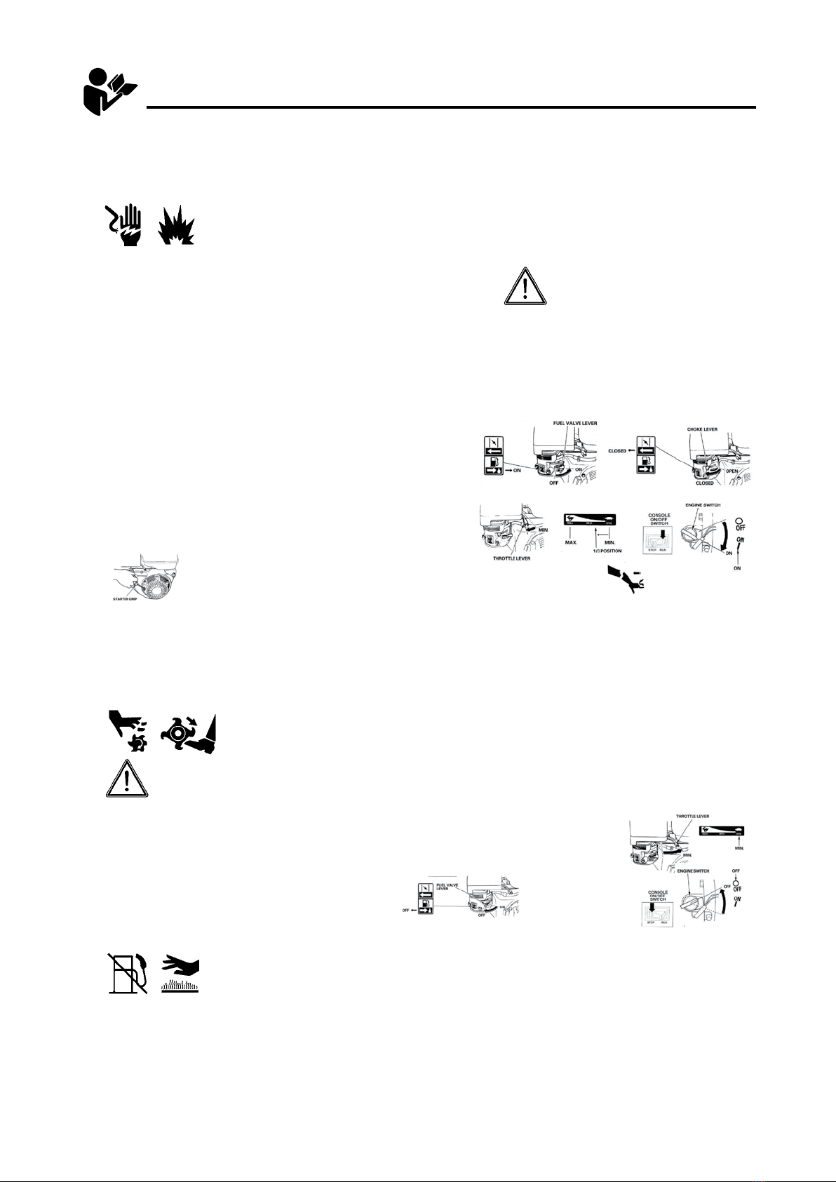
IGNITION: Must be in “ON” position to start. “OFF”
to stop.
ENGINE: Throttle cable controls engine speed.
Operate at full throttle (all the way forward).
WHEEL DRIVE CONTROL LEVER: Controls wheel
speed forward or reverse after clutch lever is engaged.
DIGGING BOOM CONTROL LEVER: Raises and lowers
the digging boom.
DIGGING CHAIN CONTROL LEVER: must be in “ON”
position BEFORE clutch lever is depressed in order
to start chain in motion. Chain moves in a forward
direction after clutch lever is engaged.
SAFETY CLUTCH LEVER/OPERATOR PRESENCE
CONTROL: (At left handle grip) Activates WHEEL
DRIVE and DIGGING CHAIN controls when depressed.
Stops all motion when released.
FORWARD/REVERSE DIGGING CHAIN CONTROL
LEVER: Allows manual operation of chain in forward
or reverse rotation to dislodge objects or dig difficult
terrain. (This control can be used with the clutch lever
released.) To reverse chain, DIGGING CHAIN control
must be in “OFF” position.
Familiarize yourself with the hydraulic
trencher and its controls.
10)
1)
1)
2)
1)
Free Wheel Hub Feature - Operation:
Pull one free wheeling pin slightly, using the split
ring. Rotate the pin until the 3mm (1/8”) diameter roll
pin aligns with the slot in the mounting plate. Allow
the pin to slide through the slot. Repeat for the other
wheel. Roll the trencher until each pin drops into a
hole in the hub. The wheel hubs are now locked.
Reverse the procedure to unlock the wheels.
2)
DO NOT allow other persons near the hydraulic
trencher. It is up to the operator to keep
bystanders and animals a minimum of 6 metres
(20ft) away from the machine while in operation.
12)
NEVER operate the hydraulic trencher in an
enclosed area. Engine exhaust contains carbon
monoxide, an odourless and tasteless poison.
13)
WARNING: Hydraulic oil is under extreme
pressure and can get under skin and burn
or poison. Check for leaks with cardboard.
14)
STOP the engine and disconnect the spark
plug lead(s) and allow engine to cool before
inspecting or performing maintenance on
the hydraulic trencher.
15)
REFUELLING
* Shut off engine. DO NOT REFUEL AN ENGINE
WHILE OPERATING!
* Allow engine to cool. Minimum 5 minutes
* Do not smoke. *Allow no naked flame
or hot material in refuelling area.
* Use only approved fuel containers and funnels.
Remember, fuel is a potential hazard.
* Do not over-fill fuel tank. Allow space for
fuel expansion.
* USE UNLEADED FUEL ONLY. Use clean,
fresh unleaded fuel.
* Do not mix oil with unleaded fuel.
16)
ALWAYS KEEP YOUR HANDS, FEET AND BODY
AWAY FROM THE DIGGING CHAIN AND OTHER
MOVING PARTS WHILE ENGINE IS RUNNING.
11)
ALWAYS operate
hydraulic trencher
on level ground only.
6) MAXIMUM
ANGLE OF
OPERATION
DO NOT EXCEED 15ºANGLE
BEFORE USE
OPERATION
TRANSPORT
OPERATING INSTRUCTIONS - RH918
BEFORE USE
1) Ensure that all grass and weeds have been cut as low as possible.
2) If the rotary hoe is to be used in clay or hard ground conditions, it is recommended to water the area
thoroughly and allow sufficient time for the soil to soften.
3) Police the area. Remove any foreign objects from the area.
4) Identify and mark the location of sprinkler heads, gas pipes, telephone cables, etc.
OPERATION
2) Familiarize yourself with the machine and its controls.
WARNING! –KEEP HANDS AND FEET CLEAR OF TYNES AT ALL TIMES!
WARNING! –IN CASE OF DIFFICULTY,RELEASE THE TYNE ENGAGEMENT CONTROL LEVER
ALL ROTARY HOEING ACTIONSTOPS.Turn the engine "STOP" switch to off located on the engine.
AFTER USE
1) Turn fuel shut off valve to the "OFF" position.
2) Allow machine to cool down.
3) Wash mud and dirt off of the garden tiller.
Ensure no water enters the carburettor.
4) Remove any weeds, wire, rope or other material that may have wrapped around the tynes and rotor
assembly.
5) Return wheel axle to forward position for transport. Replace shaft locking collar.
6) Return depth shoe (if equipped) to full Up position.
6
9) STOPPING THE ENGINE:
a.
Shut off switch on console should be used, not shut off switch on engine.
b. Turn the engine switch to the OFF position.
c. Turn the fuel valve lever to the OFF position.
Move the throttle lever to the MIN position. Some engine applications use a
remote-mounted throttle control rather than the engine-mounted lever shown here.
1) Remove the rotary hoe from its trailer/carrier/ute. Use caution.
5) Ensure the tyne engagement control lever is in the neutral position. The tyne engagement control lever is
located on the left hand side of the machine below handle bar. The neutral position of the lever is achieved by
simply releasing the tyne engagement control lever.
4)
3) Adjust wheels if required, using the handle wheel adjustment lever.
Adjust depth shoe if required, using the depth control adjustment lever.
begin to turn, adjust accordingly in the rear position while rotary hoeing. Release the tyne engagement
control lever to stop the tynes turning. Tyne speed is governed by engine throttle setting.
7) When in position to begin rotary hoeing, pull up on the tyne engagement control lever.The tynes will
8) Do not hurry the job. Proceed slowly and allow the machine time to do the job. When ground is extremly
hard, reduce engine speed. Consider watering the surface and reducing engine speed. Adjust wheels and
depth shoe accordingly while rotary hoe.
6)
a. Move the fuel valve lever to ON position.
b. To start a cold engine, move the choke lever or choke rod
(applicable types) to the CLOSED position. To restart a warm engine,
leave the choke lever or choke rod in the OPEN position.
STARTING THE ENGINE:
c. Move the throttle lever away from the MIN position, about
1/3 of the way toward the MAX position.
d. Turning the engine switch to the ON position.
RECOIL STARTER
Pull the starter grip lightly until you feel resistance, then pull briskly.
Return the starter grip gently.
7
SERVICE INFORMATION
1.
2.
3.
4.
5.
6.
7.
Check reservoir level using sight glass on the left side of the tank. If required, add to
reservoir with tractor transmission hydraulic oil (Shell DONAX TD FLUID or comparable).
Recheck oil level after the rotary hoe has been run and poil has been circulated through the
wheel and tyne motors. Routinely check level thereafter. DO NOT OVERFILL THE TANK.
Change the hydraulic oil filter after the first 50 hours of use. Change it after every 200
hours thereafter.
Add 1 quart of hydraulic oil to the reservoir with each oil filter change.
Check the tyne bolts after each use and tighten as needed., Check all hydraulic fittings for
leaks and tighten if necessary.
Tynes should be changed as often as needed for the machine to do satisfactory and
efficient rotary hoeing job. Use loctite stud and bearing adhesive/sealant on tyne bolt threads
to prevent loosening.
The grease zerks on both ends of the tynes shaft flange bearing should be greased after
every 4 to 8 hours of use.
Grease zerks on the wheel hubs should be greased once a week or so, depending upon
freewheel use.
IMPORTANT: The engine is normally serviced prior to shipping. However, shipping regulations
may prohibit this. Check levels and add oil and fuel as required before starting.
Service according to the engine manual before starting.
WARNING: Running the rotary hoe without hydraulic oil will cause serious damage to the
hydraulic pump. CHECK RESERVOIR LEVEL BEFORE STARTING THE MACHINE.
622GT Owner’s/Operator’s Manual 8/28/12 Page 4 of 17
HOUR METER
The SenDEC®TACH/HOUR hour meter tracks the hours of machine operation in order for
routine maintenance to be performed on a timely basis.
Your SenDEC® hour meter is pre-set at the SenDEC® factory to go into Flash Alert mode at 25-
hour intervals. Although the engine manufacturer does not require changing engine oil this often,
due to heavy-duty use and extreme conditions inherent to tiller use, Red Roo
recommends frequent oil changes
strongly
.
Refer to this manual for equipment service requirements and to the Engine Manual for engine
service requirements.
While Flash Alert is active, hold the tip of the RESET TOOL (Key Cancel Wand) against the
meter as shown. Within several seconds, the display will stop flashing indicating the Service
Interval has been reset. If the wand gets lost, a small mechanic’s pick-up magnet will work.
RESET TOOL
8
A. ENTIRE HYDRAULIC SYSTEM DOES NOT OPERATE AND THE ENGINE IS NOT
UNDER LOAD
1.
2.
3.
4.
RH918 ROTARY HOE TROUBLE SHOOTING GUIDE
CAUTION: ALW AYS USE EXTREME CARE WHEN TROUBLE SHOOTING OR MAKING
ADJUSTMENTS ON THE ROTARY HOE. STAY CLEAR OF TYNES WHEN ENGINE IS
RUNNING. ALWAYS SHUT THE ENGINE OFF BEFORE DISASSEMBLING ANY
COMPONENT.
Broken or improperly adjusted clutch
(actuator) cable.
Low hydraulic oil in tank.
Hydraulic pump-to-engine coupler
has slipped.
Hydraulic pump worn or tyne motor
relief valve not functioning properly.
Fill to centre of sight glass.
Check for wear and replace both coupler
halves and rubber spider as needed.
Follow the series of tests described below:
Remove the tank end of hose that goes from the pump to the tank. Start the engine and with
the tynes and wheels in neutral, pump off about four gallons of hydraulic oil into a clean bucket.
(The .52 CID pump, @ 1000PSI & 3000 RPM, should pump at the rqate of 6.5 GPM). Replace
the hose and remove the tank lid. Remove the end of the intake hose from the fitting on the
tank lid. Submerge the end of the hose in the hydraulic oil in the tank. (A non-collapsible
hose extension may be required ). Block the tynes with a sort 4 X 4 and stand to the side.
With tynes selected to forward rotation, activate the actuator valve and check to see where
the oil enters the tank. If the pump is good, the oil will enter through the relief valve or the
return line from the filter. If the oil returns only through the filter return, the tyne drive motor is bad.
If the oil returns through the relief valve but does not kill the engine, check the out-put pressure
of the pump. To do this, “T” a 4000 pound gauge into the line at the tank. DO NOT BLOCK
THE LINE OR DEAD-HEAD THE GAUGE INTO THE LINE. With the tynes in forward and blocked,
activate the hydraulic valve as before. The relief valve is set at 2750 pounds. If the gauge
reaches this pressure, the valve is OK. If not, the relief valve is bad and needs to be replaced.
If the pressure reaches 2750 pounds but there is only a small amount of oil returning, the pump
is worn and should be replaced.
If broken, replace. Remove slack then
adjust for 7/16” to 1/2” movement at
actuator lever pin.
9
1.
2
3.
.
C. WHEELS FAIL TO TURN BUT TYNES ROTATE
1.
2.
D. ENGINE LUGS DOWN OR DIES AND WHEELS AND TYNES DO NOT TURN.
1.
2.
3.
4.
5.
6.
7.
RH918 ROTARY HOE TROUBLE SHOOTING GUIDE (CONTINUED)
B. TYNES FAIL TO ROTATE BUT WHEELS DRIVE.
Clutch cable stretched so needs
adjustment
Wheel axle keys have sheared or
removed.
Wheel axle keys have sheared or
removed.
Wheel relief valve bad
Rocks or other obstruction blocking tynes. Shut OFF engine and remove obstruction.
Shut OFF engine and remove debris,
especially at the ends
Shut OFF engine and lower depth bar to
raise the tynes, decreasing rotary hoeing depth.
Lubricate or replace bearings as needed.
See engine manual and correct as needed.
See engine manual.
This may occur if rotary hoeing on hills, (not advised).
Level the tiller and check engine oil level. Fill if
required. Oil alert should reset. See engine manual.
Tyne shaft bound with wire, vines or grass.
Rotary hoeing depth too great for soil
conditions.
Outboard tyne shaft bearings binding.
Engine improperly tuned or maintained.
Low oil alert causes engine to shut down.
Engine losing power due to wear.
Replace keys
Replace relief valve.
Tyne motor worn
Remove cable slack then adjust for 7/16”
to 1/2” movement at actuator lever pin.
Rebuild or replace motor. Exchange motors
are available from Red Roo.
10