5
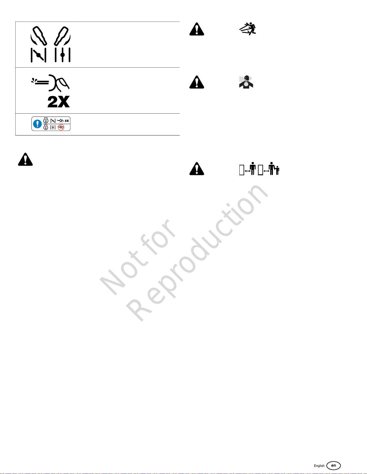
M Choke CLOSED / Choke OPEN
N Primer Button
O Alternate Choke-Prime Instructions
Operation
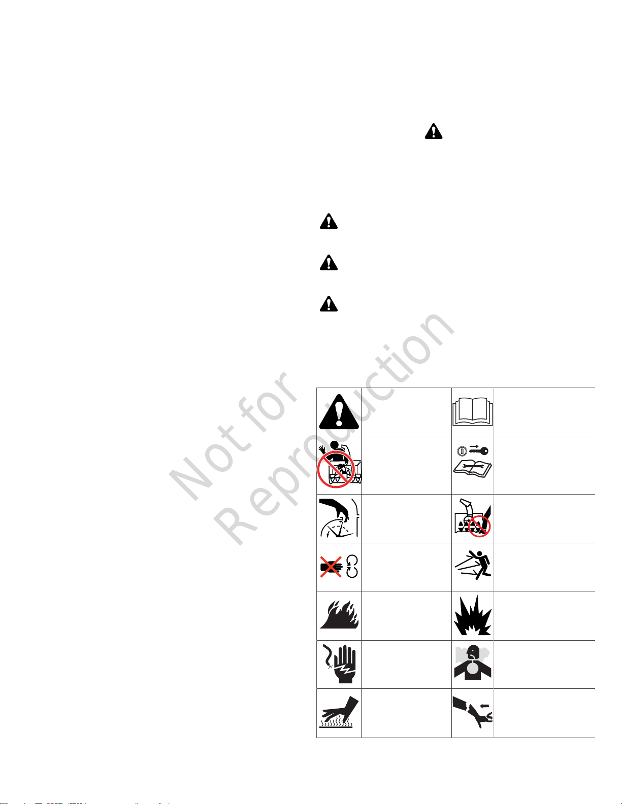
WARNING
This snowthrower is only as safe as the operator. If it is
misused, or not maintained correctly, it can be dangerous.
Remember you are responsible for your safety and those
around you.
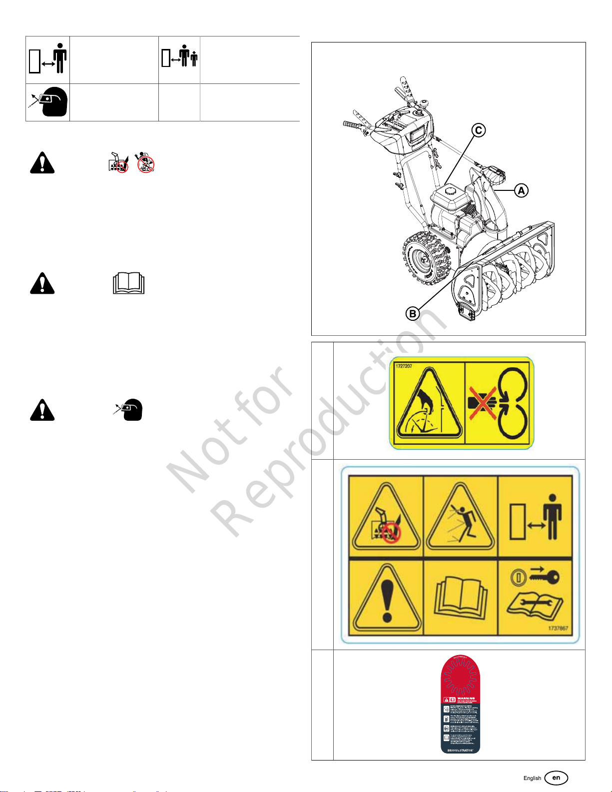
• When leaving the operating position always disengage
the auger, STOP the engine, and remove the key. DO
NOT leave a running machine unattended.
• DO NOT operate the snowthrower without the correct
guards, and other safety protective devices in place and
working.
• Be careful when you operate the unit on gravel
driveways, walkways, or roads. Stay alert for hidden
hazards or traffic.
• DO NOToperate the snowthrower without good
visibility or light. Always be sure of your footing, and
keep a firm hold on the handles. Walk; never run.
• Be careful to avoid slipping or falling, especially when
you operate the snowthrower in reverse.
• Be careful when you operate the snowthrower on
slopes.
• If you strike a foreign object, stop the engine, remove
the wire from the spark plug, thoroughly inspect the
snowthrower for damage, and repair the damage before
you start and operate the snowthrower.
• DO NOT operate the equipment without wearing
adequate winter garments. Avoid loose fitting clothing
that can get caught in moving parts. Wear footwear that
will improve footing on slippery surfaces.
• DO NOT touch a hot muffler or engine. Let the muffler
and engine cylinder to cool before touching.
Operating Area
1. Identify the walkways and driveways where you plan to
operate the snowthrower.
2. Make sure that the area is free of debris or objects that
the auger could pick-up and throw from the chute.
WARNING
This machine is capable of throwing objects that could
injure bystanders or cause damage to buildings.
3. Before you start the engine, move the snowthrower
outdoors and away from windows and doors.
WARNING
Engines give off carbon monoxide, an ordorless, colorless,
poison gas. Breathing carbon monoxide can cause nausea,
fainting, or death.
• Start and operate the engine outdoors.
• Do not operatethe engine in an enclosed area, even
if doors or windows are open.
4. Make sure that the operating area is clear of bystanders,
especially children.
WARNING
This snowthrower is capable of amputating hands and feet,
and throwing objects. Read and obey the safety instructions
in this manual. Failure to do so could result in death or
serious injury.
• Keep children out of the area during operation.
• Children are often attracted to the equipment. Be
mindful of all persons present.
• Be alert and turn the unit off if bystanders enter the
area.
• Use extra care when you approach blind corners,
shrubs, trees, or other objects that can obscure vision.
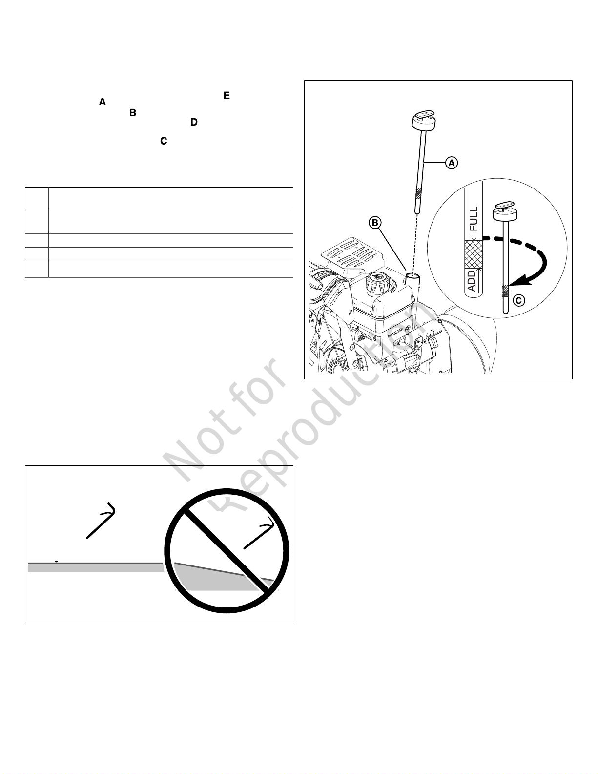
Engine
Oil Recommendations
Oil Capacity:See theSpecificationssection.
NOTICE
This engine was shipped from Briggs & Stratton without oil.
Equipment manufacturers or dealers may have added oil
to the engine. Before you start the engine for the first time,
make sure to check the oil level and add oil as specified
by the instructions in this manual. If you start the engine
without oil, it will be damaged beyond repair and will not be
covered under warranty.
We recommend the use of Briggs & Stratton®Warranty
Certified oils for best performance. Other high-quality
detergent oils are permitted if classified for service SF, SG,
SH, SJ or higher. Do not use special additives.
Outdoor temperatures determine the correct oil viscosity
for the engine. Use the chart to select the best viscosity
for the outdoor temperature range expected. Engines on
most outdoor power equipment operate well with 5W-30
Synthetic oil. For equipment operated in hot temperatures,
Vanguard®15W-50 Synthetic oil gives the best protection.