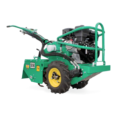
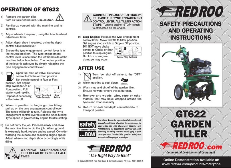
red roo GT622 Use and care manual

GT622
GARDEN TILLER
Commercial Environmental Equipment
Operation, Safety & Maintenance Instructions
™
GT622
Commercial Environmental Equipment
GT622
Commercial Environmental Equipment
Online Demonstration Available at: www.redroo.com/products/rotaryhoe

2
INTRODUCTION
Dear Valued Customer,
Congratulations! You are now the proud owner of the Red Roo Model GT622
Garden Tiller. Please take a moment of your time to look over the following
method of operation. Pay particular attention to the safety and operating
information Familiarise yourself with the tiller, its characteristics and
instructions.
If you have any questions or need any replacement parts in the future please
contact us at your convenience on our toll-free phone number 1300 133 767
or redroo.com
THANK YOU for your patronage, confidence and support in
Red Roo commercial environmental equipment.
™
1301-0068-A © Copyright 2012
Red Roo Sales & Service Company Pty. Ltd.
Red Roo Customer number
Machine Identification Record
Machine model number ________________________
Machine serial number
Engine manufacturer
Engine model number
Engine serial number

3
™
Table of Contents
41-43 Keysborough Avenue, Keysborough, Victoria, Australia 3173
Tel.: +61 (03) 9769 0455 Fax: +61 (03) 9769 0366
Outside Melbourne Metro: Tel.: 1300 133 767 Fax: 1300 133 757
redroo.com
RED ROO SALES & SERVICE COMPANY PTY. LTD.
ASSSEMBLY INSTRUCTIONS 3
ABOUT THIS MANUAL 4
SAFETY INSTRUCTIONS 5
OPERATING INSTRUCTIONS 6
SERVICE INFORMATION 7
HOUR METER
HONDA GX160 SCHEMATIC
ROBIN EX17 SCHEMATIC
HYDRAULIC SCHEMATIC
7
8
9
8
TROUBLESHOOTING
11
SPECIFICATIONS 10
ENGINE CONTROLS
12
WORKSITE ASSESSMENT 13
14
GT622 ASSEMBLY ILLUSTRATIONS
RED ROO WARRANTY 18
ASSEMBLY
INSTRUCTIONS
1. Remove the tiller from shipping crate. Please inspect immediately for any damage and
notify the shipping company and Red Roo, right away if any is found.
2. Check reservoir according to instructions in service information on the following page.
3. Fill the engine with fuel and oil according to the engine manual.
4. When documentation refers to “right side” or “left side”, it is relative to the operator’s
position with both hands on the handlebars.

SAFETY FIRST – Stay Alert, Do Not Get Hurt
Read this section before use!
The GT622 Garden Tiller is designed to cultivate soiland therefore is potentially
dangerous. Careless or improper use may result in serious or even fatal injury.
It is important that you read and understand the contents of this manual and that you allow only
mature, adult individuals to operate your Garden Tiller. It is your responsibility to ensure that any
individual who operates your garden tiller has read and understood this manual.
Never use the garden tiller for any other purpose than soil cultivation. The machine is designed for
this purpose only. Any other use may result in serious or even fatal injury and/or damage to the
machine.
ABOUT THIS MANUAL
The information contained in this manual has been prepared to assist you in the safe operation, the
routine maintenance and general care of your Red Roo product. By following these guidelines, you
may look forward to years of reliable service from your Red Roo. Information is catergorised and
denoted by the following symbols and phrases:
SAFETY FIRST Identifies general safety practices.
DANGER! An instruction which, if not followed, could result in serious or fatal injury.
WARNING! An instruction which, if not followed, could result in personal injury.
CAUTION! An instruction which, if not followed, could damage machine components.
4
HAZARD SYMBOLS & MEANINGS
Before operatingthisMachine read
andobserve all Warnings, Cautions
andInstructions on theMachineand
in theOperatorsManual. Although the
reading of information contained in
thismanualdoesnoteliminatethe
risk involved in operatingthis
machine,yourunderstanding of this
information will promotethe correct
andsafeuse of yourmachine.Failure
to followInstructionsandSafety
Informationcould result in serious
injury or death.
Read Hearing
Protection
Eye
Protection
Wear
Gloves
Cut Hand
No
Bystanders
Don’t Remove
Guards
Moving
Parts
Hot
Surfaces
Don’t Refuel
Hot Engine
Keep Clear
Rotating Tynes
Explosion
Electrical
Shock
Toxic
Fumes
Remove Spark
Plug Leads

USE COMMON SENSE AND PLENTY OF IT
1) DO NOT allowanyperson to operate the garden tillerwithout first readingandunderstanding the
safety precautionsandoperatinginstructions. Readandunderstand the engine manual.KNOW
THE CONTROLS AND HOW TO STOP THE GARDEN TILLERQUICKLY IN ANEMERGENCY.
2) NEVER allow children or untrained adults to operate the garden tiller.
3) ALWAYSwearprotectiveclothingwhenoperating the garden tiller.
This includes, but is not limited to: safety glasses, loose fitting gloves,
steel capped boots and hearing protection. NEVER wear loose fitting
clothing or jewellery when operating the garden tiller. Keep all clothing away from moving parts. Items
could become caught in the machine, resulting in injury.
4) ALWAYS operate the garden tiller in a well lighted area.
5) ALWAYSmakecertain that the tyne engagement control lever is in the “neutral”positionprior to
starting the engine. The TYNE ENGAGEMENT CONTROL LEVER on the left handlebar is for the
6) ALWAYS operate garden tilleronlevel groundonly. Police the areabeforegarden tilling.
Remove any foreignobjects in the diggingarea(egbricks,rocks,wireandsticks). Locate
andmarkany sprinklerheads, water pipes, gaslines, electrical and telephone cables or
any other hazard either below or above ground.
7) DO NOT allow otherpersonsnear the garden tiller. It is the responsibility of the operator to keep
bystanders and animals a minimum of 6 metres (18ft) away from the machine while it is in operation.
9) NEVERoperate the garden tillerwhen fatigued.ALWAYS BE ALERT! If youbecome tiredwhile
operating the garden tiller, take a break. If youhaveanyphysical or mental condition thatmay be
aggravated by strenuous work, consult your physician before you operate this equipment.
NEVER operate the garden tiller under the influence of medication, alcohol or drugs.
10) ALWAYSKEEP YOUR HANDS, FEETAND BODY AWAY FROM THE DIGGING
AREA WHILE ENGINE IS RUNNING.
11) NEVER operate the unit without the safety guards in place and in working order.
Keep the unit well maintained and in good working order
12) DO NOT leave the machine unattended while the engine is running.
13) DO NOT overspeed the engine or alter the governor settings. Excessive speed is dangerous and will
shorten engine life.
14) NEVERoperate the garden tiller in an enclosedarea.Engineexhaustcontainscarbon
monoxide, an odourless and tasteless poison.
15) STOP the engine, disconnect the spark plug lead and allow engine to cool before inspecting or
performing maintenance on the garden tiller.
16) REFUELLING
*SHUT OFF ENGINE. DO NOT REFUEL AN ENGINE WHILE OPERATING!
* Allow engine to cool. Minimum 5 minutes.
*USE UNLEADED FUEL ONLY. Use clean, fresh unleaded fuel.
*Do not mix oil with unleaded fuel.
* Do not over-fill fuel tank. Allow space for fuel expansion.
* Do not smoke near equipment.
* Allow no naked flame or hot material in refuelling area.
* Use only approved fuel containers and funnels. Remember, fuel is a potential hazard.
* Refer to engine owners manual for full details.
SAFETY PRECAUTIONS FOR GT622 USERS
Outdoor Power Equipment Institute Recommendations
WARNING TO PURCHASERS OF INTERNAL COMBUSTION
ENGINE EQUIPPED MACHINERY OR DEVICES:
The equipmentwhich you have purchased doesnothave a spark arrester muffler. If thisequipment
is to be used on any forest and brush covered land or grass covered unimproved land, the law may
require that a sparkarrester muffler be installedand be in effectiveworkingorder. The spark
arrester must be attached tothe exhaust system and comply with local authorities by-laws.
5
Hydraulic oil is under extreme pressure and can get under skin and burn or poison. Check for
leaks with cardboard.
8)
operator’s protection. All motion stops when the control lever’s released!
DO NOT TAPE THE CONTROL LEVER UP or otherwise by-pass this safety feature!

OPERATING INSTRUCTIONS - GT622
BEFORE USE
1) Ensure that all grass and weeds have been cut as low as possible.
2) If the garden tiller is to be used in clay or hard ground conditions, it is recommended to water the area
thoroughly and allow sufficient time for the soil to soften.
3) Police the area. Remove any foreign objects from the area.
4) Identify and mark the location of sprinkler heads, gas pipes, telephone cables, etc.
OPERATION
2) Familiarize yourself with the machine and its controls.
6) Open fuel shut-off valve. Set choke control to Choke or Start position.
Set throttle control to Run or Fast position. Set engine stop switch to
On or Run position. Pull starter cord rapidly. Repeat (if necessary) with
choke off.
WARNING! –KEEP HANDS AND FEET CLEAR OF TYNES AT ALL TIMES!
WARNING!–IN CASE OF DIFFICULTY,RELEASE THE TYNE ENGAGEMENT CONTROL LEVER
ALLTILLING ACTIONSTOPS.Turn the engine "STOP" switich to off located on the engine.
9) Stop Engine: Release the safety clutch controllever.Move throttle to Slowposition.
Set enginestop switch to Stop or Offposition.DO NOT move choke controltoChoke
or Start position tostop engine. Backfire or engine damage may occur.
AFTER USE
1) Turn fuel shut off valve to the "OFF" position.
2) Allow machine to cool down.
3) Wash mud and dirt off of the garden tiller.
Ensure no water enters the carburettor.
4) Remove any weeds, wire, rope or other material that may have wrapped around the tynes and rotor
assembly.
5) Return wheel axle to forward position for transport. Replace shaft locking collar.
6) Return depth shoe (if equipped) to full Up position.
6
1) Remove the garden tiller
from its trailer/carrier/ute.Use caution.
5) Ensure the tyne engagement control lever is in the neutral position. The tyne engagement control lever is
located on the left hand side of the machine below handle bar. The neutral position of the lever is achieved by
simply releasing the tyne engagement control lever.
4)
3) Adjust wheels if required, using the handle wheel adjustment lever.
Adjust depth shoe if required, using the depth control adjustment lever.
begin to turn, adjust accordingly in the rear position while tilling. Release the tyne engagement control
lever to stop the tynes turning. Tyne speed is governed by engine throttle setting.
7) Wheninposition to begingarden tilling, pull up on the tyne engagement control lever.The tynes will
8) Do not hurry the job. Proceed slowly and allow the machine time to do the job. When ground is extremly
hard, reduce engine speed. Consider watering the surface and reducing engine speed. Adjust wheels and
depth shoe accordingly while tilling.
6

622GT Owner’s/Operator’s Manual 8/28/12 Page 4 of 17
HOUR METER
The SenDEC®TACH/HOUR hour meter tracks the hours of machine operation in order for
routine maintenance to be performed on a timely basis.
Your SenDEC® hour meter is pre-set at the SenDEC® factory to go into Flash Alert mode at 25-
hour intervals. Although the engine manufacturer does not require changing engine oil this often,
due to heavy-duty use and extreme conditions inherent to tiller use, Red Roo
recommends frequent oil changes
strongly
.
Refer to this manual for equipment service requirements and to the Engine Manual for engine
service requirements.
While Flash Alert is active, hold the tip of the RESET TOOL (Key Cancel Wand) against the
meter as shown. Within several seconds, the display will stop flashing indicating the Service
Interval has been reset. If the wand gets lost, a small mechanic’s pick-up magnet will work.
RESET TOOL
SERVICE
INFORMATION
1. Check the reservoir level using the sight glass on the top of the tank. If required, add to
reservoir with tractor transmission hydraulic oil (AW or ISO rating of 68 is recommended ).
Recheck oil level after the tiller has been run and oil has been circulated through the tine
motor. Routinely check level thereafter. DO NOT OVERFILL THE TANK.
2. Change the hydraulic oil filterafter the first 50 hours of use. Change it after every 200 hours
thereafter.
3. Check the tine bolts after each use and tighten as needed. Check all hydraulic fittings for
leaks and tighten if necessary.
4. Tines should be changed as often as needed for the machine to do a satisfactory and efficient
tilling job. Use Loctitestud and bearing adhesive/sealant on tine bolt threads to prevent
loosening.
5. The grease zerk on the end of the tine frame should be greased after every 4 to 8 hours of
use.
6. The grease zerks on the wheels should be greased monthly.
IMPORTANT: The engine is normally serviced prior to shipping. However, shipping
regulations may prohibit this. Check levels and add oil and fuel as required before starting.
Service according to the engine manual before starting.
WARNING: Running the tiller without hydraulic oil will cause serious damageto the hydraulic
pump. CHECK RESERVOIR LEVEL BEFORE STARTING THE MACHINE.
RED ROO EQUIPMENT WARRANTY
Red Roo warrants all Red Roo equipment to be free of defects in material and workmanship for
a period of one (1) year dating from delivery to the original user.
This Warranty is in lieu of all other warranties, whether written or implied, and is limited to:
1. Replacement of parts returned to the dealer and/or factory and determined defective upon
inspection. (Replacement for parts to dealers shall be at dealer cost plus shipping
charges.)
2. Time for pick-up and/or delivery, transportation or service calls by dealers is excluded.
Manufacturer reserves the right to determine reasonable time required for repair.
Warranty does not apply to damage caused by abuse or neglect. Time and materials required for
normal maintenance and service are also excluded from warranty coverage.
Engines, engine accessories and tires are warranted by the original manufacturers and are not
covered by the Red Roo Warranty. Wear parts such as tiller tines, sprockets, trencher
teeth, bearings, etc. are also excluded unless it can be determined that a defect has contributed to
premature wear.
622GT Owner’s/Operator’s Manual 8/28/12 Page 4 of 17
HOUR METER
The SenDEC®TACH/HOUR hour meter tracks the hours of machine operation in order for
routine maintenance to be performed on a timely basis.
Your SenDEC® hour meter is pre-set at the SenDEC® factory to go into Flash Alert mode at 25-
hour intervals. Although the engine manufacturer does not require changing engine oil this often,
due to heavy-duty use and extreme conditions inherent to tiller use, Red Roo
recommends frequent oil changes
strongly
.
Refer to this manual for equipment service requirements and to the Engine Manual for engine
service requirements.
While Flash Alert is active, hold the tip of the RESET TOOL (Key Cancel Wand) against the
meter as shown. Within several seconds, the display will stop flashing indicating the Service
Interval has been reset. If the wand gets lost, a small mechanic’s pick-up magnet will work.
RESET TOOL
7

PUMP
4cc
.24 ci
MOTOR
125cc
4.9 ci
DWG# HYD-SCHEMATIC
TITLE:
SHEET 1 OF 1
HYDRAULIC SCHEMATIC
SCALE: 1:3
PRODUCT LINE: 622 GT DATE: 8/12
PUMP
4cc
.24 ci
MOTOR
125cc
4.9 ci
DWG# HYD-SCHEMATIC
TITLE:
SHEET 1 OF 1
HYDRAULIC SCHEMATIC
SCALE: 1:3
PRODUCT LINE: 622 GT DATE: 8/12
Commercial Environmental Equipment
™
622GT Owner’s/Operator’s Manual 8/28/12 Page 5 of 17
ELECTRICAL SCHEMATIC - HONDA GX160
622GT Owner’s/Operator’s Manual 8/28/12 Page 5 of 17
ELECTRICAL SCHEMATIC - HONDA GX160
622GT Owner’s/Operator’s Manual 8/28/12 Page 5 of 17
ELECTRICAL SCHEMATIC - HONDA GX160
8
PUMP
4cc
.24 ci
MOTOR
125cc
4.9 ci
DWG# HYD-SCHEMATIC
TITLE:
SHEET 1 OF 1
HYDRAULIC SCHEMATIC
SCALE: 1:3
PRODUCT LINE: 622 GT DATE: 8/12

622GT Owner’s/Operator’s Manual 8/28/12 Page 6 of 17
ELECTRICAL SCHEMATIC - ROBIN EX17D
9

622GT Owner’s/Operator’s Manual
8/28/12
Page8 of 17
GT622 SPECIFICATIONS
MODEL NUMBER 622GT
DIMENSIONS
Weight 211lbs. (95.71kg)
Height 50” (1.27m)
Length 59” (1.5m)
Width 28” (71.12cm)
ENGINE
Engine Honda GX160
Optional engine Robin EX 17D
FUEL Gasoline
POWER: hp (kW) at 3600 RPM H-5.5 hp (4.0kW)
POWER: hp (kW) at 4000 RPM R-5.7 hp (4.2kW)
FUEL CAPACIT Y H-0.95 U.S. gallons (3.6 liters)
R-0.94 U.S. gallons (3.6 liters)
ENGINE OIL CAPACITY H-.63 quart (.60 liters)
R-.63 quart (.60 liters)
HOUR METERStandard
HYDRAULIC SYSTEM
Reservoir Capacity 1.4 U.S. gallons (5.3liters)
Oil Cooler Standard
Hydraulic pump output 4 gpm (15.14 liters)
10

622GT Owner’s/Operator’s Manual 8/28/12 Page 11 of 17
ENGINE CONTROLS
CHOKE: Use to aid starting the engine when it is cold.
IGNITION SWITCH: There are two ignition switches. One switch is located on the control panel
for your convenience. The other is located on the engine. Use these to start and stop the engine.
THROTTLE: Use this to adjust engine speed.
GAS SHUT-OFF: Use this when starting or stopping machine.
GAS SHUTOFF THROTTLE
CHOKE IGNITION
GAS SHUT-OFF THROTTLE
11

622GT Owner’s/Operator’s Manual 8/28/12 Page 9 of 17
622GT TILLER TROUBLE SHOOTING GUIDE
CAUTION: ALW AYS USE EXTREME CARE WHEN TROUBLE SHOOTING OR MAKING
ADJUSTMENTS ON THE TILLER. STAY CLEAR OF TYNES WHEN ENGINE IS
RUNNING. ALWAYS SHUT THE ENGINE OFF BEFORE DISASSEMBLING ANY
COMPONENT.
A. ENTIRE HYDRAULIC SYSTEM DOESNOT OPERATE AND THE ENGINE IS NOT UNDER LOAD
1. Lowhydraulicoil in tank.
2. Hydraulic pump-to -engine coupler has
slipped.
Fill to center of sight glass.
Check for wear and replace both coupler
halves and rubber spider as needed.
B. TYNES FAIL TO ROTATE
1. Tyne motor worn. Rebuild or replace motor. New motors are
available from Red Roo.
C. ENGINE LUGS DOWN OR DIES AND TINES DO NOT TURN.
1. Rocks or other obstruction blocking tines.
2. Tyne shaft bound with wire, vines, or
grass.
3. Outboard tine shaft bearings binding.
4. Engine improperly tuned or maintained.
5. Low oil alert causes engine to shut down.
6. Engine losing power due to wear.
D. OIL LEAKS IN HYDRAULIC SYSTEM.
1. Fittings are loose.
2. Worn or broken hoses.
Shut OFF engine and remove obstructionor
reverse tynes.
Shut OFF engine and remove debris,
especially at theends.
Lubricate or replace bearings as needed.
See engine manual and correct as needed.
This may occur if tilling on hills,(not
advised). Level the tiller and check engine oil
level. Fill if required.Oil alert should reset.
See engine manual.
See engine manual.
Tighten as required.
Replace as necessary.
12
622GT Owner’s/Operator’s Manual
8/28/12
Page10 of 17
TROUBLE SHOOTING GUIDE (continued)
E. EXCESSIVE FOAMING OFHYDRAULIC OIL FROM VENT HOSE.
1. Improper oil used.
2. Pump sucking air.
Verify that hydraulic oil used has anti-
foaming additives.
Inspect and tighten fittings on intake side of
pump.
OPERATING INSTRUCTIONS
1. READ SAFETY
INSTRUCTIONS
BEFORE
O
PER
A
T
I
N
G
!
2. Be sure engine oil and hydraulic oil are at proper levels before starting the tiller.
3. STUDYAND UNDERSTAND
CONTROLS
BEFORE BEGINNING
O
PER
A
T
I
O
N!
4. OPERATE TILL ER ON LEVEL GROUND ONLY!
5. VALVE LEVER activates tines when squeezed. Tines stop when the leveris released.
6. CAUTION!! Tines reverse at a reduced speed when the VALVE LEVER is pushed
forward.This should ONLY be done to dislodge an obstruction or back out of a corner.
7. Adjust handlebar to a comfortable position.
8. Wheels and drag bar can be adjusted to control speed and tilling depth.
622GT Owner’s/Operator’s Manual 8/28/12 Page 9 of 17
622GT TILLER TROUBLE SHOOTING GUIDE
CAUTION: ALW AYS USE EXTREME CARE WHEN TROUBLE SHOOTING OR MAKING
ADJUSTMENTS ON THE TILLER. STAY CLEAR OF TYNES WHEN ENGINE IS
RUNNING. ALWAYS SHUT THE ENGINE OFF BEFORE DISASSEMBLING ANY
COMPONENT.
A. ENTIRE HYDRAULIC SYSTEM DOESNOT OPERATE AND THE ENGINE IS NOT UNDER LOAD
1. Lowhydraulicoil in tank.
2. Hydraulic pump-to -engine coupler has
slipped.
Fill to center of sight glass.
Check for wear and replace both coupler
halves and rubber spider as needed.
B. TYNES FAIL TO ROTATE
1. Tyne motor worn. Rebuild or replace motor. New motors are
available from Red Roo.
C. ENGINE LUGS DOWN OR DIES AND TINES DO NOT TURN.
1. Rocks or other obstruction blocking tines.
2. Tyne shaft bound with wire, vines, or
grass.
3. Outboard tine shaft bearings binding.
4. Engine improperly tuned or maintained.
5. Low oil alert causes engine to shut down.
6. Engine losing power due to wear.
D. OIL LEAKS IN HYDRAULIC SYSTEM.
1. Fittings are loose.
2. Worn or broken hoses.
Shut OFF engine and remove obstructionor
reverse tynes.
Shut OFF engine and remove debris,
especially at theends.
Lubricate or replace bearings as needed.
See engine manual and correct as needed.
This may occur if tilling on hills,(not
advised). Level the tiller and check engine oil
level. Fill if required.Oil alert should reset.
See engine manual.
See engine manual.
Tighten as required.
Replace as necessary.

622GT Owner’s/Operator’s Manual
8/28/12
Page16 of 17
WORK SITE ASSESSMENT
Examine the work area for any conditions or obstructions that may inhibit tilling or create a safety
hazard for the operator or others. Use the information in this manual combined with good
judgment to identify any hazards to avoid.
In addition to calling to DETERMINE LOCATION OF UNDERGROUND UTILITIES (see
previous section for details), the operator and/or job foreman should visually inspect the work site.
Look for electrical drop boxes, notices of underground placements, manhole covers, recent
trenching or tilling activity, any evidence of possible underground placements, banks, drop-offs,
rocks, wire, uneven terrain, any existing holes and toxic ground conditions.
Only operate tiller outdoors and avoid breathing engine exhaust and fumes.
WARNING : Engine exhaust contains carbon monoxide gas that is toxic. Breathing it can
cause unconsciousness and death.
Do not operate tiller near any source of flammable dust or vapors.
WARNING : Sparks from the engine exhaust can cause an explosion or fire in a flammable
or explosive atmosphere. Fuel fumes can catch fire or explode.
Allow adequate side and overhead clearances between tiller and any objects such as
buildings, fences, and trees.
Adequate lighting is required, daylight or artificial, for safe operation of the tiller.
Keep others away. If the job site is near a road or pedestrian path, warn and divert both
motorized traffic and pedestrians. As appropriate, erect barriers, use traffic flag personnel,
signs, cones, and lighting devices to insure safety.
WARNING : Someone could step into the tilled area by accident. Walking near the edge of
the tilled area could cause loss of balance and possibly cause someone to fall into the
rotating tynes. Contact with the rotating tynes while in operation will cause serious injury or
even death.
MACHINE FUNCTION CHECK:If the operator releases the TYNE ENGAGEMENT CONTROL LEVER,
the rotating tynes should stop. This is intended for your safety and must be maintained in good
functional condition. Contact your dealer or the factory if anything on the tiller does not function properly.
13
GT622
GARDEN TILLER
Commercial Environmental Equipment
Operation, Safety & Maintenance Instructions
™
622GT Owner’s/Operator’s Manual
8/28/12
Page16 of 17
WORK SITE ASSESSMENT
Examine the work area for any conditions or obstructions that may inhibit tilling or create a safety
hazard for the operator or others. Use the information in this manual combined with good
judgment to identify any hazards to avoid.
In addition to calling to DETERMINE LOCATION OF UNDERGROUND UTILITIES (see
previous section for details), the operator and/or job foreman should visually inspect the work site.
Look for electrical drop boxes, notices of underground placements, manhole covers, recent
trenching or tilling activity, any evidence of possible underground placements, banks, drop-offs,
rocks, wire, uneven terrain, any existing holes and toxic ground conditions.
Only operate tiller outdoors and avoid breathing engine exhaust and fumes.
WARNING : Engine exhaust contains carbon monoxide gas that is toxic. Breathing it can
cause unconsciousness and death.
Do not operate tiller near any source of flammable dust or vapors.
WARNING : Sparks from the engine exhaust can cause an explosion or fire in a flammable
or explosive atmosphere. Fuel fumes can catch fire or explode.
Allow adequate side and overhead clearances between tiller and any objects such as
buildings, fences, and trees.
Adequate lighting is required, daylight or artificial, for safe operation of the tiller.
Keep others away. If the job site is near a road or pedestrian path, warn and divert both
motorized traffic and pedestrians. As appropriate, erect barriers, use traffic flag personnel,
signs, cones, and lighting devices to insure safety.
WARNING : Someone could step into the tilled area by accident. Walking near the edge of
the tilled area could cause loss of balance and possibly cause someone to fall into the
rotating tynes. Contact with the rotating tynes while in operation will cause serious injury or
even death.
MACHINE FUNCTION CHECK:If the operator releases the TYNE ENGAGEMENT CONTROL LEVER,
the rotating tynes should stop. This is intended for your safety and must be maintained in good
functional condition. Contact your dealer or the factory if anything on the tiller does not function properly.

ENGINE ASSEMBLY
DWG# 00486-H
SCALE: 1:4
PRODUCT LINE: GARDEN TILLER
SHEET 1 OF 1
TITLE:
DATE: 10-11
78
9
7
5
11
12
4
7
10
6
7
32
10
13
1
4cc
ITEM NO. QTY. PART NO. DESCRIPTION
1 1 07011 ENGINE, 5.5 HP HONDA GX160
2 1 11002 JAW COUPLER, 3/4" BORE, L075
3 1 11996 SPIDER, URATHANE, L075
4 1 11003 JAW COUPLER, 1/2" BORE, L075
5 1 11147 PUMP, SNP1
6 1 12198 PUMP ADAPTER
7 12 05068 WASHER, 5/16 SAE ZINC
8 4 05052 HH CAP SCREW, 5/16-24 NF X 3/4 G5 ZINC
9 2 05297 HH CAP SCREW, 5/16-18 NC X 1-1-4 G5 ZINC
10 6 05273 NUT, NYLOCK, 5/16-18 NC ZINC
11 1 10404 FITTING, 6801-6-8
12 1 04523 FITTING, 4601-12-10
13 4 05294 HH CAP SCREW, 5/16-18 NC X 1-1/2 G5 ZINC
ENGINE OPTIONS:
HONDA GX160, PN 07011
SUBARU / ROBIN, PN 07013
Commercial Environmental Equipment
™
SHEET 1 OF 1
TINE FRAME ASSEMBLY, 22"
00485-22
DWG#
PRODUCT LINE: GARDEN TILLER
SCALE: 1:8
TITLE:
DATE: 10-11
ITEM NO. QTY. PART NO. DESCRIPTION
1 1 12191 TINE DRIVER
2 16 05061 HH CAP SCREW, 7/16-20 NF X 1 G8 ZINC
3 8 05063 HH CAP SCREW, 7/16-20 NF X 1-1/4 G8 ZINC
4 1 12209 SAUER 125cc
5 1 12192 DIRT SHIELD
6 1 12194 SHAFT SPACER
7 1 10144 OUTBOARD BEARING ASSEMBLY
8 12 03196 TINE, REVERSIBLE
9 1 12195-22 TINE FRAME, 22"
10 4 05057 HH CAP SCREW, 3/8-16 NC X 3/4 G5 ZINC
11 24 05074 NUT, 7/16-20 NF G8 ZINC
12 6 05131 HH FLANGE SCREW, 5/16-18 NC X 3/4 G8 ZINC
13 6 05273 NUT, NYLOCK, 5/16-18 NC ZINC
14 1 05044 GREASE ZERK, 1/4-28 UNF
ITEM NO. QTY. PART NO. DESCRIPTION
15 1 12206-22 TINE SHAFT, 22"
16 2 10800 HYDRAULIC FITTING, 6400-0-6-10
17 1 05083 WASHER, 7/16 USS ZINC
18 1 05103 WASHER, 3/8 A325 HARDENED ZINC
19 1 05059 HH CAP SCREW, 3/8-16 NC X 1 G5 ZINC
20 2 12189 SPACER RING
21 1 12234 MOTOR GUARD
22 3 05169 WHIZ LOCK, 5/16-18 NC X 1/2 ZINC
23 1 03040-04 DECAL, "GREASE DAILY"
11
21
23
13
14
19
18
17
12
4
16
6
1
10
520
2
8
11
7
15
3
9
22
TIGHTEN MOTOR
NUT TO 75 FT-LB
Commercial Environmental Equipment
™
14

ITEM NO. QTY. PART NO. DESCRIPTION
1 1 12202 HANDLEBAR
2 1 11287 ROQUET VALVE, 6102-TIPOS
3 1 12203 VALVE ROCKER
4 1 12210 FULCRUM
5 1 12204 VALVE LEVER
6 5 05273 NUT, NYLOCK, 5/16-18 NC ZINC
7 1 03017 MASTER LINK, #50 CHAIN
8 4 12235 BEARING
9 9 05081 WASHER, 1/4 SAE ZINC
10 4 05237 HH CAP SCREW, 1/4-20 NC X 1 G5 ZINC
11 4 05096 NUT, NYLOCK, 1/4-20 NC ZINC
12 1 05038 RUE RING COTTER #8
13 2 03032-01 GRIP, 1 X 5 (P/N 03032 IS A PAIR)
14 1 06420 ROCKER SWITCH, IGNITION OFF/ON
15 1 06421 GROUND WIRE, IGNITION SWITCH
16 1 03806 QUICK-SPLICE
17 2 05068 WASHER, 5/16 SAE ZINC
18 2 05568 HH CAP SCREW, 5/16-18 NC X 2-1/2 G5 ZINC
19 2 10404 FITTING, 6801-6-8
20 2 04538 FITTING, 6801-6-6
21 1 12342 ADJUST LEVER
22 1 10599 HH CAP SCREW, 3/8-16 NC X 4-1/2 G5 ZINC
23 1 05073 NUT, NYLOCK, 3/8-16 NC ZINC
24 1 05269 NUT, 3/8-16 NC GRB ZINC
25 3 05351 SH SHOULDER SCREW, 3/8 X 1/4
26 1 03066 SPRING, CENTURY S774
27 2 05101 WASHER, 3/8 SAE ZINC
28 1 03018 GRIP, 1/8 X 3/4 X 2-3/4
29 1 04406-01 TINE DECAL
30 1 03341-07 DECAL, "IGNITION OFF/ON"
31 2 07007-11 HH FLANGE SCREW, 6mm-1.0 X 12mm ZINC
32 1 03093 GRIP, .625 X 4.5
CONTROL ASSEMBLY
DWG# 00488
SCALE: 1:6
PRODUCT LINE: GARDEN TILLER
SHEET 1 OF 2
TITLE:
DATE:3-12
Commercial Environmental Equipment
™
15
TITLE: TILLER COMPLETE ASSEMBLY
DWG# 00487
SCALE: 1:12
PRODUCT LINE: GARDEN TILLER
SHEET 1 OF 1
DATE: 10-11
SCALE 1 : 6
DETAIL A
18
15 16
13
14
17
4
61 7
19 3
2
10
12
13
9
8
11
18
5
A
ITEM NO. QTY. PART NO. DESCRIPTION
1 1 00486 ENGINE ASSEMBLY
2 1 00485-22 TINE ASSEMBLY, 22"
3 1 00493 FRAME ASSEMBLY
4 1 00488 CONTROL ASSEMBLY
5 1 00489 WHEEL ASSEMBLY
6 1 11987 BREATHER HOSE ASSY
7 1 04555 FITTING, 6801-4-4
8 1 12214 HOSE, SUCTION 3/4"
9 2 05008 CLAMP, 1" HOSE, CTB-29
10 1 12360 TUBE CLAMP, 3/4", 265-024
11 1 12213 HOSE, PUMP / VALVE, 3/8"
12 1 12216 HOSE, VALVE FR / MOTOR FR, 3/8"
13 1 12215 HOSE, VALVE REAR / CHECK
14 1 12242 CHECK VALVE BODY
15 1 12243 ORIFICE PLUG
16 1 10401 FITTING, 6400-6-6
17 1 04226 FITTING, 6400-6-8
18 1 12245 HOSE, MOTOR RETURN / CHECK
19 1 12205 HOSE 3/8". VALVE / FILTER
Commercial Environmental Equipment
™

SHEET 1 OF 1
WHEEL ASSEMBLY
00489
DWG#
PRODUCT LINE: GARDEN TILLER
SCALE: 1:6
TITLE:
DATE: 8-12
75
16
19
3
6
13
9
14
4
6
18
8
12
11
15
10
2
1
17
ITEM NO. QTY. PART NODESCRIPTION
1 1 11745 SWING ARM
2 1 11747 RAISE LINK
3 1 11746L LIFT LEVER
4 1 10257 HH CAP SCREW, 1/2-20 NF X 1-3/4 G5 ZINC
5 1 11113 CUSHION
6 2 05102 WASHER, 1/2 SAE ZINC HARDENED
7 1 03200 THRUST WASHER, .75 X 1 X .060, HARD
8 1 05075 NUT, NYLOCK, 1/2-20 NF ZINC
9 2 10276 HH CAP SCREW, 1/2-13 NC X 6 G5 ZINC
10 2 05073 NUT, NYLOCK, 3/8-16 NC ZINC
11 2 05098 NUT, NYLOCK, 1/2-13 NC ZINC
12 2 11056 NUT, JAM, 1/2-13 NC G5 ZINC
13 2 05101 WASHER, 3/8 SAE ZINC
14 2 05222 COTTER PIN 1/8 X 3/4
15 2 05183 BH SHOULDER SCREW, 1/2D X 3/4L
16 1 12151 TUBE CAP, 1.0 X 7/8
17 2 10347 TIRE & RIM 4.10/3.50-4
18 2 10458 SPACER, FRONT AXLE
19 4 10347.50 BEARING, 1/2 BORE
Commercial Environmental Equipment
™
16
CONTROL ASSEMBLY
DWG# 00488
SCALE: 1:6
PRODUCT LINE: GARDEN TILLER
SHEET 2 OF 2
TITLE:
DATE: 8-12
31
13
5
10
8
9
20
18 19
17
2
19
47
21
25
24
23
25
6
15 30
16 14
11
28 1
6
3
6
27
22
12
26
20
29
32
Commercial Environmental Equipment
™

00493
PRODUCT LINE: GARDEN TILLER
DWG#
TITLE:
SCALE: 1:8
FRAME ASSEMBLY
SHEET 2 OF 2
DATE:
1246
16
5
39
41
1
7
8
24
4
19
25
32
937
29
6
35
38
31
2
36
3022
3 13
10
843
21
33
6
44
20 36
14
40
10
26
23
27
42 34
11
47
48
28
25
15817 45
18
Commercial Environmental Equipment
™
17
TITLE:
DWG# 00493
SCALE: 1:8
FRAME ASSEMBLY
SHEET 1 OF 2
PRODUCT LINE: GARDEN TILLER DATE: 1-12
ITEM NO QTY. PART NO. DESCRIPTION
1 1 11997 FITTING, 4501-8-8
2 1 10527 OIL COOLER, B & M 70273, 11 X 5.75
3 1 06423 STARTER GROMMET
4 1 12197 FRAME
5 2 05092 HH CAP SCREW, 3/8-16 NC X 1-1/2 G5 ZINC
6 4 05073 NUT, NYLOCK, 3/8-16 NC ZINC
7 2 12230 SPACER
8 11 05081 WASHER, 1/4 SAE ZINC
9 2 05069 WHIZ LOCK, 1/4-20 NC X 5/8 ZINC
10 7 05096 NUT, NYLOCK, 1/4-20 NC ZINC
11 2 05049 WHIZ LOCK, 1/4-20 NC X 3/4 ZINC
12 1 12207 ROPE GUIDE MOUNT
13 1 10361 FITTING, 6409-8 PLUG
14 1 10526 FITTING, 6409-12 PLUG
15 1 03503 SIGHT GAUGE
16 1 03087 OIL FILTER, FRAM PH 3614
17 1 12196 FILTER HEAD
18 1 10404 FITTING, 6801-6-8
19 1 04574-M FITTING, 4604-8-8, CUT
20 1 04572 FITTING, 4601-8-8
21 1 03232 O-RING, 2-014, 5/8 OD X 1/16 SECTION
22 1 12199 FILTER BRACKET
23 2 05557 HH CAP SCREW, 1/4-20 NC X 1/2 G5 ZINC
24 2 05556 HH CAP SCREW, 1/4-20 NC X 1-3/4 G5 ZINC
25 4 12131 CLAMP, 1/2" HOSE, CTB-22
26 1 12217 HOSE, 1/2"
27 1 12218 HOSE, 1/2 " COOLER / TANK
28 1 12155 LINK
29 2 12156 LINK SPACER
30 1 11113 CUSHION
31 1 03200 THRUST WASHER, .75 X 1 X .060, HARD
32 1 11746R DRAG LEVER
33 1 05102 WASHER, 1/2 SAE ZINC HARDENED
34 1 05251 HH CAP SCREW, 1/2-20 NF X 2 G5 ZINC
35 1 05075 NUT, NYLOCK, 1/2-20 NF ZINC
ITEM NO QTY. PART NO. DESCRIPTION
36 2 05352 HH CAP SCREW, 3/8-16 NC X 2-1/4 G5 ZINC
37 2 05101 WASHER, 3/8 SAE ZINC
38 1 11667 FITTING, 4604-8-6
39 1 04216 FITTING, 4603-8-8
40 1 12208 DRAG BAR
41 1 12090 INSTRUCTION CANISTER
42 1 03040-11 DECAL, "BARRETO", 2-3/16 X 7-3/8
43 1 04406-02 DECAL, 622-GT
44 1 03040-06 DECAL, "HYDRAULIC OIL ONLY"
45 1 12151 TUBE CAP, 1.0 X 7/8
46 1 04569 FITTING, 6404-8-8
47 1 10529-P FITTING, 4601-12-8 T6
48 1 03009 HOUR METER - COMPLETE KIT
Commercial Environmental Equipment
™

redroo.com
and explore our PRODUCTS
Hop to
GT622
GARDEN TILLER
Commercial Environmental Equipment
Operation, Safety & Maintenance Instructions
™

effective September 12, 2012
Replaces all undated previousWarranties and all Warranties dated prior to Januray 1, 2010.

GT622
GARDEN TILLER
Commercial Environmental Equipment
Operation, Safety & Maintenance Instructions
™
Other manuals for GT622
1
Table of contents
Other red roo Tiller manuals