Red Stone PIT2141AS User manual

Dual Fuel Gas Fire Pit
OWNER’S MANUAL
ASSEMBLY AND OPERATING INSTRUCTIONS
INSTALLER:
Leave this manual
with the appliance.
CONSUMER:
Retain this manual for
future reference.
Model PIT2141AS
CARBON MONOXIDE HAZARD
This appliance can produce carbon
monoxide which has no odor.
Using it in an enclosed space can kill you.
Never use this appliance in an enclosed
space such as a camper, tent, car or home.
DANGER
FIRE OR EXPLOSION HAZARD
If you smell gas:
• Shut off gas to appliance
• Extinguish any open ame.
• If odor continues, leave the area immediately.
• After leaving the area, call your gas supplier or re department.
Failure to follow these instructions could result in re or explosion,
which could cause property damage, personal injury, or death.
DANGER
1. Do not store or use gasoline,
or other ammable vapors and
liquids, in the vicinity of this or any
other appliance.
2. An LP-cylinder not connected
for use shall not be stored in
the vicinity of this or any other
appliance.
WARNING
WARNING: For outdoor use only.
Installation and service must be
performed by a qualied installer,
service agency, or the gas supplier.
WARNING: If the information in this manual is not followed
exactly, a re or explosion may result causing property damage,
personal injury, or loss of life.

1
General Warnings . . . . . . . . . . . . . . . . . . . . . . . . . . . . . . . . . . . . . . . . . . . . 2-3
Fire Pit Specications. . . . . . . . . . . . . . . . . . . . . . . . . . . . . . . . . . . . . . . . . . . .4
Cylinder Specications and Installation . . . . . . . . . . . . . . . . . . . . . . . . . . . . 4-6
Hose / Regulator Specications and Installation . . . . . . . . . . . . . . . . . . . . . 6-7
Leak Testing. . . . . . . . . . . . . . . . . . . . . . . . . . . . . . . . . . . . . . . . . . . . . . . . . 7-8
Pre-start Check List . . . . . . . . . . . . . . . . . . . . . . . . . . . . . . . . . . . . . . . . . . . . .9
Location . . . . . . . . . . . . . . . . . . . . . . . . . . . . . . . . . . . . . . . . . . . . . . . . . . . . . .9
Lighting Instructions . . . . . . . . . . . . . . . . . . . . . . . . . . . . . . . . . . . . . . . . . . 9-10
Burner Cleaning and Maintenance. . . . . . . . . . . . . . . . . . . . . . . . . . . . . . . . .11
Storage and Maintenance . . . . . . . . . . . . . . . . . . . . . . . . . . . . . . . . . . . . . . .12
Trouble Shooting . . . . . . . . . . . . . . . . . . . . . . . . . . . . . . . . . . . . . . . . . . . . . .12
Assembly Instructions . . . . . . . . . . . . . . . . . . . . . . . . . . . . . . . . . . . . . . . 13-16
Warranty Information . . . . . . . . . . . . . . . . . . . . . . . . . . . . . . . . . . . Back Cover
DANGER: Indicates an imminently hazardous situation which, if not avoided, will result in death or serious injury.
WARNING: Be alert to the possibility of serious bodily injury if the instructions are not followed. Be sure to read and
carefully follow all of the messages.
CAUTION: Indicates a potentially hazardous situation which, if not avoided, may result in minor or moderate injury.
TABLE OF CONTENTS:
CALIFORNIA PROPOSITION 65 WARNING
WARNING: This product can expose you to chemicals, including carbon monoxide, which are
known to the State of California to cause birth defects or other reproductive harm.
For more information go to www.P65Warnings.ca.gov
WARNING: CONTAINS LEAD. MAY BE HARMFUL IF EATEN OR CHEWED. COMPLIES WITH
FEDERAL STANDARDS. KEEP OUT OF REACH OF CHILDREN.
This fire pit is designed with Dual Fuel Valves to easily convert
from LP (propane) gas to natural gas. An Even Embers
conversion kit must be purchased and installed for use with
natural gas.

2
WARNING
• The installation must conform with local codes or, in the absences of local codes, with the National
Fuel Code, ANSI Z223.1/NFPA54, or CAN/CGA-B149.1, National Gas and Propane Installation Code.
• All installation and repair should be done by a qualied installer, service agency, or the gas suppler.
• THIS UNIT IS INTENDED FOR OUTDOOR USE ONLY! This product shall be used outdoors, in a well
ventilated space and shall not be used in any enclosed area.
• Never use natural gas in a unit designed for liquid propane gas.
• Do not use solid fuel or charcoal for this unit.
• When lighting this unit, stay away from the burner as the ame will light up and may cause injury.
• The rst time the unit is ignited, keep away form the unit for the rst 20 minutes, as lava rock could
pop out and cause injury. Discard any lava rock that pops out.
• Always ensure lava rocks are completely dry before use. Failure to do so will cause them to crack and
pop.
• LP GAS WARNING: Do not use any more than 1/2 inch depth of lava rock above the burner holes.
Doing so may suffocate the ame.
• If the propane gas cylinder is leaking gas, you may hear, see or smell a leak. Do the following:
• Disconnect the propane cylinder.
• Do not attempt to x the problem yourself.
• Contact your gas supplier or re department for help.
• Do not use a ame to check for leaks.
• The maximum manifold inlet supply pressure: LP 11.0”WC; NG 7.0” WC.
• The LP cylinder supply pressure is: Max 250 PSI; Min 5 PSI.
• The NG supply pressure is: Max 10.5” WC; Min 3.5” WC.
• The pressure regulator and hose assembly provided with the re pit must be used. If they are
damaged, they must be replaced by the specied ones of manufacturer.
• The appliance should be inspected prior to each use and at least annually by a qualied service
person. Do not operate the unit if there is a gas leak.
• Inspect the hose assembly and burner prior to each use. If there is evidence of any kind of damage,
do not operate the appliance. For assistance with repair or replacement parts, call Even Embers at
1-855-735-9922.
• Check for leaks after not using the appliance for long periods of time.
• LP gas supply cylinder to be used must be constructed and marked in accordance with the
specications for LP gas cylinders of the U.S. Department of Transportation (DOT) or the National
Standard of Canada CAN/CSA-B339, LP gas tanks, spheres and tubes for Transportation of
Dangerous Goods; and Commission.
• The cylinder supply system must have a listed overlling prevention device and a QCCI or Type 1, LP
tank connection. The cylinder must include a collar to protect the cylinder valve.
• DO NOT ll propane cylinder over 80% full.
• Discontinue use if any part of the propane cylinder is damaged. Rust and dents may be hazardous
and should be inspected by a qualied gas supplier.
• Do not operate unit until all parts are fully assembled.
• Do not disconnect any part while unit is in use.
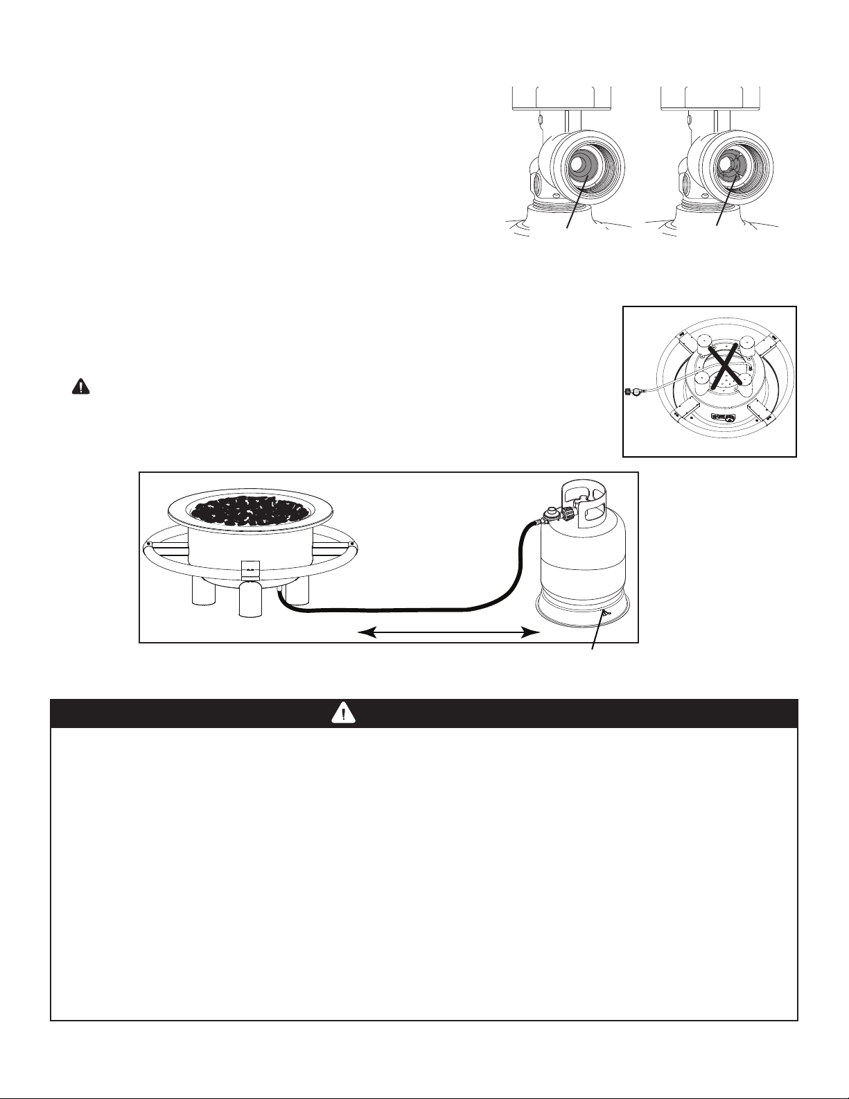
• Do not store a spare propane cylinder on or near this unit.
• Keep propane cylinder at least 72 inches away from unit while in use.
• Keep hose out from any pathways to eliminate any accidental damage and avoid a trip hazard.
• Keep all electrical cords and fuel supply hose away from heated surfaces.
• Never leave this unit unattended while in use.
• It is imperative that the control compartment, burner and circulating air passageways of the appliance
are kept clean.
GENERAL WARNINGS:

3
WARNING
• Do not operate on a boat or vehicle. Always place the re pit on a rm and level noncombustible
surface.
• When in use, minimum clearance to adjacent combustible materials, gasoline and other ammable
liquids and vapors; sides-36 inches (91 cm); top-72 inches. Certain items or materials, when stored
under the re pit or nearby will be subjected to radiant heat and could be seriously damaged.
• Children and adults should be alerted to the hazards of high surface temperatures and should stay
away to avoid burns or clothing ignition.
• Your children and pets should be carefully supervised when they are in the area of the re pit.
• Clothing or other ammable materials should not be hung from re pit or placed on or near the re pit.
• Any guard or other protective device removed for servicing the re pit must be replaced prior to
operation.
• Do not add water into the unit.
• Do not use the re pit if any part has been under water. Immediately call a qualied technician to
inspect the appliance and to replace any part of the control ignition and gas control that has been
under water.
• This unit is not intended for cooking.
• Fire pit is hot when in use. To avoid burns:
• DO NOT attempt to move the re pit while in use.
• Wear protective gloves or oven mitts.
• DO NOT touch any hot re pit surfaces.
• DO NOT wear loose clothing or allow hair to come in contact with re pit.
• Always remove protective cover before operating.
• Do not set protective cover over the unit until it is turned off and completely cooled down.
• If unit is stored indoors, detach the propane cylinder and leave outdoors.
USE CAUTION AND COMMON SENSE WHEN OPERATING YOUR GAS FIRE PIT.
FAILURE TO ADHERE TO THE SAFETY WARNINGS AND GUIDELINES IN THIS MANUAL
COULD RESULT IN SEVERE BODILY INJURY OR PROPERTY DAMAGE.
Minimum Clearance
36 inches (91.4 cm)
Minimum Clearance
36 inches (91.4 cm)
Minimum Clearance
36 inches (91.4 cm)
Minimum Clearance
36 inches (91.4 cm)
WARNING:
Combustible material should not be
within 72 inches (182.9 cm) of the
top of the unit, or within 36 inches
(91.4 cm) of the side of the unit.
WARNING: Failure to position the parts in accordance with this diagram or failure to use only parts
specically approved with this appliance may result in property damage and personal injury.

4
Product Name Dual Fuel Gas Fire Pit
Model No. PIT2141AS
Rated Heat Output 62,000 BTU/h (18.15 kWh)
Fuel Propane-LPG or Natural Gas-NG
Gas Supply 20 lb. LP-gas cylinder
Manifold Pressure 11 inches WC for LP / 7 inches WC for NG
Orice Size (diameter) 2.55 (0~+0.02)mm
Gas Supply Pressure Maximum 250 PSI; Minimum 5 PSI
WARNING
LP GAS CYLINDER (NOT SUPPLIED WITH THIS FIRE PIT)
The LP cylinder is available for purchase at the same location the re pit was purchased.
The LP (Liquid Propane) gas cylinder specically designed to be used with this re pit must
have a 20 lb. (9.1 kg) capacity incorporating a Type 1 cylinder valve and an over-lling protection
device (OPD).
• DO NOT connect this re pit to an existing #510 POL cylinder valve with Left Hand threads. The
Type 1 valve can be identied with the large external threads on the valve outlet.
• DO NOT connect to a propane cylinder exceeding this capacity.
• DO NOT connect to a cylinder that uses any other type of valve connection device.
LP GAS CYLINDER SPECIFICATIONS:
When purchasing or exchanging a cylinder for your gas re pit, it must be constructed and marked in accordance
with the specications for LP gas cylinders of the U.S. Department of Transportation (DOT) or the National
Standard of Canada, CAN/CSA-B339 Cylinders, Spheres and Tubes for Transportation of Dangerous Goods; and
Commission, as applicable; and provided with a listed over-lling prevention device (OPD), and provided with a
cylinder connection device compatible with the connection for outdoor gas replace. The cylinder must be provided
with a shut off valve terminating in a LP gas supply cylinder valve outlet specied, as applicable, for connection No.
791 in the Standard for cylinder connection devices, ANSI 221.81. CSA 6.25.
The cylinder must also be equipped with:
• A shut-off valve terminating in a Type 1 gas cylinder valve outlet.
• A Type 1 valve that prevents gas ow until a positive seal is obtained.
• An arrangement for vapor withdrawal.
• A collar to protect the cylinder shut-off valve.
• A safety relief device having direct communication with the vapor space of the cylinder.
• A listed over-lling prevention device (OPD).
FIRE PIT SPECIFICATIONS:
CYLINDER SPECIFICATIONS AND INSTALLATION:

5
• Allow only qualied licensed LP gas dealers to properly ll or repair your LP gas cylinder.
• New tanks should be purged prior to lling; inform LP gas dealer if you are using a new tank.
• DO NOT allow the cylinder to be lled beyond 80% capacity. Over-lled tanks can create a
dangerous condition. Over-lled tanks can build-up pressure and cause the relief valve to expel
propane gas vapors. The vapor is combustible and if it comes in contact with a spark source or
ame an explosion causing severe burns, bodily harm, or death could occur.
• Always use a protective cylinder cap when re pit is not connected to cylinder.
• If you exchange a cylinder with a qualied exchange program, the new cylinder must have
a Type 1 valve and an over-lling prevention device (OPD).
• Inspect the propane tank valve rubber seal for cracks, wear or deterioration prior to use. A
damaged rubber seal can cause a gas leak, possibly resulting in an explosion, re or severe
bodily harm.
FILLING THE LP GAS CYLINDER:
WARNING
• Turn off the cylinder valve when your re pit is not in use.
• Handle the tank with care.
• Always secure the cylinder in an upright position.
• Never connect an unregulated LP gas cylinder to your re pit.
• DO NOT expose LP gas cylinders to excessive heat or ignition sources.
• DO NOT store a spare LP gas cylinder under or near your re pit.
• Allow only qualied LP gas dealers to ll or repair your LP gas cylinder.
• DO NOT allow the cylinder to be lled beyond 80% capacity.
• Read and follow all warnings and instructions that are on the cylinder and that accompany this
product.
WARNING
• Never store a spare LP gas cylinder under or near your re pit. This could cause excess
pressure to be expelled through the vapor relief valve resulting in re, explosion, or severe
personal injury including death.
Note: PROPANE GAS IS HEAVIER THAN AIR AND WILL COLLECT IN LOW AREAS.
PROPER VENTILATION IS EXTREMELY IMPORTANT.
• Keep the ventilation opening(s) of the LP gas cylinder enclosure free and clear from
obstructions and debris.
• DO NOT insert any foreign objects into the valve outlet. Damage to the back-check could
result. A damaged back-check can cause a leak, possibly resulting in explosion, re, severe
bodily harm, or death.
DANGER

6
INSTALLING THE LP GAS CYLINDER (TANK) ONTO THE FIRE PIT:
1. Check that the cylinder valve is closed by turning the knob clockwise. Inspect
cylinder valve rubber seal for cracks or deterioration. Do not use propane tank
with damaged seal as a gas leak may occur.
2. Place the cylinder at least 72-inches away from re pit to prevent it from
overheating.
WARNING: DO NOT route the hose under the re pit.
3. Locate hose where it will not be a trip hazard and the hose is not kinked or
damaged.
4. Install tank into tank holder and fully tighten the tank retaining screw to secure
the tank.
• Inspect the propane tank valve rubber seal for cracks,
wear or deterioration prior to use. A damaged rubber
seal can cause a gas leak, possibly resulting in an
explosion, re or severe bodily harm.
• Inspection should be done each time the propane tank is
connected to the re pit, has been relled, exchanged or
has not been used for more than 60 days.
• Do not use a propane tank with a damaged rubber seal.
Exchange the tank or have the rubber seal replaced at a
qualied propane lling station.
LP GAS CYLINDER (TANK) RUBBER SEAL INSPECTION:
Good
Rubber Seal
Damaged
Rubber Seal
HOSE / REGULATOR SPECIFICATIONS AND INSTALLATION:
The pressure regulator and hose assembly supplied with your re pit must be used.
• DO NOT attempt to connect re pit, as purchased for LP (propane) gas, to any other fuel supply
source such as a natural gas line. For dual fuel re pits that can be converted to natural gas, a
Even Embers conversion kit must be purchased and installed for use with natural gas.
• DO NOT use any other pressure regulator/hose assembly other than the one supplied with your re
pit. Replacement pressure regulator/hose assembly must be part No 2141-600-2141-0, which can be
obtained by contacting customer service at 1-855-735-9922.
• DO NOT attempt to adjust or repair a regulator. The regulator is designed to operate at a
maximum output pressure of 11 inches of water column (2.74 kPa).
• Ensure the tank valve is CLOSED prior to connecting the LP gas cylinder to your re pit.
Turn the valve knob clockwise to properly close the valve. Read and follow all instructions
and warnings on the supply hose safety tags. Read and follow all warnings in this manual
concerning the safe use of LP gas cylinders and the hose and regulator before connecting
cylinder to re pit. Read and follow all warnings on the LP cylinder.
WARNING
72” Minimum
Retaining Screw

7
HOSE / REGULATOR:
Your re pit is equipped with a Type 1 connection device with the following features:
1. The system will not allow gas ow from the cylinder until a positive connection to the valve has been made.
Note: The cylinder valve and re pit control knob must be turned OFF before any connection is made or
removed.
2. A thermal device that will shut off the gas ow if the device is subject to temperatures above 240°F to 300°F
(115°C to 150°C). If this should happen, remove the entire regulator assembly and dispose of properly. A
replacement regulator assembly can be purchased by contacting customer service at 800-527-0717. The cause
of the excessive heat should be determined and corrected before using your re pit again.
3. A regulator ow limiting device, when activated, restricts the ow of gas to 10 cubic feet per hour. If the ow
limiting device is activated, perform Regulator Resetting Procedure.
CONNECTING HOSE / REGULATOR:
1. Inspect the propane tank valve rubber seal for cracks, wear or
deterioration prior to use. A damaged rubber seal can cause a gas
leak, possibly resulting in an explosion, re or severe bodily harm. Do
not use a propane tank with a damaged rubber seal.
2. Attach or detach regulator to the LP gas cylinder only when cylinder is
at rest in tank holder.
3. Check that the cylinder valve is closed by turning the knob clockwise.
4. Check that the re pit’s burner control knob is in the “OFF” position.
5. Visually inspect the hose assembly prior to each use for evidence of damage, excess wear, or
deterioration. If found, replace the assembly before using your re pit. Only the manufacturer’s supplied
replacement should be used.
6. Remove the protective plastic cap from the cylinder valve.
7. Check that the hose does not contain kinks, does not contact sharp edges, and does not contact surfaces
that may become hot during use.
8. Hold regulator and insert the brass nipple into the LP cylinder valve outlet. Ensure that the device is
centered properly.
9. Turn the large coupling nut clockwise by hand and tighten to a full stop. Take care not to cross thread the
coupling nut onto the cylinder valve. Do not use tools to tighten connection.
Note: If you are unable to make the connection, repeat Steps 7 and 8.
10. Leak check all ttings before lighting your re pit. See section on “Leak Testing” in this manual.
Note: To remove regulator from propane tank, turn off the tank valve and rotate the large coupling nut
counter-clockwise and remove.
REGULATOR RESETTING PROCEDURE:
Mini Reset:
Turn the control knob to “OFF”, turn off the cylinder valve. Wait one minute. Slowly turn cylinder valve ON
and relight re pit. If burner ame is higher and re pit heats up properly – reset is complete.
Full Reset:
Turn the control knob to “OFF”, turn off the cylinder valve. Disconnect hose and regulator from cylinder. Wait
two minutes, reattach hose and regulator and perform leak test.
WARNING
• Never use your re pit without leak testing all gas connections, hoses and propane tank. Follow
the section on “Leak Testing” in this manual for proper procedures.
LEAK TESTING:
Inspect Rubber Seal (see page 6)

To prevent re or explosion hazard:
• DO NOT smoke or permit ignition sources in the area while conducting a leak test.
• Perform test OUTDOORS in a well ventilated area that is protected from the wind.
• Never perform a leak test with a match or open ame.
• Never perform a leak test while the re pit is in use or while re pit is still hot.
DANGER
WHEN TO PERFORM A LEAK TEST:
• After assembling your re pit and before lighting for the rst time, even if purchased fully assembled.
• Every time the LP gas cylinder is relled, exchanged or if any of the gas components are disconnected or
replaced.
• Any time your re pit has been moved.
• At least once per year or if your re pit has not been used for more than 60 days.
CHECKING FOR LEAKS:
CAUTION: Strong odors, colds, sinus congestion, etc. may prevent the detection of propane by smell.
Use caution and common sense when testing for leaks.
Note: The leak test must be performed in an area that has adequate lighting in order to see if bubbles are
developing and not in a windy or noisy area so larger leaks can be detected by smell or sound.
1. Create a mixture of 50% water and 50% liquid dishwashing soap.
2. Ensure the control knob is set to the “OFF” position.
3. Turn on the gas at the cylinder valve. Turn the cylinder valve knob counter-clockwise to full open. If you
hear a rushing sound or smell gas, turn the gas off. Tighten any leaking connections. If leak is detected at
connection nut and tightening does not stop leak, reinspect propane tank rubber seal.
4. Apply the soapy water mixture to the following:
Supply tank (cylinder) weld.
Connection nut to tank valve.
Back side of connection nut to brass nipple.
Brass nipple connection into regulator.
5. Check each place listed (A–H) for growing bubbles, which indicates a leak. Large leaks may not be
detected by bubbles but should produce a rushing sound or gas smell.
6 Turn off gas supply at cylinder valve.
7. Turn on control knob to release gas pressure in hose.
8. Turn control knob to “OFF” position.
9. Tighten any leaking connections. If leak is detected at connection nut and tightening does not stop leak,
reinspect propane tank rubber seal. (see page 6)
10. Repeat soapy water test until no leaks are detected.
11. Turn off gas supply at cylinder valve until you are ready to use your re pit.
12. Wash off soapy residue with cold water and towel dry.
13. Wait 5 minutes to allow all gas to evacuate the area before lighting re pit.
WARNING: DO NOT use the re pit if leaks cannot be stopped. Contact a
qualied gas appliance repair service.
A
B
C
D
Watch For Bubbles
8
A
B
C
D
E
F
G
H
E
F
G
H
Regulator connections to gas supply hoses.
Hose connection to gas manifold.
The full length of gas supply hose.
Tank valve to cylinder.

9
WARNING
WARNING
Property damage, bodily harm, severe burns, and death could result from failure to follow these
safety steps. These steps should be performed after the re pit has been assembled and prior to
each use. DO NOT operate this re pit until you have read and understand ALL of the warnings and
instructions in this manual.
• Ensure that the re pit is properly assembled.
• Inspect the gas supply hose for burns, chaffing, kinks, and proper routing before each use. If it is
evident there is excessive abrasion or wear, or the hose is cut, it must be replaced prior to the re pit
being used. Replace with hose and regulator Model No. 2141-600-2141-0, which can be obtained by
contacting customer service at 1-855-735-9922.
• Leak check all gas connections, hose and propane tank. See section on “Leak Testing”.
• DO NOT obstruct the ow of ventilation air.
PRE-START CHECK LIST:
LIGHTING INSTRUCTIONS:
Read, understand and follow all warnings and instructions contained in this manual. DO NOT skip any
of the warnings and instructions contained in the preceding sections of this manual.
Follow the instructions exactly.
1. Remove the re pit cover before attempting to light a burner so that fumes do not accumulate
inside the re pit.
2. Check that the burner control knob and the cylinder valve are turned to the “OFF” position.
3. Turn on the fuel supply by slowly rotating the cylinder valve knob counter-clockwise to full open.
4. DO NOT stand with head, body, or arms over the re pit when lighting.
LOCATION:
• Your re pit must be installed on a noncombustible at, stable surface, away from any combustible
material or construction.
• The re pit shall be used only outdoors in a well-ventilated space and shall not be used in a building,
garage or any other enclosed area.

10
LIGHTING THE FIRE PIT:
1. Make sure control knob is in OFF position.
2. Push and turn control knob to “LOW”.
3. Push in and hold control knob while pressing ignitor for 3 to 5 seconds.
If ignition does not occur in 5 seconds, turn knob to “OFF,” wait 5
minutes and repeat lighting procedure.
4. Continue to push in control knob for 15 seconds after burner is lit. Then
release the control knob and adjust to desired heat output.
Note: Turn off LP supply at cylinder when re pit is not in use.
MATCH LIGHTING THE FIRE PIT:
1. Make sure control knob is in OFF position.
2. Strike a long wooden match and place approximately 1/2”
(1 to 2 cm) from the burner.
3. Push and turn control knob to “LOW” and continue to push in control
knob.
4. Continue to push in control knob for 15 seconds after burner is lit. Then
release the control knob and adjust to desired heat output.
5. If the burner does not light, turn the control knob to “OFF” and
wait 5 minutes for gas to dissipate and repeat lighting procedure.
6. If the burner does not light within the rst few attempts of match
lighting, there is a problem with the gas supply. Turn off the gas at the
burner and cylinder. DO NOT attempt to operate the re pit until the
problem is found and corrected. See “Trouble Shooting” section of this
manual.
TURNING OFF THE FIRE PIT:
1. Turn off the cylinder valve.
2. Turn burner control knob to the “OFF” position.
Note: Turn off LP cylinder rst to prevent gas from being left in the system under pressure.
CAUTION!
• The cylinder valve should always be in the off,
or closed, position when the re pit is not in use.
Control Knob
OFF
HIGH
LOW
To turn off the cylinder valve,
turn knob clockwise until it stops.
Ignitor

• Keep the appliance free and clear of combustible materials, gasoline
and other ammable vapors and liquids.
• For safe and peak performance of your re pit, perform these checks
at least twice per year or after extended periods of storage.
• Be sure to tighten up all hardware (nuts, screws, etc.) at least twice
per year.
CAUTION: Some parts may contain sharp edges. Wear protective gloves
if necessary.
• Although your burner is constructed of stainless steel, it
may corrode as a result of the extreme heat. Regularly
inspect the burner for cracks, abnormal holes, and other
signs of corrosion damage. If found, replace the burner.
• DO NOT block ventilation areas in sides or bottom
compartment of re pit. The burner tube can become
blocked by spiders and other insects building their nests.
Blocked burner tubes can prevent gas ow to the burner and
could result in a burner tube re or re beneath the re pit.
To clean the burner assembly follow these instructions to
clean and/or replace parts of burner assembly or if you have
trouble igniting the re pit.
1. Turn gas off at control knob and LP cylinder tank valve.
2. Remove lava rocks.
3. Remove three screws on burner feet.
4. Carefully lift burner up and away from valve nozzle.
5. Use a narrow bottle brush or a stiff wire bent into a small
hook to run through burner opening or use compressed air
to blow into burner opening and out the ame ports. Check
each port to make sure air comes out each hole.
CAUTION: Wear eye protection when using compressed air.
6. Use a wire brush to clean the entire outer surface of burner
to remove residue and dirt.
7. Check burner for damage, if any cracks or holes are
found replace burner.
8. Replace burner in re pit, orient burner CORRECTLY.
IMPORTANT: Burner opening must slide over valve nozzle.
9. Replace screws on burner feet.
Note: Follow the “Gas Leak Testing” section of this
manual. Relight burner to verify proper operation.
Debris
Screws
Valve Nozzle
Burner Opening
11
BURNER CLEANING AND MAINTENANCE:
Normal ame height is 12” to 15”

12
To obtain the best performance from your re pit, you must perform the following storage and maintenance
activities on a regular basis:
• Allow at least 35 minutes for the re pit to cool down after use, then disconnect and remove the cylinder.
• Cylinder must be stored outdoors in a well-ventilated area out of the reach of children. Disconnected
cylinders must have protective plastic cap installed and must not be stored in a building, garage or
any other close area.
• Storage indoor is permissible only if the cylinder is disconnected and removed.
• Keep the re pit area clear and free from combustible materials, gasoline and other ammable vapors and
liquids.
• If the re pit is not in use, it must be covered to protect from weather or other adverse elements.
• Installation and repair should be done by a qualied service person. The re pit must be inspected at least
annually by a qualied service person.
• It is imperative that the control compartment, burners and circulating air passageways of the re pit be kept
clean.
STORAGE AND MAINTENANCE:
TROUBLE SHOOTING:
Problem Possible Cause Prevention/Cure
Gas Odor Gas Leak Leak check all connections
Burner won’t light while
using a match
Low gas pressure Check gas supply pressure
Regulator isn’t connected securely Tighten regulator connection to propane tank
Clogged or dirty burner ports Clean burner ports-see manual section
Gas ow is obstructed Check hose for kinks and bends
Incorrect burner ame Burner ports are clogged or blocked Clean burner ports
Clogged or dirty burner ports Clean burner ports-see manual section
Fire Pit won’t light Ignitor pin and burner are wet Dry off with soft cloth
Ignitor pin is broken Contact Even Embers for a replacement part
Electrode wire is loose or disconnected Reconnect wire to the ignitor
Electrode wire is shorting Contact Even Embers for a replacement part
Fire Pit emits a lot of
black smoke
Flame is obstructed at burner Check burner ports are free of any debris
Regulator hose is kinked Straighten hose of all bends and kinks
Sudden drop in gas ow No gas ow Check that the propane cylinder is not empty
Regulator ow limiting device has been activated Follow “Resetting Regulator Procedure” section in this manual
Flame blows out easily High or gusting winds Increase ame to “HIGH”
No gas ow Check that the propane cylinder is not empty
Regulator ow limiting device has been activated Follow “Resetting Regulator Procedure” section in this manual

13
ASSEMBLY INSTRUCTIONS:
READ ALL SAFETY WARNINGS & ASSEMBLY INSTRUCTIONS CAREFULLY
BEFORE ASSEMBLING OR OPERATING YOUR FIRE PIT.
WE RECOMMEND TWO PEOPLE WORK TOGETHER WHEN ASSEMBLING THIS UNIT.
The following tools are required to assemble this Red Stone Gas Fire pit:
• Phillips Screwdriver
Note: Most hardware is pre-attached to the re pit. You may need to loosen some screws
partially while others may need to be removed in order to assemble parts. The screws that
you remove will be re-used so don’t misplace this hardware.
Extra screws are included in a small bag with the owners manual.
PARTS LIST:
1 Bag of Lava Rocks
4 Rail Supports
4 Rail Braces
4 Rails
1 Fire Pit Body
4 Feet
1 Tank Holder
1 Allen Wrench
1 AAA Battery (Pre-Installed)
1
2
3
4
5
1
2
3
4
5
6
6
78
7
8
9

14
1
Attach rail supports to re
pit body using eight M6 x 12
mm bolts.
2
Set rails in place. Use Allen
wrench to attach rails to rail
supports using eight M6 x
60 mm bolts and M6 nuts.
Secure rail braces to rail
supports using sixteen M4 x
10 mm bolts.

15
3
Attach feet to re pit body
using eight M6 x 12 mm
bolts.
4
Spread lava rocks evenly
around re pit base. Do not
pile lava rock over burner
tube more than 1/2 inch.

16
Red Stone PIT2141AS Assembled

OM2141AS
0422, 0522
Owner’s Manual for Model
PIT2141AS
©2022 The Boltz Group LLC.
Carrollton, Texas 75006 U.S.A.
www.evenembers.com
The Boltz Group warrants to the original purchaser that the Red Stone Gas Fire Pit is free from defects due to workmanship or materials for:
One-year: on valves, frame, housing, and other related parts
The Boltz Group’s obligations under this warranty are limited to the following guidelines:
• This warranty does not cover re pits that have been altered/modied or damaged due to: normal wear, rust, abuse, improper maintenance
and/or improper use.
• This warranty does not cover surface scratches, rust or heat damage to the nish, which is considered normal wear.
• The Boltz Group may elect to repair or replace damaged units covered by the terms of this warranty.
• This warranty extends to the original purchaser only and is not transferable or assignable to subsequent purchasers.
The Boltz Group requires reasonable proof of purchase. Therefore, we strongly recommend that you retain your sales receipt or invoice. To obtain
replacement parts for your Red Stone Gas Fire pit under the terms of this warranty, please call Customer Service Department at 1-855-735-9922.
A receipt will be required. The Boltz Group will not be responsible for any re pits forwarded to us without prior authorization.
EXCEPT AS ABOVE STATED, THE BOLTZ GROUP MAKES NO OTHER EXPRESS WARRANTY.
THE IMPLIED WARRANTIES OF MERCHANTABILITY AND FITNESS FOR A PARTICULAR PURPOSE ARE LIMITED IN DURATION TO THOSE
LISTED ABOVE FROM THE DATE OF PURCHASE. SOME STATES DO NOT ALLOW LIMITATIONS ON HOW LONG AN IMPLIED WARRANTY
LASTS, SO THE ABOVE LIMITATION MAY NOT APPLY TO YOU.
ANY LIABILITY FOR INDIRECT, INCIDENTAL OR CONSEQUENTIAL DAMAGES ARISING FROM THE FAILURE OF THE RED STONE GAS
FIRE PIT TO COMPLY WITH THIS WARRANTY OR ANY IMPLIED WARRANTY IS EXCLUDED. CUSTOMER ACKNOWLEDGES THAT THE
PURCHASE PRICE CHARGED IS BASED UPON THE LIMITATIONS CONTAINED IN THE WARRANTY SET OUT ABOVE. SOME STATES
DO NOT ALLOW THE EXCLUSION OR LIMITATION OF INCIDENTAL OR CONSEQUENTIAL DAMAGES, SO THE ABOVE LIMITATION OR
EXCLUSION MAY NOT APPLY TO YOU. THIS WARRANTY GIVES YOU SPECIFIC LEGAL RIGHTS, AND YOU MAY ALSO HAVE OTHER
RIGHTS WHICH VARY FROM STATE TO STATE.
WARRANTY
Table of contents
Popular Outdoor Fireplace manuals by other brands

Empire
Empire OLL60FP12SN-1 Installation instructions and owner's manual

ELEMENTI
ELEMENTI Birmingham Dinning Table OFG202LP owner's manual

Outdoor GreatRoom Company
Outdoor GreatRoom Company UPT-1242 installation instructions

CobraCo
CobraCo FB-6200 owner's manual

AMD DIrect
AMD DIrect Pro Series Installation and operating instructions

ELEMENTI
ELEMENTI Brooklyn owner's manual

IKEA
IKEA BOHOLMEN manual

Prism Hardscapes
Prism Hardscapes Moderno Series Installation, operation & maintenance manual

Windward Design Group
Windward Design Group MGP manual

Bond
Bond 52168 manual

SNAN
SNAN RY43-0001 user manual

Warming Trends
Warming Trends CROSSFIRE CFB60 NG Owner's Guide and Instruction Manual