WARNINGS AND SAFETY INFORMATION
SAVE THESE INSTRUCTIONS — This manual contains important safety
instructions. Do not operate the system unless you have read and understood
this manual. REDARC recommends that the Inverter Wiring Kit referenced in this
manual be installed by a suitably qualified person.
Disclaimer: REDARC accepts no liability for any injury, loss or property damage
which may occur from the improper or unsafe installation or use of its products.
SAFETY MESSAGE CONVENTIONS
Safety messages in this manual contain a signal word that indicates the level of the
hazard, as follows:
WARNING Indicates a potentially hazardous situation which could result
in death or serious injury to the operator or to bystanders.
CAUTION Indicates a potentially hazardous situation which may result in
moderate or minor injury to the operator or to bystanders.
NOTICE Indicates a situation that may cause equipment damage.
WARNING
Risk of electrical shock. Do not disassemble the inverter - the internal circuitry
contains hazardous voltages. Attempting to service the unit yourself may result
in electric shock or fire and could void the unit warranty.
Risk of electrical shock. Do not expose the inverter to rain, snow, spray, liquid
or dust. Doing so may result in damage to the inverter or other appliances
installed in the system or result in electric shock or fire.
Risk of electrical shock. Operation of the inverter without a proper ground
connection may result in an electrical safety hazard. Ensure proper ground
connection is made during installation. For fixed and/or transportable (vehicle)
installations, install according to appropriate AS/NZS standard.
Risk of electrical shock. Before proceeding, carefully check that the inverter is
not connected to any batteries and that all cables are disconnected from any
electrical sources.
Do not connect the output terminals of the inverter to an incoming AC source.
CAUTION
This appliance is not intended for use by persons (including children) with
reduced physical, sensory or mental capabilities, or lack of experience and
knowledge, unless they are supervised or have been instructed on how to
use the appliance by a person responsible for their safety. Children should be
supervised to ensure that they do not play with the appliance.
Do not operate the inverter with damaged or substandard cabling. Selecting
the wrong cable or fuse size could result in harm to the installer or user and/or
damage to the inverter or other appliances installed in the system. The installer
is responsible for ensuring that the correct cable and fuse sizes are used when
installing this inverter.
Ensure recommended torque values are observed and the DC Input
connections to the Inverter are tight (torque to 11.7–13 Nm (9–10 ft-lbs)). Any
loose connections could result in overheating and can be a potential hazard.
Some components in the inverter can cause arcs and sparks. Do not put
batteries, flammable materials, liquids, or anything that should be ignition–
protected around the inverter. Doing so may result in fire or explosion.
Be extra cautious to reduce the risk of dropping a metal tool onto a vehicle
battery. Doing so might cause the battery to spark or might short-circuit the
battery or other electrical parts that may cause an explosion.
Remove personal metal items such as rings, bracelets, necklaces, and watches
when working with a battery. A battery can produce a short-circuit current high
enough to weld a ring or the like to metal, causing a severe burn.
If battery acid contacts your skin or clothing, remove the affected clothing and
wash the affected area of your skin immediately with soap and water. If battery
acid enters your eye, immediately flood the eye with running cold water for at
least 10 minutes and seek medical assistance immediately.
NEVER smoke or allow a spark or flame in vicinity of battery. This may cause
the battery to explode.
Batteries are capable of providing very large currents in the case of a short
circuit. A fuse must be installed on the positive supply cable as close as
practical to the battery. Failure to do so provides inadequate protection against
fire in the case of a short circuit.
NOTICE
Install the inverter in a well-ventilated area with reasonable clearance. Do not
install the inverter in a zero clearance compartment or obstruct the ventilation
openings. Doing so may result in the inverter overheating and ultimately
damage the inverter.
Reverse Polarity connection will blow the internal fuse and may damage the
inverter permanently and could void the warranty.
Do not operate appliances that may feed power back into the inverter. Damage
to the inverter may occur as a result.
The RS3 Inverters are fitted with RCBO, which incorporates both a residual
current device as well as a circuit breaker. The RS3 Inverters comply with AS/
NZS 4763 standard and can be used to power fixed wiring in accordance with
AS/NZS 3001 when installed by a licensed electrician. A proper ground bond is
required for the RCD to work as intended.
Ensure that the frequency output of the inverter matches the frequency
requirements of all loads attached to the inverter. Attempting to use appliances
that requires an AC frequency different to the inverter output may result in
damage to your appliances.
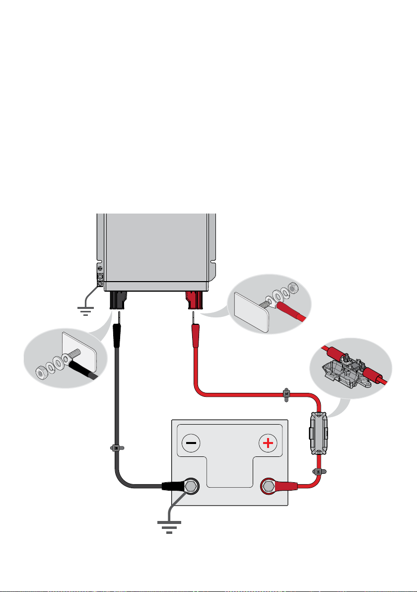
SAFETY BEFORE DC INPUT CABLE CONNECTIONS
CHASSIS GROUND CONNECTION
The chassis ground connection must be made to the
ground of the vehicle before making any other connections
to the inverter.
NOTE: The chassis ground cable is not supplied with
the RS3 Inverter Wiring Kit. Refer to the RS3 Inverter
Instruction Manual for further information.
MAIN SWITCH AND AC OUTPUT REQUIREMENTS
Before making the DC Input cable connections, the Main
Switch must be set to the “OFF” position and all loads
must be disconnected from the inverter’s AC output.