REDROTOR RC RROSD PRO V2 User manual

2
Return Policy–Without soldering anything to the board, please apply power to the
board using alligator clips and make sure the Green LED is on. Contact us immediately
if green LED doesn't turn on! Return and Warranty claims are only considered on units
that have not been soldered and within 30 days of purchase date.
Connecting any external voltages to the RROSD 5V rail will destroy the board and
effectively void warranty
Disclaimer!! - Please understand that quadcopters are potentially dangerous machine.
Use the highest level of precaution when working with hot solder iron, Lipo battery and
motors. Make sure to remove props from motor throughout the entire building process.
Solder equipment –Be sure to use a high quality soldering iron with a large tip
especially when soldering the battery and ESC connections.
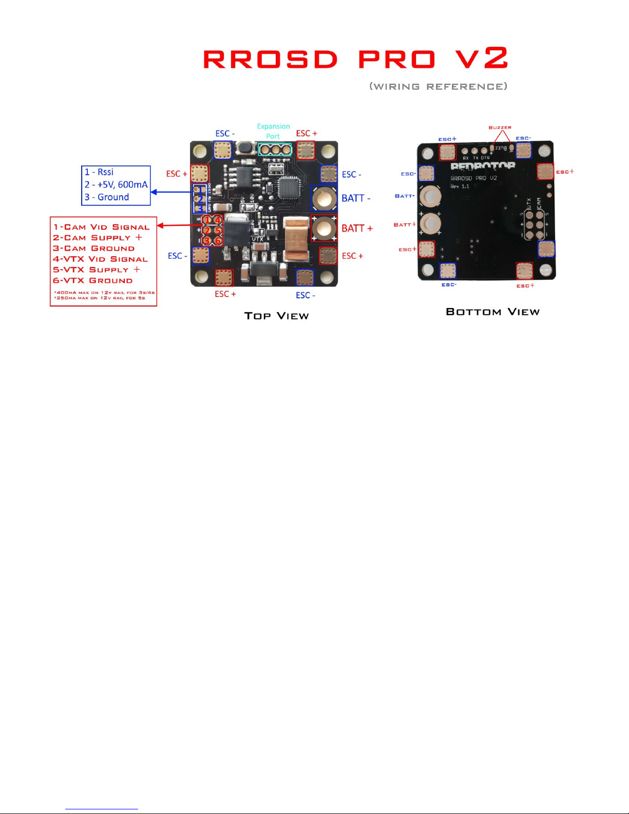
Power output on CAM 5V/12V connector –Because a linear regulators are used, limit
the current draw to less than 400mA on 12V and 600mA on 5V rail to prevent
overheating
6S battery –Please make sure VTX solder-bridge is set to RAW to prevent the 12V
regulator from going into thermal shutdown. A low ESR 470uF capacitor might be
needed
Solder Bridge setting –Please make sure the middle pad is only making connection to
either left or right pad. Soldering all 3 pads together will effectively destroy your RROSD
Pro!
Battery Polarity –Be sure to hook up your battery leads to the proper pads. Positive
lead is clearly marked with ++++ and Negative lead with ----. Reversing this can
potentially damage your board
HEAT!! –This PDB is designed to operate warm to hot. While the heat is not bad
when there’s effective cooling while in flight, do not leave the unit plugged in on the
bench for too long to avoid over heating

3
What is RROSD-PRO V2 PDB?
RROSD PRO V2 is an easy to use power distribution board and OSD designed to maximize FPV
experience while minimizing mini quad build time and reducing the wire clutter mess!
Built-in features
Thick copper and wide power routing to handle the most demanding power setup
Dimension 36mm x 36mm (30.5mm x 30.5mm mounting holes)
Built-in power distribution regulators to handle 3S-6S *note1
Built in multi stages power filter for Video Transmitter and Camera with pre-installed
and conveniently located connectors
12V and 5V output: can be used for FPV cam and accessories
NTSC and PAL can be easily selected using the onboard button
Plug and Play (PnP) OSD information: Flight pack voltage, current draw, total current
consumption, RSSI, flight timer, power statistic summary
Maximum motor current reading 150A total
Automatic flight timer shows actual flight time
The additional lost model buzzer sounds off 5 minutes after the quad has crashed.
RSSI detection (FRsky ppm and analog compatible) displays in percentage
Auto Battery alarm blinks the battery voltage when pack voltage hits the low limit
Low RSSI turns on Buzzer (very handy to locate a downed quad)
Onscreen menu allows user to calibrate pack voltage reading, current calibration, rssi
input, battery alarm level, screen location offset…etc....
Lost model Siren (optional Buzzer)

4
BATT + => Flight battery positive input
BATT - => Flight battery negative input
ESC + => ESCs positive input (top and bottom)
ESC- => ESCs negative input (top and bottom)
LED => Indicator led
Select Button => Function selection button
Top Connector Pin Description:
1. RSSI Input –Use a female-female servo cable to connect to the receiver RSSI signal, pwm
and analog compatible. There’s a built in signal conditioning circuit to convert pwm rssi
to analog voltage. Example: ch-2 on Frsky D4R receiver
2. +5V regulated (flight controller), 600mA max *Do not connect any external voltages
higher than 5V to this pin, doing so will destroy the board
3. Ground
Bottom Connector Pin Description:
1. Cam/VTX Video Signal
2. Cam/Vtx Regulated +12V supply *note1
3. Ground
4. Cam/Vtx Video Signal
5. Cam/Vtx Regulated +12V supply *note1
6. Ground
*note1 - Maximum current draw on 12V rail: 400mA @3s/4s, 250mA @5s, 150mA @6s

5
Solder Bridge Setting:
1. VTX –Connect Middle pad and ‘RAW’ or ‘12V’ pad to set VTX voltage to Battery
input and regulated 12V respectively. *Do not short all 3 pads together or very bad
things will happen
2. CAM –Connect middle pad to ‘5V’ or ‘12V” pad to set CAM voltage. *Do not short all
3 pads together or very bad things will happen
Bottom Buzzer Description:
A. Solder a 5V Buzzer + to positive pad
B. Solder 5V Buzzer - to negative pad
Hold down the Button for 10 seconds upon powering up the RROSD Pro. The LED will turn off to
indicate that the Video mode has been successfully changed
Hold down on the button on The RROSD V2 for 3 seconds to enter into the menu of the RROSD.
To navigate through the menu single click the button to move down an option. Long press to
select an option
RSSI Calibration: To calibrate your RSSI reading, select the high reading with your radio and
receiver powered on and nearby. Flip off the radio and select the low reading to calibrate the
bottom signal range. *The reading you will see on the OSD is the true received strength of the
signal (more accurate and different from a 2 way telemetry signal being sent from a receiver)
Voltage Calibration: This menu item lets you calibrate your voltage reading by entering your own
offset.
Current Calibration: This menu item lets you calibrate your Current reading offset from -20% to
+20%
Set mAH Alarm: Allows you to set mAh consumption alarm. This will cause the respective
indicator to blink on screen when the desired value is reached. We recommend setting mAH to
80% of the battery capacity
Screen Calibration: This menu item allows the OSD lines to move from bottom to top
Exit: Exit the Menu

6
The onboard LED can provide useful information to help trouble shoot the RR
LED Behavior:
Stays full on: this means the RROSD is running but not getting valid video signal from
the camera. Check camera cable
Blinks steadily: this is an indication that the RROSD is running properly and getting valid
video input. Check VTX cabling and make sure channels are set correctly. Check VTX antenna
to make sure there’s no short
LED not on when powered up: RROSD isn’t running. Check battery input cable and
make sure battery is charged
Wrong Video Mode: The garbled image below is an indication of RROSD video is different than
FPV camera’s. You will need to change video mode on one device to make sure they’re both
on NTSC or PAL
Table of contents