M013 Issue: 1.5 Created by: Technical Dept. 8 November 2022
8.0 Priority Tones
The Priority of Trigger inputs is (High Priority) T3 > T2 > T1 (Low Priority). This is important if you wish a tone to override
the current tone
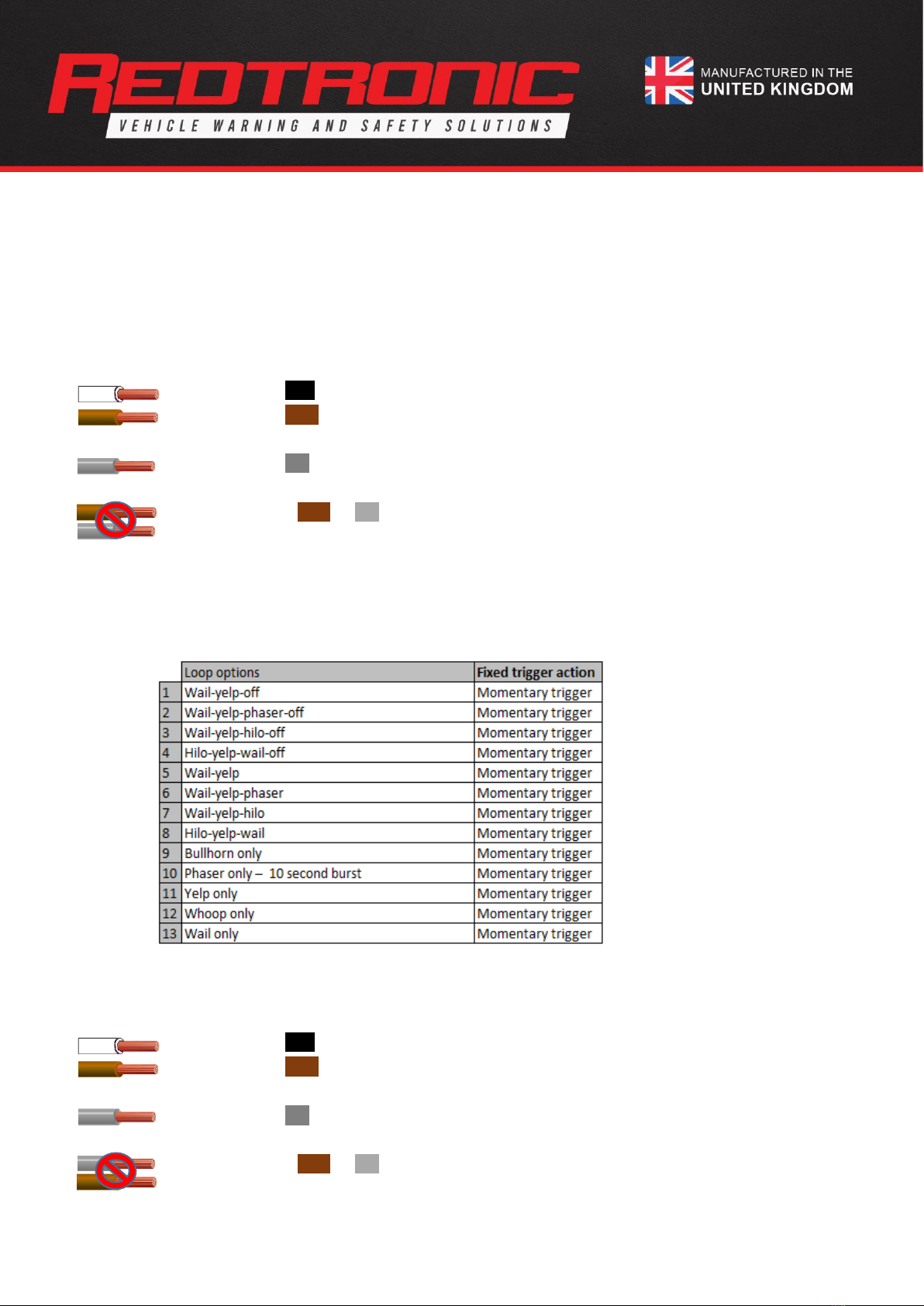
9.0 Night Mode
9.1 Activating Night Mode
There is a ‘Night mode’ available on the device which will reduce the sound output to between 90-100dB when the siren is
activated with ‘night mode’ applied.
a) Ensure the Siren is in ‘Standby’ mode (or siren may be activated)
b) Apply the grey
(Configure)
wire to +ve permanently
c) The sound output will reduce to 90-100dB
Note: the Night Mode sound output level of 90-100dB is a set level due to regulatory requirements and safety. The
level of the Night mode is not able to be altered by the user.
10.0 Test Mode
To enter a ‘test mode’ to ensure the S20 siren is functioning on the correct tone you can follow the following procedure:
a) Ensure the Siren is in ‘Standby’ mode
b) Apply the white
(monitor)
wire to +ve permanently.
c) Apply the brown
(T1 tone trigger) (or T2/T3)
wire to +ve momentarily
d) The tone will start at a level of only 1/25th power of full volume
10.1 Deactivate test mode:
a) Remove the white
(monitor)
wire from +ve supply.
11.0 Monitor Output
11.1 Monitor output function
The monitor output activates when the Siren is outputting a sound of more than 4 watts. Detected faults, such as loss of
communication to the siren driver board, will prevent the signal from activating. Any detected fault will cause the LED
internal to the speaker housing to flash (see 12.0 Diagnostic LED) and the monitor output will deactivate.
The monitor output wire (white) can be connected to an external LED signal, buzzer or computer to monitor speaker
output compliance. This is a positive output that will drive up to 50mA at nominal voltage supply. Please do not put a
heavy load to this wire connection. When there is non-compliance to the standard, the signal will deactivate.