Refine WatchDog 900C User manual

P:910-515-3033
E-mail:sales@refine-tec.com
Add:Surf City,North Carolina USA
WatchDog 900C
Installation and Operations Manual

Table of Contents
Warranty Registration
Safety Notes
Identification
Electrical Supply
Principle of Operation
Installation
Key Functions
Indicator Lights
Remote Control
Operating Instructions
Warranty Information
Spare Parts
Troubleshooting
Ducted Applications
Dehumidifier Storage
Maintenance
Diagram
2
2
3
3
3
3
4
5
6
6
7
8
9
9
11
12
13
1

Warranty Registration
Be sure to note your dehumidifier serial number as you will need it for registration.
Safety Notes
2
Congratulations on purchasing a new Watchdog Dehumidifier. Your new dehumidifier
comes with an extensive warranty plan. To register, simply fill out and return the warranty
form provided in your dehumidifier box.

Identification
For future reference, write down the model, serial number, and date of purchase for your dehumidifier.This is
extremely helpful if you need to seek assistance in the future. The data label on the side of your unit has the key
characteristics of your specific unit.
For additional questions concerning your dehumidifier, the following options are available:
Contact your installing contractor
Call @910-515-3033
Electrical Supply
To reduce risk of injury:
1. Disconnect electrical power before servicing
2. Only plug unit into grounded electrical circuit
3. Do not use an extension cord
4. Do not use a plug adapter
Principle of Operation
The Watchdog Series Dehumidifiers utilizes its integral humidistat to monitor the conditioned space.When the
relative humidity goes above the selected set point, the dehumidifier will energize. Air is drawn across an
evaporator coil, which is cooler than the dew point of air. This means moisture will condense out of the air. The
air is then reheated through the condenser coil and distributed back into the
room.
Installation
WARNING:120 Volts AC may cause serious injury from electric shock.
3
Model Number: Watchdog 900C
Date of PurchaseSerial Number:
Power Supply: 115V, 60 Hz(220V,50Hz) AC Only 1 Phase
Outlet Requirement: 3-Prong, GFI
Circuit Protector: 15 Amp Time Delay Fuse or Circuit Breaker

• For extended storage or movement of the machine, press the “Drain” button to remove water from
the integral pump’s reservoir.
5. Manual Drain Button
• This mode is not applicable on the WatchDog 900c.
4. Central Control
• When set to continuous, the dehumidifier will run constantly, regardless of the humidity level until
you turn the unit off or switch back to normal humidistat operation. If you would like to switch back
to normal humidistat operation, simply move the setpoint above 36%.
• To switch into continuous mode, simply use the arrow keys to set the humidity below 36%.
At this point the Co nt. light should illuminate green on the display board to indicate you have
successfully switched to continuous mode. The display screen will show “CO”.
3. Continuous Mode
4
The setpoint can be any number between 36-90%. Creating a setpoint means that when the
indoor humidity is lower than the set point machine will stop automatically. Conversely, when
the indoor humidity is higher than the set level, the unit will operate. NOTE: The humidity levels
displayed are approximate only (+/- 5%).
• Use the up and down arrow buttons to set the desired humidity setpoint on the display screen.
2. Arrow Buttons
88
• Use this Button to turn the dehumidifier on and off.Press once to turn the machine on. You will hear one beep
and the light will illuminate red. Press the power button a second time and you will hear one beep as the
machine shuts down. Note that there is a one minute fan delay on shutdown.
1. Power Key
power
Key Functions
If the unit is handled in such a manner that the compressor did not remain in the upright position,
you will need to place it on a level surface, then wait a minimum of 2 hours before turning “on”.
Step #2: Set Up Drain Line
The included drain line attaches to unit via a compression tupe fitting on the discharge end of the unit.
To attach drain line, remove the compression nut and slide it over the end of the hose to be attached to
unit.Slide compression nut side of hose over the insert on the compression fitting completely. Tighten
compression nut.
Step #3: Plug unit into 15 amp grounded circuit.

6. Pump Trouble Warning
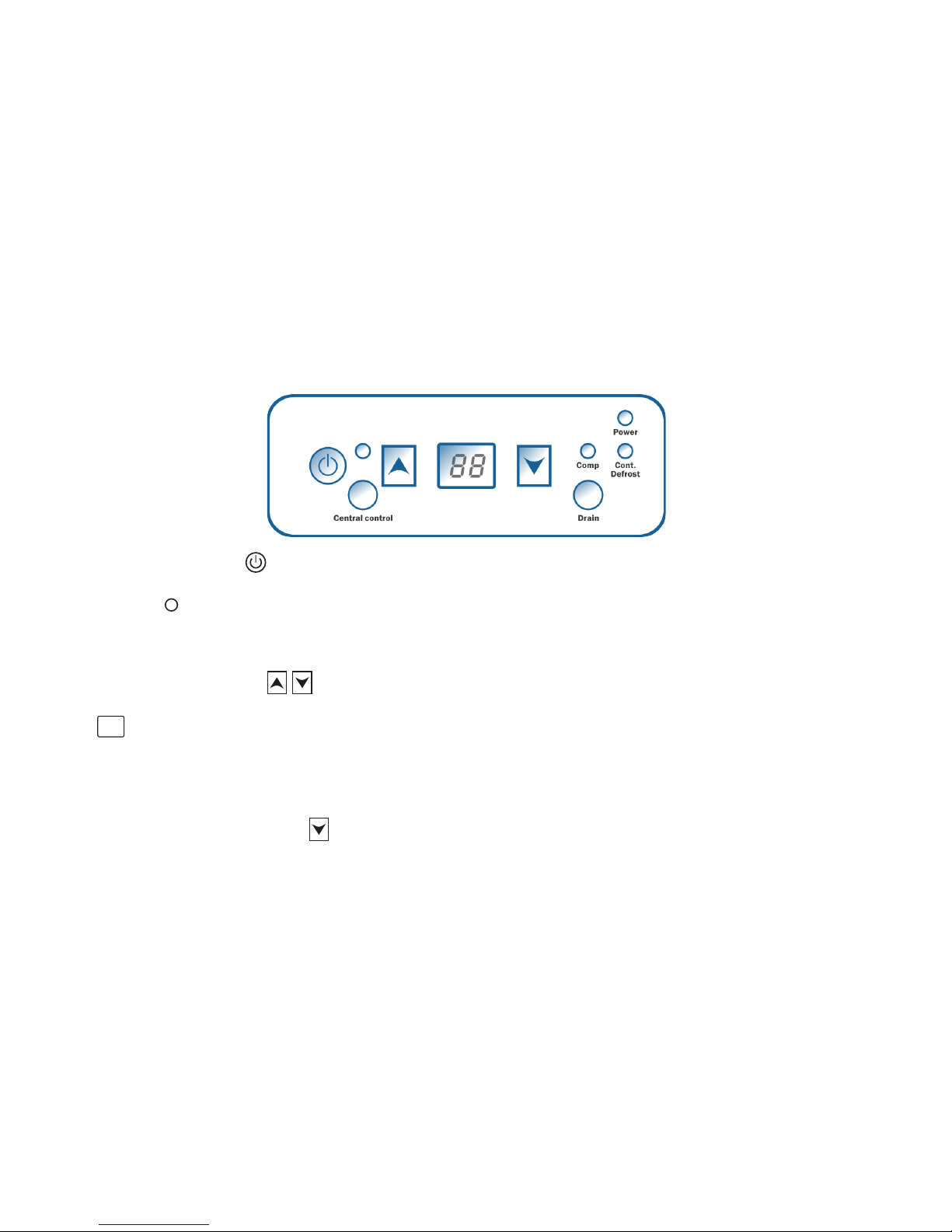
Indicator Lights
1.Humidity Display Screen
1. When the unit is powered on, it shows the indoor humidity.
2. While setting the desired humidity level, the screen will show the set humidity. After a brief delay,
the display will revert to indoor humidity level.
2. Power Indicator Light
This light indicates that the unit is properly powered on and ready to perate. Always make sure the unit is “off”
prior to performing any service.
3. Continuous Mode/AutoDefrost Light
4. Compressor Light
When the compressor light glows red, it indicates the compressor has been initiated but is currently warming up.
Once the compressor light switches to green, it indicates the compressor is in working status.
5. Unit Indicator Light
When the unit indicator light is red, it illustrates the dehumidifier is in unit mode.
While in unit mode, the dehumidifier will use it’s built-in humidity sensor. If using a remote control, unit mode will
allow you to remotely monitor the room conditions where the dehumidifier is located.
6. Remote Indicator Light
When the pump reservoir water level is too high, the high water sensor will activate to prevent over-flow. When
this occurs, the dehumidifier will stop the compressor automatically and the display willshow “E4”. After a 1
minute delay, the fan motor will turn off and the machine will not operate until the problem is resolved. To reset
the unit after an “E4” error, check the pump to verify it is functioning,
then unplug the unit for two minutes.
The display screen has two functions:
When this light illuminates green, it indicates that the dehumidifier is set to continuous operation mode.
When the light glows red, it means the unit is in auto defrost mode and clearing the evaporator coil of any ice buildup.
When the remote indicator light is red, it illustrates the unit is remote mode.
While in remote mode, the dehumidifier will use the sensor on the remote control unit. In this mode,the inlet and
outlet of the dehumidifier can be ducted.
88
power
Cont.
Defrest
Comp
Unit
5

Remote Control Instructions
Watchdog Dehumidifiers can be controlled using an optional remote accessory.The Watchdog Remote
Control connects to your Watchdog Series Dehumidifier via a 25’ CAT 5 cable. The remote control contains an
integrated sensor which gives you multiple options for remotely controlling your unit, in addition to monitoring
the conditions surrounding the dehumidifier.
One application for the remote control is to install the dehumidifier in one room with the conditioned air
ducted into a second room that contains the remote. For example, the dehumidifier could be installed in a
laundryroom and ducted into a living room. The remote would then be mounted in the living room so the remote
sensor can control the humidity and provide easy controls for the user.
Another useful application for the remote control is if the dehumidifier is in area that’s difficult toaccess on
a regular basis. For instance, if your dehumidifier is installed in your crawl space, the remote could be mounted
in your living space or garage. This provides you with an easy way to monitor the dehumidifier.
Operating Instructions
1. Start the machine
Press the power key to turn the machine on.
2. Adjust Settings
Use the up and down arrow keys to adjust your desired setpoint (typically 50-55%).
T
M
P
C
Mode
Temperature
MT c P
Up Button Down Button
LCD Monitor
On/Off
Drain Pump
Continuous
1. On/Off (Power)Button
Press the on/off button and the machine will start running (two beeps). Press the button again to
turn the machine off.
2.Up Button / Down Button
Use the Up and Down arrow buttons to adjust the humidity level.
3. Mode
Use the Mode button to switch between
dehumidification and a ducted application.
The symbol on the display board in
dicates the sensor on the remote control
is being utilized.
The symbol on the display board in
dicates the sensor on the dehumidifier is
being utilized.
4. Temperature
Press the temperature button to display the
current temperature on the screen.
Press the button again to turn off the display.
5. Continuous
Press this button to switch the unit into continuous mode. will appear on the display to indicate
continuous mode.
6.Drain Pump
Use this button if the unit will not be in use for an extended period of time. Pressing the drain pump
button will remove water from the pump reservoir, so the unit can be safely moved or stored.
6

3. Stop the machine
Press the power key again and the machine will stop. Note the fan will continue to operate for 1 minute after
the unit has shut off. NOTE: Do not disconnect power cord to forcemachine to stop. Always use power button.
4. Water Drainage
The Watchdog 900C has both automatic and manual draining. During normal operation, the Watchdog 900C
will automatically drain as required. If you would like to store or move the machine, you may press the drain
button to drain the water from the pump reservoir. The drain will operate for 15 seconds each time the button
is pushed. It may be necessary to push the drain button more than once to completely empty the reservoir.
Watchdog900C Diagram
Front View

WARNING:
Always unplug the unit before doing any maintenance.
Condensate Pump
Your Watchdog 900C is equipped with an integral condensate pump designed to pump water from your
dehumidifier out to the desired drain. This pump requires routine maintenance that is not covered by your
1 year parts warranty. Only a defective pump will be repaired or replaced during the warranty period.
As with all pumps, preventative maintenance is necessary to prevent issues from dirt and slime that may
accumulate in the drain system. This includes the drain pan, hose to the condensate pump, pump reservoir,
pump head float assembly, and discharge tubing.
Preventative Maintenance
At least once per year, clean your pump system
1.
1.
2.
3.
4.
Maintenance
8
Cleaning the machine body
Use a soft damp cloth to clean exterior of unit. Do not use any soap or solvents.
1. Unplug the unit.
2. Slide out the filter.
3. Clean the filter mesh by vacuuming or
washing with warm water (no soap or solvents).
Coil Maintenance
Electrical maintenance
Pump maintenance
Once per year, clean the coils with an approved coil cleaner. The coil
cleaner should be a self-rinsing, foaming cleaner such as WEB? Coil Cleaner.
1. Unscrew the 4 screws on the access panel.
2. Carefully unplug control board wires.
3. Remove the control board.
1. Unscrew the 4 screws on the
pump access panel.
2. Remove the screw on the pump.
3. Undo the 3 pump quick connects.
4. Insert a flathead screwdriver into
the notch on the side of the pump to help you gently lift the pump off it’s reservoir (the reservoir
remains attached to the unit).
(1) (2)
4. Be sure the filter is completely dry before reinserting.

Ducted
Applications
Cleaning/Disinfecting the Pump
Basic Cleaning
1. 1. Remove the end cap on the filter side of the unit. Press the drain button to drain the resevoir.
2.
3. 3. Mix a 16 oz solution of either (1 oz bleach + 15 oz water) OR (4 oz white vinegar + 12 oz water).
4. 4. Pour solution into the drain tray at the base of the coils. If any cleaning solutions gets on coils,
5. 5. Allow solution to soak for 15 minutes.
6.
7.
8. 8. If drain line is still filled with debris, repeat process. If still not cleaned, move on to Advanced Cleaning.
9. Advanced Cleaning
10.1. Press the drain button to drain the water from the reservoir (A wet-dry vacuum or towels can be
used to remove any remaining water).
11.
12.3. Remove the pump head from the reservoir by unscrewing the screw. Wipe reservoir clean
with a paper towel.
13.4. Mix a 16 oz solution of either (1 oz bleach + 15 oz water) OR (4 oz white vinegar+ 12 oz water).
14.5. Fill the pump reservoir with cleaning solution.
15.
16.7. Pour same cleaning solution slowly into drain tray under evaporator coils and let it clean hose
from pan to pump. This process can be stopped when the pump energizes one time.NOTE: If you
17.8. Pour su cient clean water through drain pan to allow the pump to turn on twice.
18.
9. Reassemble the unit and return it to operational status.
19.
If the unit will be stored for an extended period of time, complete the following steps:
1.
1. Turn off the unit and allow to dry
2.
2. Complete steps #1-3 in Advanced Cleaning (above) to wipe out reservoir
3.
3. Wrap and secure the power cord
4.
5.
5. Store in clean, dry space
9
Ducting the dehumidfier allows the unit to be in one room while conditioning an adjacent
room.
The inlet/return grille is designed for 12' flex ducting while the the supply grille is designed
for 6? flex ducting.
(Complete about once a year, depending on environment)
(Complete as needed)
9. Reassemble unit, unless moving on to advanced cleaning.

Be sure to secure the ducting with tie wrap. Also, keep in mind, that the supply ducting can be screwed
into an adapter if necessary.
Ducting Installation
1. Remove inlet grille from end cap
2. Connect duct to inlet grille
3. Reconnect inlet grille to end cap
Note: The supply duct adapter is standard on all units.
a.
6.
7.
10
Removing Duct Adapter
If it is necessary to remove the
adapter, place hand at bottom of
the adapter and use your hands to
lift out and down. This will remove
the cover hooks from the machine.
Installing Duct Adapter
To install adapter, line it up with
holes on the side of unit and
push up from base of adapter.
Flex Duct Installation
clockwise.
Flex Duct Removal
remove wire tie.
a.
6.
7.

Pump Alarm- Trouble Code E2/ E4
If a pump alarm is shown on the display, complete the following steps:
1. Reset the unit by disconnecting the power cord and then reconnecting it.
NOTE: UNIT WILL NOT FUNCTION UNTIL ERROR CODE HAS BEEN CLEARED.
2. Manually check to see if pump is operational by pressing the drain button. Check if
the pump energizes and de-energizes properly. Additionally, check to see if any water
purged from the system.
3. If you haven’t cleaned the system recently, check the discharge line for an
obstruction, then clean the balance of the pump system (see “Maintenance” on page 8
for details).
4. Replace the hoses and/or pump, if maintenance alone isn’t sufficient.
11

Remote ControlRemote Control
Remote Control
Assembly (Includes
W-101 and W-102)
W-100
W-101
Watchdog
Remote Control
W-102
Watchdog
Remote
Control Cable
Duct AccessoriesDuct Accessories
W-103
Watchdog900/900C Return
Duct Collar Assembly
W-110
Watchdog900/900C Duct
Kit Assembly (Includes
W-110 and W-100)
W-120
Watchdog900/900C Duct
Kit Assembly (Includes
W-103 and W-100)
W-125
Fan ComponentsFan Components
W-900
Watchdog900/900C Fan Motor
W-901
Watchdog900/900C Complete
Fan Assembly
W-902 Fan Capacitor
Internal ComponentsInternal Components
W-908 Compressor
W-909 Compressor Capacitor
W-910 Temp/RH Sensor
Cable
W-911 Display Ribbon Cable
W-912 Coil Temp Sensor
Assembly
W-914 Coil Assembly
W-915 Hot Gas Valve
Assembly
W-916 Condensate Pump
Assembly
Display/Control BoardDisplay/Control Board
W-150
Watchdog900/900C Main
Control Board
W-160
Watchdog
Display Board
W-170 Watchdog RH/
Temperature Sensor
Filter ComponentsFilter Components
W-903 Filter Assembly (Filter
W-904
Watchdog900/900C PreFilter
W-905
Watchdog900/900C
Merv 8 Filter
W-906
Watchdog900/900C
HEPA Filter
W-907
Watchdog900/900C Carbon Filter
Misc. PartsMisc. Parts
W-913 Foot, Adjustable
12
Watchdog 900c Spare Parts

All warranty benefits apply to the original owner only. Warranty cannot be transferred or assigned.
1 YEAR (FROM DATE OF PURCHASE):Refine warrants the dehumidifier will operate free of defects in
workmanship and materials. At it’s discretion,Refine will repair or replace any malfunctioning components, free
of charge (excluding transportation costs)
5 YEARS (FROM DATE OF PURCHASE): Refine warrants the compressor, condenser, and evaporator will
operate free of any defects in material or workmanship. At it’s discretion, Refine will repair or replace the
defective parts. This does not include labor, transportation, or refrigerant.
CUSTOMER RESPONSIBILITIES: In order to take advantage of the warranty service, the customer must do the
following:
1. Customer must provide normal care and maintenance (including, but not limited to cleaning filters, coils and
pumps)
2. Removal and re-installation of unit is the sole responsibility of owner.
3. If customer cannot return unit to certified repair center, all costs associated with freight shipment are borne
by the customer. In addition, all duties related to freight shipments, including but not limited to palletizing,
wrapping, labeling, and pickup are associated with customer.
4. If shipped, customer is responsible for all risk of loss or damage.
WARRANTY PROCEDURE:
1. Customer must mail in warranty registration card (on page 13) to Refine. If no card is submitted, warranty
period will begin the day the shipment left the Refine warehouse. Please be sure to record serial # and date of
installation in the spaces provided on page 2 of the manual. You will need this information to receive an RA
number.
2. If warranty service is necessary, customer must contact Refinel Tech Support by phone to receive a Return
Authorization (RA number).
3. Once an RA has been issued, it is the customer’s job to bring the unit to a certified repair center. If this is not
an option, shipping will be arranged to bring the unit back to the Refine warehouse (at the expense of the
customer).
4. After the unit has been received by Refine (whether at a repair center or the warehouse), an initial inspection
will be completed, if it is determined to be invalid warranty claim (see exclusions below), unit will be only be
completed after receiving payment from customer for all associated costs.
5. If unit is defective, the necessary parts will be repaired or replaced and the unit will be available for pickup at
certified repair center or returned via freight shipment (at customer ’s expense). Keep in mind that work is only
done during normal working hours. After being repaired, all units are required to go through a rigorous testing
process prior to being returned to customer.
6. Once a part is repaired and the dehumidifier is returned, the original warranty period still applies (no
extensions).
Limited Warranty
13

EXCLUSIONS:
DAMAGE DUE TO THE FOLLOWING IS NOT COVERED UNDER WARRANTY
1. ACTS OF NATURE- INCLUDING BUT NOT LIMITED TO:
• FLOODING
• FIRE
• WATER DAMAGE
• HURRICANE/STORM DAMAGE
2. IMPROPER USAGE- INCLUDING BUT NOT LIMITED TO:
• POOL/SPA/TUB APPLICATIONS
• MISUSE, ABUSE, OR TAMPERING WHETHER INTENTIONAL OR ACCIDENTAL
• IMPROPER INSTALLATION OR DESIGN
• IMPROPER VOLTAGE
• LACK OF NORMAL CARE
• FAILURE TO FOLLOW INSTRUCTIONS
3. CORROSION
4. FREEZING
5. ANY ADDITIONAL COSTS DUE TO CHANGES IN LAWS OR BUILDING CODES
6. FREIGHT CHARGES
7. ANY COSTS DUE TO LOST PROFIT OR DELAY
8. DAMAGE TO PROPERTY
9. CAUSE BEYOND CONTROL
10. CONSUMABLE PARTS, INCLUDING BUT NOT LIMITED TO:
• FILTERS
• BATTERIES
• POWER CORDS
• VALVES
• SWITCHES
• RUBBER PARTS
11. DIRECT, INDIRECT, COLLATERAL OR INCONSEQUENTIAL DAMAGES OF ANY KIND
THE WARRANTIES AND LIABILITIES SET FORTH ARE IN LIEU OF ALL OTHER WARRANTIES
EXPRESSED OR IMPLIED, IN LAW OR IN FACT, INCLUDING IMPLIED WARRANTIES OFMERCHANTABILITY
AND FITNESS FOR PARTICULAR PURPOSE. REFINE’S TOTAL LIABILITY, REGARDLESS OF NATURE OF
CLAIM SHALL NOT EXCEED ORIGINAL PURCHASE PRICE OF THE PRODUCT. IF A PRODUCT OR
COMPONENT IS REPLACED WHILE UNDER WARRANTY, THE APPLICABLE WARRANTY PERIOD SHALL
NOT BE EXTENDED BEYOND THE ORIGINAL WARRANTY TIME PERIOD.
THE FOREGOING SHALL CONSTITUTE THE TOTAL LIABILITY OF SELLER IN THE CASE OF
DEFECTIVE PERFORMANCE OF ALL OR ANY OF THE EQUIPMENT OR SERVICES PROVIDED TO BUYER.
BUYER AGREES TO ACCEPT AND HEREBY ACCEPTS THE FOREGOING AS THE SOLE AND EXCLUSIVE
REMEDY FOR ANY BREACH OR ALLEGED BREACH OF WARRANTY BY SELLER.
ANY DISHONESTY OR FRAUD IN CONNECTION WITH REFINE WARRANTY THOROUGHLY VOIDS
ALL WARRANTY POLICIES. REFINE EXPRESSLY RESERVES THE RIGHT TO PURSUE LEGAL ACTION IN
THE EVENT OF DISHONESTY, FRAUD, OR ATTEMPTED FRAUD.
14
Table of contents
Other Refine Dehumidifier manuals